EP0480046A1 - Method of controlling attitude of cnc laser working machine - Google Patents
Method of controlling attitude of cnc laser working machine Download PDFInfo
- Publication number
- EP0480046A1 EP0480046A1 EP91906284A EP91906284A EP0480046A1 EP 0480046 A1 EP0480046 A1 EP 0480046A1 EP 91906284 A EP91906284 A EP 91906284A EP 91906284 A EP91906284 A EP 91906284A EP 0480046 A1 EP0480046 A1 EP 0480046A1
- Authority
- EP
- European Patent Office
- Prior art keywords
- axis
- corotation
- nozzle
- axes
- control system
- Prior art date
- Legal status (The legal status is an assumption and is not a legal conclusion. Google has not performed a legal analysis and makes no representation as to the accuracy of the status listed.)
- Ceased
Links
Images
Classifications
-
- G—PHYSICS
- G05—CONTROLLING; REGULATING
- G05B—CONTROL OR REGULATING SYSTEMS IN GENERAL; FUNCTIONAL ELEMENTS OF SUCH SYSTEMS; MONITORING OR TESTING ARRANGEMENTS FOR SUCH SYSTEMS OR ELEMENTS
- G05B19/00—Program-control systems
- G05B19/02—Program-control systems electric
- G05B19/18—Numerical control [NC], i.e. automatically operating machines, in particular machine tools, e.g. in a manufacturing environment, so as to execute positioning, movement or co-ordinated operations by means of program data in numerical form
- G05B19/41—Numerical control [NC], i.e. automatically operating machines, in particular machine tools, e.g. in a manufacturing environment, so as to execute positioning, movement or co-ordinated operations by means of program data in numerical form characterised by interpolation, e.g. the computation of intermediate points between programmed end points to define the path to be followed and the rate of travel along that path
-
- B—PERFORMING OPERATIONS; TRANSPORTING
- B23—MACHINE TOOLS; METAL-WORKING NOT OTHERWISE PROVIDED FOR
- B23K—SOLDERING OR UNSOLDERING; WELDING; CLADDING OR PLATING BY SOLDERING OR WELDING; CUTTING BY APPLYING HEAT LOCALLY, e.g. FLAME CUTTING; WORKING BY LASER BEAM
- B23K26/00—Working by laser beam, e.g. welding, cutting or boring
- B23K26/08—Devices involving relative movement between laser beam and workpiece
- B23K26/10—Devices involving relative movement between laser beam and workpiece using a fixed support, i.e. involving moving the laser beam
-
- G—PHYSICS
- G05—CONTROLLING; REGULATING
- G05B—CONTROL OR REGULATING SYSTEMS IN GENERAL; FUNCTIONAL ELEMENTS OF SUCH SYSTEMS; MONITORING OR TESTING ARRANGEMENTS FOR SUCH SYSTEMS OR ELEMENTS
- G05B2219/00—Program-control systems
- G05B2219/30—Nc systems
- G05B2219/45—Nc applications
- G05B2219/45165—Laser machining
-
- G—PHYSICS
- G05—CONTROLLING; REGULATING
- G05B—CONTROL OR REGULATING SYSTEMS IN GENERAL; FUNCTIONAL ELEMENTS OF SUCH SYSTEMS; MONITORING OR TESTING ARRANGEMENTS FOR SUCH SYSTEMS OR ELEMENTS
- G05B2219/00—Program-control systems
- G05B2219/30—Nc systems
- G05B2219/50—Machine tool, machine tool null till machine tool work handling
- G05B2219/50297—Compensation of positioning error due to a-axis, b-axis tool rotation
-
- G—PHYSICS
- G05—CONTROLLING; REGULATING
- G05B—CONTROL OR REGULATING SYSTEMS IN GENERAL; FUNCTIONAL ELEMENTS OF SUCH SYSTEMS; MONITORING OR TESTING ARRANGEMENTS FOR SUCH SYSTEMS OR ELEMENTS
- G05B2219/00—Program-control systems
- G05B2219/30—Nc systems
- G05B2219/50—Machine tool, machine tool null till machine tool work handling
- G05B2219/50356—Tool perpendicular, normal to 3-D surface
Definitions
- the present invention relates to an attitude control system for controlling the attitude of a nozzle of a CNC laser beam machining apparatus with respect to a workpiece surface being three-dimensionally machined thereby, and more particularly to an attitude control system for compensating for a corotation of one axis with a rotation about another axis of a CNC laser beam machining apparatus.
- CNC computerized numerically controlled
- CNC computerized numerically controlled
- the high-speed machining capability of a laser beam machining apparatus and the complex profile control of a CNC system are coupled to each other for the high-speed machining of a complex configuration in a non-contact fashion.
- CNC laser beam machining apparatus in particular, capable of three-dimensional machining that cannot be performed by conventional punch presses, nibbling machines, or the like have been put to practical use.
- the first type of nozzle head mechanism is known as a zero-offset or one-point-oriented type nozzle head mechanism that has an ⁇ -axis as a rotational axis with respect to a Z-axis, and a ⁇ -axis as a rotational axis inclined with respect to the Z-axis.
- the second type of nozzle head mechanism is referred to as an offset type nozzle head mechanism that has an ⁇ -axis as a rotational axis with respect to a Z-axis, and a ⁇ -axis as a rotational axis perpendicular to the Z-axis.
- the zero-offset type nozzle head mechanism is complex in mechanism structure, but can be controlled easily and is preferable from the standpoint of nozzle control since the position of the tip end of the nozzle remains unchanged even when the positions of the X-, Y-, and Z-axes change.
- One attitude control system for a CNC laser beam machining apparatus with a zero-offset type nozzle head mechanism is disclosed in Japanese Laid-Open Patent Publication No. 1-162592 filed by the applicant.
- the offset type nozzle head mechanism requires a complex control process and is not suitable for high-speed machining though the mechanism structure is simple.
- Japanese Laid-Open Patent Publication No. 1-22419 filed by the applicant discloses a system for controlling the attitude of an offset type nozzle.
- an attitude control system for controlling the attitude of a nozzle of a CNC laser beam machining apparatus with respect to a workpiece surface being three-dimensionally machined thereby, the attitude control system comprising an interpolator for effecting interpolation with respect to X-, Y-, Z-, ⁇ -, and ⁇ -axes, corotation compensating means for compensating for a corotation of the ⁇ -axis due to a rotation of the ⁇ -axis depending on a gear ratio of gears by which horizontal and vertical shafts of the ⁇ -axis are coupled to each other, and an adder for adding a compensation output of the corotation compensating means to an output for the ⁇ -axis from the interpolator.
- the interpolator for interpolating values with respect to the ⁇ -, ⁇ -, X-, Y-, and Z-axes produces interpolation outputs for the ⁇ - and ⁇ -axes.
- the interpolation outputs for the ⁇ -axis is read by the corotation compensating means, which calculates a corotation corrective depending on the gear ratio of gears by which horizontal and vertical shafts of the ⁇ -axis are coupled to each other.
- the corotation corrective is added to the interpolation output for the ⁇ -axis by the adder, making it possible to compensate for a corotation with respect to a desired gear ratio of the gears by which horizontal and vertical shafts of the ⁇ -axis are coupled to each other.
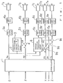
- FIG. 1 shows in block form a numerical control system for controlling a CNC laser beam machining apparatus according to the present invention.
- the numerical control system includes an interpolator 1 that is supplied with commands with respect to paths (X, Y, Z) of a control point to be machined, and an attitude ( ⁇ , ⁇ ) of a nozzle.
- the interpolator 1 effects simultaneous interpolation for the five axes.
- the X-, Y-, and Z-axes should be interpolated taking into account the movement of the ⁇ - and ⁇ -axes.
- Such an interpolation would require vector calculations and result in an enormous period of calculation, and hence would not be able to effect laser beam machining at practical speed.
- the interpolator 1 interpolates the X-, Y-, and Z-axes while ignoring the movement of the ⁇ - and ⁇ -axes. Therefore, the interpolation of the X-, Y-, and Z-axes is the same as the interpolation in ordinary numerical control systems, and can be calculated at high speed.
- the numerical control system also includes a corotation compensating means 2 for calculating a corotation corrective for the ⁇ -axis from an interpolation output P ⁇ for the ⁇ -axis from the interpolator 1. Details of such calculation will be described later on.
- the corotation compensating means 2 includes a register 3 for storing a remainder that is produced when the corotation corrective is calculated.
- the corotation corrective, denoted by ⁇ , from the corotation compensating means 2 is added to an interpolation output P ⁇ for the ⁇ -axis from the interpolator 1 by an adder 4.
- the interpolation output P ⁇ , and the interpolation output P ⁇ with the corotation corrective ⁇ added thereto, are supplied to axis control circuits 5a, 5b, respectively.
- Output signals from the axis control circuits 5a, 5b are amplified by respective servoamplifiers 6a, 6b, which energize respective servomotors 7a, 7b to control the rotation of components about the ⁇ - and ⁇ -axes.
- the numerical control system further includes a nozzle position correcting means 8 for calculating correctives ⁇ X, ⁇ Y, ⁇ Z to be given to the X-, Y-, and Z-axes upon movement of the ⁇ - and ⁇ -axes.
- the calculation of the correctives ⁇ X, ⁇ Y, ⁇ Z can be effected at higher speed than would be if simultaneous interpolation were carried out for the five axes.
- the correctives ⁇ X, ⁇ Y, ⁇ Z are added to interpolation outputs PX, PY, PZ for the X-, Y-, and Z-axes from the interpolator 1 by respective address 9a, 9b, 9c, which supply sum output signals to respective axis control circuits 5c, 5d, 5e.
- Output signals from the axis control circuits 5c, 5d, 5e are amplified by respective servoamplifiers 6c, 6d, 6e which energize respective servomotors 7c, 7d, 7e to control the rotation of components about the X-, Y-, and Z-axes. In this manner, the nozzle is controlled so as not to change in its position regardless of the rotation about the ⁇ - and ⁇ -axes.
- the interpolator 1, the corotation compensating means 2, the nozzle position correcting means 8, the adder 4, and the other circuits are controlled by a microprocessor in the numerical control system.
- the nozzle position correcting means 8 is controlled by a dedicated microprocessor to make it possible to effect three-dimensional laser beam machining at high speed.
- the nozzle position correcting means 8 is necessary for use with an offset type nozzle head mechanism, but is not required by a zero-offset type nozzle head mechanism because the position of the tip end of the nozzle remains unchanged upon rotation about the ⁇ - and ⁇ -axes.
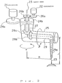
- FIG. 2 shows an offset type nozzle head mechanism according to an embodiment of the present invention.
- a servomotor 21 actuates components to rotate about an ⁇ -axis
- a servomotor 22 actuates components to rotate about a ⁇ -axis.
- a laser beam 23 is guided to the tip end of a nozzle 29a by reflecting mirrors (not shown), and applied to a workpiece.
- the ⁇ -axis is a rotational axis with respect to a Z-axis.
- An arm 25 is rotatable about the ⁇ -axis by the servomotor 21 which transmits its rotation through gears 24a, 24b to the arm 25.
- the correctives in the nozzle position correcting means 8 can be determined by the following equations:
- the trigonometric functions, etc. can be determined at higher speed if a coprocessor or the like is employed.
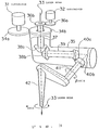
- FIG. 3 shows a zero-offset type nozzle head mechanism according to an embodiment of the present invention.
- a servomotor 31 actuates components to rotate about an ⁇ -axis
- a servomotor 32 actuates components to rotate about a ⁇ -axis.
- a laser beam 33 is guided to the tip end of a nozzle 42 by reflecting mirrors (not shown), and applied to a workpiece.
- the ⁇ -axis is a rotational axis with respect to a Z-axis.
- An arm 35 is rotatable about the ⁇ -axis by the servomotor 31 which transmits its rotation through gears 34a, 34b to the arm 35.
- the arm 35 rotates about the ⁇ -axis, and hence the horizontal shaft 39 also rotates about the ⁇ -axis.
- the meshing bevel gears 38a, 38b also rotate to cause the ⁇ -axis to rotate with the rotation about the ⁇ -axis.
- the corotation of the ⁇ -axis can also be compensated for by the corotation compensating means 2 as with the offset type nozzle head mechanism described above. More specifically, with the gear ratio of the bevel gears 38a, 38b being a : b, the corotation corrective ⁇ is determined according to the above equation, and added to the interpolation output P ⁇ for the ⁇ -axis.
- the gear ratio a : b may not necessarily be an integer.
- a corotation of the ⁇ -axis caused by a rotation about the ⁇ -axis can be compensated for irrespective of the gear ratio of the gears by which the horizontal and vertical shafts of the ⁇ -axis are coupled to each other.
- the corotation compensating means is provided to compensate for a corotation caused by a rotation about the ⁇ -axis irrespective of the gear ratio of the gears by which the horizontal and vertical shafts of the ⁇ -axis are coupled to each other.
- the gear ratio of the nozzle head mechanism can freely be selected.
Landscapes
- Engineering & Computer Science (AREA)
- Physics & Mathematics (AREA)
- Optics & Photonics (AREA)
- Theoretical Computer Science (AREA)
- Mechanical Engineering (AREA)
- Computing Systems (AREA)
- Plasma & Fusion (AREA)
- Human Computer Interaction (AREA)
- Manufacturing & Machinery (AREA)
- General Physics & Mathematics (AREA)
- Automation & Control Theory (AREA)
- Laser Beam Processing (AREA)
- Manipulator (AREA)
- Numerical Control (AREA)
Applications Claiming Priority (2)
| Application Number | Priority Date | Filing Date | Title |
|---|---|---|---|
| JP2081693A JPH03281083A (ja) | 1990-03-29 | 1990-03-29 | Cncレーザ加工機の姿勢制御方式 |
| JP81693/90 | 1990-03-29 |
Publications (2)
| Publication Number | Publication Date |
|---|---|
| EP0480046A1 true EP0480046A1 (en) | 1992-04-15 |
| EP0480046A4 EP0480046A4 (enExample) | 1994-02-23 |
Family
ID=13753446
Family Applications (1)
| Application Number | Title | Priority Date | Filing Date |
|---|---|---|---|
| EP91906284A Ceased EP0480046A1 (en) | 1990-03-29 | 1991-03-13 | Method of controlling attitude of cnc laser working machine |
Country Status (4)
| Country | Link |
|---|---|
| US (1) | US5216222A (enExample) |
| EP (1) | EP0480046A1 (enExample) |
| JP (1) | JPH03281083A (enExample) |
| WO (1) | WO1991014531A1 (enExample) |
Cited By (2)
| Publication number | Priority date | Publication date | Assignee | Title |
|---|---|---|---|---|
| WO2003032098A3 (de) * | 2001-10-04 | 2004-08-19 | Heidenhain Gmbh Dr Johannes | Verfahren zur bahnsteuerung |
| DE112021002634B4 (de) * | 2020-07-31 | 2025-05-15 | Fanuc Corporation | Steuervorrichtung und Robotersystem |
Families Citing this family (13)
| Publication number | Priority date | Publication date | Assignee | Title |
|---|---|---|---|---|
| DE9310029U1 (de) * | 1993-07-06 | 1993-12-02 | Wissner, Rolf, Dipl.-Ing., 37079 Göttingen | Fräs- oder Lasermaschine zur Herausarbeitung eines Werkstücks aus insbesondere plattenförmigem Material |
| JPH07112287A (ja) * | 1993-10-15 | 1995-05-02 | Fanuc Ltd | Ncレーザ装置 |
| JP3476288B2 (ja) * | 1995-08-31 | 2003-12-10 | ファナック株式会社 | Yagカッティングツールを用いた立体加工装置 |
| US6325697B1 (en) | 1999-11-24 | 2001-12-04 | Glassline Corporation | CNC machine tools |
| US6479790B1 (en) * | 2000-01-31 | 2002-11-12 | General Electric Company | Dual laser shock peening |
| JP3383832B2 (ja) | 2000-12-25 | 2003-03-10 | 川崎重工業株式会社 | レーザ照射装置 |
| US7538296B2 (en) * | 2005-09-06 | 2009-05-26 | Pratt & Whitney Canada Corp. | High speed laser drilling machine and method |
| US9242309B2 (en) * | 2012-03-01 | 2016-01-26 | Foro Energy Inc. | Total internal reflection laser tools and methods |
| DE102010032958A1 (de) * | 2010-07-30 | 2012-02-02 | Messer Cutting & Welding Gmbh | Verfahren und Vorrichtung zum thermischen Bearbeiten eines Werkstücks mittels Laserstrahl |
| CN102528279A (zh) * | 2012-02-02 | 2012-07-04 | 江苏扬力数控机床有限公司 | 一种三维激光切割机 |
| GB2541369B (en) | 2015-07-22 | 2021-03-31 | Cmr Surgical Ltd | Drive mechanisms for robot arms |
| JP6330017B1 (ja) * | 2016-12-20 | 2018-05-23 | 株式会社アマダホールディングス | パンチ・レーザ複合加工機によるワークの加工方法及びパンチ・レーザ複合加工機 |
| JP2020506815A (ja) * | 2017-02-08 | 2020-03-05 | ユニバーシティ オブ プレトリア | ロボット |
Family Cites Families (9)
| Publication number | Priority date | Publication date | Assignee | Title |
|---|---|---|---|---|
| JPS5962909A (ja) * | 1982-10-01 | 1984-04-10 | Fanuc Ltd | 加減速装置 |
| US4621333A (en) * | 1983-08-31 | 1986-11-04 | Mitsubishi Denki Kabushiki Kaisha | Method and apparatus for controlling a robot to perform weaving-like motion |
| US4689756A (en) * | 1984-06-29 | 1987-08-25 | Shin Meiwa Industry Co., Ltd. | Robot interpolation control method |
| JPS6118009A (ja) * | 1984-07-04 | 1986-01-25 | Fanuc Ltd | 加減速制御方式 |
| DE3445981A1 (de) * | 1984-12-17 | 1986-06-19 | Messer Griesheim Gmbh, 6000 Frankfurt | Einrichtung zum bearbeiten von werkstuecken mit einem aus einem laserkopf austretenden laserstrahl |
| JPH01122683A (ja) * | 1987-11-05 | 1989-05-15 | Mitsubishi Electric Corp | 3次元レーザ加工機 |
| JPH0714559B2 (ja) * | 1987-12-18 | 1995-02-22 | ファナック株式会社 | Cncレーザ加工機の姿勢制御装置 |
| JP2807461B2 (ja) * | 1988-01-08 | 1998-10-08 | ファナック 株式会社 | 三次元形状加工レーザ装置 |
| JPH01224194A (ja) * | 1988-03-03 | 1989-09-07 | Fanuc Ltd | Cncレーザ加工機の姿勢制御方式 |
-
1990
- 1990-03-29 JP JP2081693A patent/JPH03281083A/ja active Pending
-
1991
- 1991-03-13 WO PCT/JP1991/000357 patent/WO1991014531A1/ja not_active Ceased
- 1991-03-13 US US07/773,594 patent/US5216222A/en not_active Expired - Lifetime
- 1991-03-13 EP EP91906284A patent/EP0480046A1/en not_active Ceased
Cited By (3)
| Publication number | Priority date | Publication date | Assignee | Title |
|---|---|---|---|---|
| WO2003032098A3 (de) * | 2001-10-04 | 2004-08-19 | Heidenhain Gmbh Dr Johannes | Verfahren zur bahnsteuerung |
| US7012395B2 (en) | 2001-10-04 | 2006-03-14 | Dr. Johannes Heidenhain Gmbh | Method for continuous-path control |
| DE112021002634B4 (de) * | 2020-07-31 | 2025-05-15 | Fanuc Corporation | Steuervorrichtung und Robotersystem |
Also Published As
| Publication number | Publication date |
|---|---|
| JPH03281083A (ja) | 1991-12-11 |
| US5216222A (en) | 1993-06-01 |
| WO1991014531A1 (fr) | 1991-10-03 |
| EP0480046A4 (enExample) | 1994-02-23 |
Similar Documents
| Publication | Publication Date | Title |
|---|---|---|
| EP0480046A1 (en) | Method of controlling attitude of cnc laser working machine | |
| EP0158447B1 (en) | System for controlling a robot in association with a rotary table | |
| US20030120376A1 (en) | Numerical controller | |
| US5563484A (en) | Three-dimensional cutter compensation system | |
| US5384523A (en) | Three-dimensional laser coordinate transformation system | |
| EP0510204A1 (en) | Method of evaluating operating accuracy in numerically controlled machine | |
| JPS5775309A (en) | Numerical control system | |
| JP2005071016A (ja) | 数値制御装置 | |
| EP0485615B1 (en) | Method of moving nozzle of laser beam machine | |
| JPH0457008B2 (enExample) | ||
| EP0484539B1 (en) | Cylinder interpolation system | |
| EP0520075B1 (en) | Non-contact digitizing method | |
| JPS62163109A (ja) | 数値制御装置 | |
| US5341079A (en) | Tracking control system | |
| JP2686293B2 (ja) | 3次元レーザ加工方法 | |
| US5550330A (en) | Digitizing control apparatus | |
| JPH05216516A (ja) | レーザ加工機 | |
| JP3267734B2 (ja) | Cncレーザ加工機 | |
| JPH01224194A (ja) | Cncレーザ加工機の姿勢制御方式 | |
| EP0563407B1 (en) | Digitizing controller | |
| JPH0454604A (ja) | 3次元工具経補正機能を有する数値制御装置 | |
| JP2806955B2 (ja) | 3次元工具補正方法 | |
| JPH0474205A (ja) | 数値制御装置 | |
| JPH02274457A (ja) | ならい制御装置 | |
| JPH02151387A (ja) | 3次元レーザのノズル制御方式 |
Legal Events
| Date | Code | Title | Description |
|---|---|---|---|
| PUAI | Public reference made under article 153(3) epc to a published international application that has entered the european phase |
Free format text: ORIGINAL CODE: 0009012 |
|
| 17P | Request for examination filed |
Effective date: 19911219 |
|
| AK | Designated contracting states |
Kind code of ref document: A1 Designated state(s): DE FR GB IT |
|
| RBV | Designated contracting states (corrected) |
Designated state(s): DE IT |
|
| A4 | Supplementary search report drawn up and despatched |
Effective date: 19940103 |
|
| AK | Designated contracting states |
Kind code of ref document: A4 Designated state(s): DE FR GB IT |
|
| GRAG | Despatch of communication of intention to grant |
Free format text: ORIGINAL CODE: EPIDOS AGRA |
|
| 17Q | First examination report despatched |
Effective date: 19951206 |
|
| STAA | Information on the status of an ep patent application or granted ep patent |
Free format text: STATUS: THE APPLICATION HAS BEEN REFUSED |
|
| 18R | Application refused |
Effective date: 19960525 |