EP0478701B1 - Vehicule chenille utilise pour les travaux - Google Patents
Vehicule chenille utilise pour les travaux Download PDFInfo
- Publication number
- EP0478701B1 EP0478701B1 EP90912043A EP90912043A EP0478701B1 EP 0478701 B1 EP0478701 B1 EP 0478701B1 EP 90912043 A EP90912043 A EP 90912043A EP 90912043 A EP90912043 A EP 90912043A EP 0478701 B1 EP0478701 B1 EP 0478701B1
- Authority
- EP
- European Patent Office
- Prior art keywords
- assemblies
- work vehicle
- roller frame
- support beam
- assembly
- Prior art date
- Legal status (The legal status is an assumption and is not a legal conclusion. Google has not performed a legal analysis and makes no representation as to the accuracy of the status listed.)
- Expired - Lifetime
Links
- 230000000712 assembly Effects 0.000 claims abstract description 81
- 238000000429 assembly Methods 0.000 claims abstract description 81
- 239000013536 elastomeric material Substances 0.000 claims description 6
- 239000002689 soil Substances 0.000 description 6
- 238000005056 compaction Methods 0.000 description 4
- 239000000463 material Substances 0.000 description 3
- 239000002184 metal Substances 0.000 description 3
- 239000000725 suspension Substances 0.000 description 2
- 230000005540 biological transmission Effects 0.000 description 1
- 238000005266 casting Methods 0.000 description 1
- 238000010276 construction Methods 0.000 description 1
- 239000012530 fluid Substances 0.000 description 1
- 238000012423 maintenance Methods 0.000 description 1
- 230000013011 mating Effects 0.000 description 1
- 230000007246 mechanism Effects 0.000 description 1
- 238000012856 packing Methods 0.000 description 1
- 230000003014 reinforcing effect Effects 0.000 description 1
Images


Classifications
-
- B—PERFORMING OPERATIONS; TRANSPORTING
- B62—LAND VEHICLES FOR TRAVELLING OTHERWISE THAN ON RAILS
- B62D—MOTOR VEHICLES; TRAILERS
- B62D55/00—Endless track vehicles
- B62D55/08—Endless track units; Parts thereof
-
- Y—GENERAL TAGGING OF NEW TECHNOLOGICAL DEVELOPMENTS; GENERAL TAGGING OF CROSS-SECTIONAL TECHNOLOGIES SPANNING OVER SEVERAL SECTIONS OF THE IPC; TECHNICAL SUBJECTS COVERED BY FORMER USPC CROSS-REFERENCE ART COLLECTIONS [XRACs] AND DIGESTS
- Y10—TECHNICAL SUBJECTS COVERED BY FORMER USPC
- Y10S—TECHNICAL SUBJECTS COVERED BY FORMER USPC CROSS-REFERENCE ART COLLECTIONS [XRACs] AND DIGESTS
- Y10S180/00—Motor vehicles
- Y10S180/906—Adjustable axles
Definitions
- This invention relates generally to track laying work vehicles and more particularly to roller frame assemblies for such vehicles which support the vehicle, a plurality of belt guiding rollers, and the idler wheels.
- Construction, earthmoving, and agricultural type work vehicles are often equipped with endless self-laying track chain assemblies for support and propulsion of the vehicle.
- Such prior art track type vehicles, utilizing metal track chain assemblies are generally low speed vehicles and work in environments not requiring relatively high ground clearance beneath the vehicle.
- work vehicles having endless, inextensible elastomeric track belts have been employed to perform work tasks previously accomplished by metal track equipped vehicles.
- the elastomeric track belt vehicles have many advantages over metal track vehicles and also over wheel type vehicles. Some of these advantages include less weight and maintenance, lower soil compaction, and the ability to travel on improved roadways.
- each of the endless elastomeric belts is driven by a pair of elevated drive wheels and is guided and supported by a pair of large diameter idler wheels and a plurality of smaller diameter roller assemblies.
- the idler wheels and roller assemblies are supported and suspended by a plurality of links, levers, and fluid cylinders. This large number of components in the undercarriage and suspension adds complexity, weight, and cost to the vehicle.
- U.S.-A-4,836,318 Another type of belted vehicle having a track roller frame assembly is disclosed in U.S.-A-4,836,318.
- This patent discloses a vehicle having a track roller frame which is connected to the front of the vehicle by a pivot joint, and is connected to the rear of the vehicle by a collar which extends between the two drive wheels.
- the track roller frame also has an inside support device which connects the roller frame to the vehicle on the inside of the drive wheels.
- Prior art vehicles utilized in agricultural operations are generally equipped with a plurality of wheels which support and propel the vehicle.
- the wheels provide high ground clearance for crop cultivation and are generally adjustable to accommodate various row crop spacings.
- Wheel type vehicles tend to cause undesirable soil compaction and their use is somewhat limited in wet soil conditions.
- Track type vehicles provide greater traction in wet soil conditions and less soil compaction, but are limited in their ground clearance and the tracks cannot be adjusted to accommodate different row crop spacings.
- US-A-4817746 discloses a track laying work vehicle, comprising: a main frame assembly having first and second opposed sides and a longitudinal centerline; an engine; first and second roller frame assemblies, each having first and second end portions, and each positioned substantially parallel to the longitudinal centerline of the vehicle; first and second drive axles, each rotatably connected to said engine; first and second drive wheels, each rotatably connected to a respective drive axle; first and second idler assemblies, each rotatably connected to a respective roller frame assembly; and first and second endless elastomeric track belts, each belt having an inner friction drive surfaces having a plurality of guide blocks, each belt encircling a respective roller frame assembly, idler assembly, and drive wheel; and according to the present invention, such a vehicle is characterised by a roller frame support beam having first and second end portions and a middle portion, said middle portion extending transverse to and beneath said main frame assembly and being connected to said main frame assembly; first and second roller frame extensions, each having first and second end portions, each first end
- the subject invention provides a tracked vehicle having track assemblies which are laterally adjustable to a plurality of gage widths and which can be designed to have a high ground clearance.
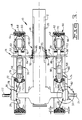
- a track laying work vehicle 10 has a main frame assembly 12, a power generating means such as an engine 14, and an undercarriage assembly 16.
- the main frame assembly 12 includes first and second opposed spaced apart parallel side portions 18, 20.
- First and second drive axles 22,24 are rotatably connected to and powered by the engine 14 through a transmission and other standard control mechanisms, which are well known in the art.
- First and second drive wheels 26,28 are rotatably connected respectively to the first and second drive axles 22,24 through first and second friction clamp assemblies 30,32.
- the clamp assemblies 30,32 are releasably connected to a respective drive axle 22,24 and the drive wheels 26,28 are connected to a respective clamp assembly 30,32.
- the vehicle 10 is supported and propelled by the undercarriage assembly 16, which includes first and second auxiliary roller frame assemblies 36,38 first and second idler wheel assemblies 40,42, a plurality of guide rollers 44, a rigid roller frame support beam 46, and first and second endless track assemblies 48,50.
- Each idler wheel assembly includes first and second spaced apart idler wheels 51,53.
- Each of the track assemblies 48,50 encircles a respective one of the drive wheels 26,28, the roller frame assemblies 36,38, the guide rollers 44, and the idler wheel assemblies 40,42.
- the guide rollers 44 are rotatably connected to the roller frame assemblies 36,38.
- Each of the roller frame assemblies 36,38 has first and second end portions 52,54 and 56,58 respectively, and each roller frame assembly 36,38 is substantially parallel to each other and spaced from a respective main frame side portion 18,20.
- Each of the idler wheel assemblies 40,42 is rotatably connected to a respective first end portion 52,56 of the roller frame assemblies 36,38.
- the track assemblies 48,50 include endless elastomeric belts 60,62.
- Each belt 60,62 has a respective inner friction drive surface 64,66 and a plurality of guide blocks 68,70 bonded to, or integrally formed with the inner drive surfaces 64,66.
- the undercarriage assembly 16 further includes first and second roller frame extensions, or arm members, 72,74 with each being connected between a respective clamp assembly 30,32 and a roller frame assembly 36,38.
- Each roller frame extension 72,74 has first and second end portions 76,78 and 80,82 respectively, with the first end portions 76,80 being connected to a respective second end portion 54,58 of the roller frame assemblies 36,38, and the second end portions 78,82 being connected to a respective drive axle 22,24 through the first and second clamp assemblies 30,32.
- These connections are the only connections between the second end portions of the roller frame assemblies 36,38 and the vehicle 10.
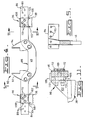
- the support beam 46 has first and second end portions 84,86 and a middle portion 88. Each of the first and second end portions 84,86 has a plurality of first mounting holes 89 which are arranged in a preselected pattern.
- the middle portion 88 extends transverse to and beneath the main frame assembly 12 and is releasably connected to the first and second side portions 18,20 by a first means 90, including first and second hanger assemblies 92,94.
- the hanger assemblies 92,94 are removably connected to the main frame side portions 18,20 by a plurality of threaded fasteners 95.
- Each of the first and second end portions 84,86 of the support beam 46 are releasably connected by a second connecting means 96 to a respective first end portion 52,56 of the roller frame assemblies 36,38.
- the second connecting means 96 includes first and second bracket assemblies 98,100 which provide a plurality of connected positions between each end portion 84,86 of the support beam 46 and the respective roller frame assembly 36,38.
- the roller frame assemblies 36,38 are moveable along the respective support beam end portions 84,86 and are connectable at the different positions to provide a variable gage of the track assemblies 48,50.
- each of the bracket assemblies 98,100 includes first and second parallel plates 102, 104, joined together by a third plate 106.
- a fourth plate 108 is joined to the top surface of the third plate 106.
- the third plate 106 has a plurality of second mounting holes 110 arranged in a second preselected pattern.
- Each plate 106 is removably connected to the support beam 46 by a plurality of threaded fasteners 112 which penetrate respective holes 89 in the support beam 46 and holes 110 in the plate 106.
- the bracket assemblies 98,100, and the attached roller frame assemblies 38,40 can be moved along the support beam 46 and connected to the support beam at a plurality of positions, wherever the second preselected pattern of holes in the plates 106 align with one of the first preselected patterns of holes in the support beam 46.
- the support beam 46 has been illustrated with a plurality of connecting and adjusting holes 89, these holes 89 could be replaced with a plurality of elongated slots. Such slots would provide even greater lateral adjusting capabilities.
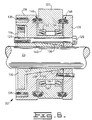
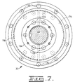
- the clamp assembly 32 includes first and second wedge members 114,116, a hub member 118, a bearing cage 120, first and second bearing assemblies 122,124, a retainer plate 126, and means for connecting the various clamp members together, including a plurality of threaded fasteners 128.
- the threaded fasteners are adapted to mate with a plurality of threaded holes 129 in the wedge members 114,116.
- the hub member 118 has an internal cavity 130 having a tapered wall portion 132, and a journal portion 134 adapted to receive the inner races of the bearing assemblies 122,124.
- the hub member also has a plurality of threaded holes 135.
- the wedge members 114,116 have outer taper wall portions 136,138 respectively, which are adapted to mate with the tapered wall portion 132 of the hub member 118.
- the wedge members 114,116 also have inner wall surfaces 140,142 respectively, which are adapted to mate with and clamp onto the drive axle 24.
- the bearing cage 120 has a stepped internal bore 144 which is adapted to receive the outer races of the bearing assemblies 122,124.
- the bearing assemblies 122,124 are therefore positioned between the bearing cage bore 144 and the hub member journal portion 134 and provide relative rotation between the hub member 120 and the other members of the clamp assembly 32.
- First and second seal assemblies 146,148 are positioned between the hub member 118 and the bearing cage 120 and between the retainer plate 126 and the bearing cage 120 respectively.
- Each of the drive wheels 26,28 is rotatably connected to a respective drive axle through a respective clamp assembly 30,32.
- Each of the drive wheels 26,28 is connected to the hub member 118 by a plurality of threaded fasteners 150, which mate with the thread holes 135.
- each of the drive wheels 26,28 includes a disc portion 152 having a mounting surface 154, and a rim portion 156 having an inwardly directed recess 158.
- the rim portion 156 has a layer of elastomeric material 160 bonded thereto which, with the recess 158, provides a deep recess 162 which has a preselected depth dimension "D".
- Each of the guide blocks 68,70 has a preselected height dimension "d” and the deep recess 160 is adapted to receive the guide blocks 68,70.
- the preselected dimensions of the recess 160 and the guide blocks 68,70 provide that depth dimension "D" is greater than height dimension "d”.
- the drive wheels 26,28 have a diameter which is larger than the diameter of the idler wheels 51,53.
- each of the drive wheels 26,28 is connected to a respective drive axle 22,24 at a position between the main frame and a respective roller frame extension 72,74.
- Drive wheel 164 includes a disc portion 168 having a mounting surface 170, and a rim portion 172.
- the rim portion 172 has first and second spaced rim surfaces 174,176 which frictionally contact the elastomeric belts 60,62.
- a deep recess 178 is formed between the rim surfaces 174,176 to accommodate the guide blocks 68,70.
- the rim portion 172, including rim surfaces 174,176 are entirely metallic with the rim portion 172 being press formed or formed by casting. Spaced reinforcing ribs 180 can be provided to strengthen the rim surfaces 174,176.
- the disc portion 168 and the rim portion 172 are generally formed as individual members and are joined in any suitable manner at a joint 182. If desirable, spaced openings 184 can be provided in the rim surfaces 174,176 to create enhanced traction between the rim surfaces 174,176 and the inner drive surfaces 64,66 of the belts 60,62. These openings 184 will also allow foreign material to be expelled from the rim surfaces 174,176 and the drive surfaces 64,66.
- Drive wheel 166 is similar to the drive wheels 26,28 and includes a disc portion 186 having a mounting surface 188, and a rim portion 190 having first and second rim surfaces 192,194.
- Each of the rim surfaces 192,194 has a layer of elastomeric material 196 bonded,or formed,thereon.
- a moderately deep recess 198 is formed between the rim surfaces 192,194 and, together with the layer of elastomeric material 196 forms a recess to accommodate the guide blocks 68,70.
- a small layer of elastomeric material 200 can be provided at the base of the recess 198 to reduce packing of foreign material in the recess 198.
- the elastomeric material 196 is provided with spaced lugs or grousers 202 which enhance friction drive characteristics between the belts 60,62 and the drive wheel 166 by allowing foreign material to escape.
- the subject track laying vehicle 10 is particularly useful as an agricultural type work vehicle. It is advantageous that such a vehicle 10 have good traction, low ground pressure, low soil compaction, relatively high ground clearance, and have variable gage capabilities. The variable gage is especially useful for operating the vehicle in agricultural fields having different row crop spacings.
- the vehicle 10 is supported and propelled by an undercarriage assembly 16 which includes first and second roller frame assemblies 36,38, first and second idler wheel assemblies 40,42, first and second drive wheels 26,28, and first and second endless elastomeric track assemblies 48,50.
- the idler wheel assemblies 40,42 are rotatably connected to the first end portions 52,56 of the roller frame assemblies 36,38 and the drive wheels 26,28 are rotatably connected to and powered by the drive axles 22,24. These connections include first and second friction clamp assemblies 30,32 to which the drive wheel 26,28 are connected respectively.
- the clamp assemblies 30,32 include tapered wedge members 114,116 which are frictionally clamped onto the drive axles 22,24 and to the tapered wall portions 132 of the hub members 118.
- the wedge members are forced into contact with the axles 22,24 and the tapered wall portions 132 by a plurality of threaded fasteners 128 which extend through the retainer plate 126, the hub member 118, and into the threaded holes 129 in the wedge members 114,116.
- the bearing cage 120 is connected to second end portions 78,82 of the first and second arm members 72,74, and the bearing assemblies 122,124 provide relative rotation between the bearing cage 120 and the other members of the clamp assemblies 30,32.
- the threaded fasteners 112 are removed from the support beam 46 and the bracket assemblies 98,100. With the threaded fasteners 112 removed, the brackets 98,100, which are connected to the roller frame assemblies 36,38, can be moved to another lateral position on the support beam 46 until the holes in the plate 106 align with the mating holes 89 in the support beam 46. At this same time, the threaded fasteners 128 are threaded into the threaded holes 129 in the wedge members 114,116 to again frictionally clamp the wedge members 114,116 against the drive axles 22,24 and against the tapered wall portions 132.
- the threaded fasteners 112 are then reconnected to the support beam 46 and the bracket assemblies 98,100. While the roller frame assemblies 36,38 are being adjusted, the vehicle must be supported in some manner to relieve the weight on the roller frame assembly being adjusted. This can be accomplished in several ways, including a lifting device supporting the rear axle and the front support beam 46.
- roller frame assemblies 36,38 Additional adjustability, to increase the gage width of the roller frame assemblies 36,38, is possible by reversing the similar roller frame assemblies side to side. This would position the arm members 72,74 and the clamp assemblies 30,32 to the inside and the drive wheels 26,28 to the outside.
Landscapes
- Engineering & Computer Science (AREA)
- Chemical & Material Sciences (AREA)
- Combustion & Propulsion (AREA)
- Transportation (AREA)
- Mechanical Engineering (AREA)
- Road Paving Machines (AREA)
- Platform Screen Doors And Railroad Systems (AREA)
- Guiding Agricultural Machines (AREA)
Abstract
Claims (19)
- Véhicule de travaux à chenille (10) comprenant un châssis principal (12) ayant des premier et second côtés opposés (18, 20) et un axe longitudinal ; un moteur (14) ; des premier et second châssis de roulement (36, 38) dont chacun comporte des première et seconde parties d'extrémité (52, 54, 56, 58) et est positionné de façon sensiblement parallèle à l'axe longitudinal du véhicule ; des premier et second ans d'entraînement (22, 24) dont chacun est relié à rotation au moteur (14) ; des première et seconde roues d'entraînement (26, 28), chacune étant reliée à rotation à un axe d'entraînement respectif (22, 24) ; des premier et second montages fous (40, 42) dont chacun est relié à rotation à un châssis de roulement respectif (36, 38) ; et des première et seconde bandes sans fin de chenille en élastomère (60, 62), chaque bande ayant une surface d'entraînement interne à friction (64, 66) comportant une pluralité de blocs de guidage (68, 70), chaque bande entourant un châssis de roulement (36, 38), un montage fou (40, 42) et une roue d'entraînement (26, 28) respectifs ; caractérisé par une poutre support de châssis de roulement (46) ayant des première et seconde parties d'extrémité (84, 86) et une partie médiane (88), la partie médiane (88) s'étendant transversalement et sous le châssis principal (12) et étant liée au châssis principal (12) ; des première et seconde extensions du châssis de roulement (72, 74) ayant chacune des première et seconde parties d'extrémité (76, 78, 80, 82), chaque première partie d'extrémité (76, 80) étant reliée à une seconde partie d'extrémité respective (54, 58) des premier et second châssis de roulement (36, 38) et chaque seconde partie d'extrémité (78, 82) étant reliée à un premier et un second axe respectif d'entraînement (22, 24) ; des premier et second ensembles de blocage (30, 32) dont chacun est relié de façon démontable à un axe d'entraînement respectif (22, 24) ; et chacun des premier et second châssis de roulement (36, 38) pouvant être relié de façon amovible à une première et une seconde partie d'extrémité respective (84, 86) de la poutre support de châssis de roulement (46) et étant mobile le long de celle-ci.
- Véhicule de travaux (10) selon la revendication 1, dans lequel chacun des premier et second rouleaux d'entraînement (26, 28) est relié à un montage de blocage respectif (30, 32).
- Véhicule de travaux (10) selon la revendication 1 ou 2, dans lequel chacune des secondes parties d'extrémité (78, 82) des extensions du châssis de roulement (72, 74) est liée à un montage de blocage respectif (30, 32), ces liaisons constituant les seules liaisons entre les secondes parties d'extrémité (54, 58) des châssis de roulement (36, 38) et le véhicule (10).
- Véhicule de travaux (10) selon l'une quelconque des revendications précédentes, dans lequel chacun des montages de blocage (30, 32) comprend un montage à palier (122, 124).
- Véhicule de travaux (10) selon l'une quelconque des revendications précédentes, dans lequel chacun des premier et second montages de blocage (30, 32) est mobile latéralement par rapport à un axe respectif (22, 24).
- Véhicule de travaux (10) selon l'une quelconque des revendications précédentes, dans lequel chacune des roues d'entraînement (26, 28) est reliée à un axe d'entraînement respectif (22, 24) à une position située entre le châssis principal (12) et une extension respective du châssis de roulement (72, 74).
- Véhicule de travaux (10) selon l'une quelconque des revendications précédentes, dans lequel les première et seconde parties d'extrémité (84, 86) de la poutre support de châssis de roulement (46) ont une pluralité de premiers trous (89), les trous (89) étant disposés selon une pluralité de premiers motifs prédéterminés.
- Véhicule de travaux (10) selon la revendication 7, dans lequel les liaisons entre le châssis support (46) et des premier et second châssis de roulement (36, 38) comprennent des première et seconde brides (98, 100), chacune des brides (98, 100) comportant une pluralité de seconds trous (110) disposés selon un second motif prédéterminé, les brides (98, 100) pouvant être reliées de façon démontable à la poutre support (46) par une pluralité de moyens de liaison à vis (112), les moyens de liaison à vis (112) étant adaptés à pénétrer dans des trous respectifs (89, 110) du châssis support (46) et des brides (98, 100).
- Véhicule de travaux (10) selon l'une quelconque des revendications précédentes comprenant une pluralité de montages à rouleaux de guidage de bande (44).
- Véhicule de travaux (10) selon l'une quelconque des revendications précédentes dans lequel chacun des premier et second montages de blocage (30, 32) comprend des premier et second éléments de coin (114, 116), un élément de moyeu (118) comportant une cavité interne (130) et une partie de palier (134) et adapté à recevoir les éléments de coin (114, 116) dans la cavité interne (130), un support de roulement (120) ayant un alésage interne (144), des première et seconde structures de roulement (122, 124) disposées entre l'alésage de support de roulement (144) et la partie de palier (134) de l'élément de moyeu, une plaque de maintien (126), et des moyens (135) pour relier les uns aux autres l'élément de moyeu (118), le support de roulement (120), les coins (114, 116), et la plaque de maintien (126).
- Véhicule de travaux (10) selon la revendication 10, dans lequel chacune des première et seconde roues d'entraînement (26, 28) est reliée à un élément de moyeu respectif (118) des premier et second ensembles de blocage (30, 32).
- Véhicule de travaux (10) selon l'une quelconque des revendications précédentes, dans lequel chacun des premier et second montages fous (40, 42) comprend des première et seconde roues folles espacées (51, 53).
- Véhicule de travaux (10) selon la revendication 12, dans lequel les roues d'entraînement (26, 28) ont un diamètre supérieur au diamètre des roues folles (51, 53).
- Véhicule de travaux (10) selon l'une quelconque des revendications précédentes, comprenant des premier et second ensembles de suspension (92, 94) dont chacun est relié à un premier et un second côté respectif (18, 20) du châssis principal (12), et à la partie médiane de la poutre support (46).
- Véhicule de travaux (10) selon la revendication 14, dans lequel les ensembles de suspension (92, 94) sont reliés de façon démontable aux côtés du châssis principal (18, 20) par une pluralité de moyens de liaison filetés (95).
- Véhicule de travaux (10) selon l'une quelconque des revendications précédentes dans lequel chacune des roues d'entraînement (26, 28) comprend une partie de disque (152) ayant une surface de montage (154) et une partie de rebord (156) comportant un évidement (158) dirigé vers l'intérieur, l'évidement (158) étant adapté à recevoir les blocs de guidage (68, 70) de la bande de chenille (60, 62).
- Véhicule de travaux (10) selon la revendication 16, dans lequel les blocs de guidage (68, 70) ont une hauteur "d" et dans lequel l'évidement (158) a une profondeur "D" supérieure à la hauteur "d".
- Véhicule de travaux (10) selon la revendication 16 ou 17, dans lequel la partie de rebord (156) comprend une couche de matériau élastomère (160) liée à la partie de rebord (156).
- Véhicule de travaux (10) selon l'une quelconque des revendications précédentes comprenant en outre une pluralité de rouleaux de guidage (44) reliés à rotation à chaque châssis de roulement (36, 38).
Applications Claiming Priority (3)
| Application Number | Priority Date | Filing Date | Title |
|---|---|---|---|
| US07/513,746 US5018591A (en) | 1990-04-24 | 1990-04-24 | Track laying work vehicle |
| US513746 | 1990-04-24 | ||
| PCT/US1990/003956 WO1991016227A1 (fr) | 1990-04-24 | 1990-07-16 | Vehicule chenille utilise pour les travaux |
Publications (3)
| Publication Number | Publication Date |
|---|---|
| EP0478701A1 EP0478701A1 (fr) | 1992-04-08 |
| EP0478701A4 EP0478701A4 (en) | 1992-10-07 |
| EP0478701B1 true EP0478701B1 (fr) | 1995-08-23 |
Family
ID=24044524
Family Applications (1)
| Application Number | Title | Priority Date | Filing Date |
|---|---|---|---|
| EP90912043A Expired - Lifetime EP0478701B1 (fr) | 1990-04-24 | 1990-07-16 | Vehicule chenille utilise pour les travaux |
Country Status (6)
| Country | Link |
|---|---|
| US (1) | US5018591A (fr) |
| EP (1) | EP0478701B1 (fr) |
| JP (1) | JPH04506786A (fr) |
| AU (1) | AU6159890A (fr) |
| CA (1) | CA2054717C (fr) |
| WO (1) | WO1991016227A1 (fr) |
Families Citing this family (52)
| Publication number | Priority date | Publication date | Assignee | Title |
|---|---|---|---|---|
| US5312176A (en) * | 1992-09-25 | 1994-05-17 | Catepillar Inc. | Self-aligning idler wheel assembly |
| US5293948A (en) * | 1992-09-25 | 1994-03-15 | Caterpillar Inc. | Undercarriage assembly for a vehicle |
| US5622234A (en) * | 1993-12-22 | 1997-04-22 | Deere & Company | Track suspension system and track gauge adjustment assembly |
| US5505274A (en) * | 1994-09-23 | 1996-04-09 | Caterpillar Inc. | Suspension structure for a continuous track machine |
| USH1910H (en) * | 1997-03-07 | 2000-11-07 | Caterpillar Inc. | Rubber tired carrier |
| DE19743494C2 (de) * | 1997-10-01 | 1999-07-22 | Intertractor Zweigniederlassun | Antriebsanordnung für Raupenfahrzeuge |
| US6220378B1 (en) | 1998-01-06 | 2001-04-24 | Caterpillar Inc. | Drive mechanism for a track type work machine having enhanced durability |
| US6120405A (en) * | 1998-01-06 | 2000-09-19 | Caterpillar Inc. | Drive sprocket which has rotating members which are engaged by drive lugs of a track |
| US6182777B1 (en) | 1998-12-09 | 2001-02-06 | Caterpillar Inc. | Suspension system for a work machine |
| US6557953B1 (en) | 2000-07-28 | 2003-05-06 | Agtracks, Inc. | Frame for track apparatus |
| EP1486405B1 (fr) * | 2002-03-15 | 2008-06-11 | Fukuyama Gomu Kogyo Kabushiki Kaisha | Chenille en caoutchouc et engin a chenilles en caoutchouc |
| US7077216B2 (en) * | 2003-10-21 | 2006-07-18 | Ati, Inc. | Earth scraper with track apparatus |
| US7255184B2 (en) * | 2004-01-02 | 2007-08-14 | Loegering Mfg, Inc. | Track assembly |
| EP2082159B1 (fr) * | 2006-11-13 | 2013-04-10 | Raytheon Company | Chenille robotique en serpentin |
| US8185241B2 (en) * | 2006-11-13 | 2012-05-22 | Raytheon Company | Tracked robotic crawler having a moveable arm |
| DE602007007807D1 (de) * | 2006-11-13 | 2010-08-26 | Raytheon Sarcos Llc | Vielseitig verwendbares endlosband für leichte mobile roboter |
| EP2258608A1 (fr) * | 2006-11-13 | 2010-12-08 | Raytheon Sarcos LLC | Ensemble de chenille conformable pour chenille robotisée |
| EP2092265B1 (fr) * | 2006-11-13 | 2013-04-10 | Raytheon Company | Véhicule robotisé sans pilote ayant un support pour senseur alternativement extensible et rétractable |
| CA2865783C (fr) | 2006-12-11 | 2017-06-27 | Vermeer Manufacturing Company | Appareil de conversion d'un vehicule a roues en vehicule chenille |
| CA2672466C (fr) | 2006-12-12 | 2015-02-03 | Loegering Mfg. Inc. | Systeme de conversion d'un vehicule a roue |
| JP4306745B2 (ja) * | 2007-03-08 | 2009-08-05 | コベルコクレーン株式会社 | クローラ式作業機械 |
| WO2008137953A1 (fr) * | 2007-05-07 | 2008-11-13 | Raytheon Sarcos, Llc | Procédé pour fabriquer une structure complexe |
| WO2008150630A2 (fr) * | 2007-05-08 | 2008-12-11 | Raytheon Sarcos, Llc | Mappage de primitive variable pour chenille robotique |
| WO2009009679A1 (fr) * | 2007-07-10 | 2009-01-15 | Raytheon Sarcos, Llc | Chenille robotisée en serpentin ayant une piste continue |
| JP5285701B2 (ja) | 2007-07-10 | 2013-09-11 | レイセオン カンパニー | モジュール式ロボットクローラ |
| USD587727S1 (en) * | 2007-10-15 | 2009-03-03 | Vermeer Manufacturing Company | Quad track trencher |
| US8245800B2 (en) | 2008-12-09 | 2012-08-21 | Vermeer Manufacturing Company | Apparatus for converting a wheeled vehicle to a tracked vehicle |
| US8392036B2 (en) * | 2009-01-08 | 2013-03-05 | Raytheon Company | Point and go navigation system and method |
| US8935014B2 (en) * | 2009-06-11 | 2015-01-13 | Sarcos, Lc | Method and system for deploying a surveillance network |
| EP2440448B1 (fr) * | 2009-06-11 | 2015-09-30 | Sarcos LC | Engin à chenilles robotique amphibie |
| CA2708515A1 (fr) * | 2009-06-29 | 2010-12-29 | Camoplast Inc. | Chenille a friction servant a tracter une motoneige ou un vehicule tout-terrain |
| KR101146092B1 (ko) | 2009-12-11 | 2012-05-15 | 한국카모플라스트(주) | 충격흡수 홈을 구성한 고무 크로라 |
| US8967737B2 (en) | 2010-06-30 | 2015-03-03 | Camoplast Solideal Inc. | Wheel of a track assembly of a tracked vehicle |
| US9067631B1 (en) | 2010-12-14 | 2015-06-30 | Camoplast Solideal Inc. | Endless track for traction of a vehicle |
| US8985250B1 (en) | 2010-12-14 | 2015-03-24 | Camoplast Solideal Inc. | Track drive mode management system and methods |
| US9334001B2 (en) | 2010-12-14 | 2016-05-10 | Camso Inc. | Drive sprocket, drive lug configuration and track drive arrangement for an endless track vehicle |
| US8393422B1 (en) | 2012-05-25 | 2013-03-12 | Raytheon Company | Serpentine robotic crawler |
| US9031698B2 (en) | 2012-10-31 | 2015-05-12 | Sarcos Lc | Serpentine robotic crawler |
| WO2014100160A1 (fr) * | 2012-12-21 | 2014-06-26 | Agco Corporation | Ensemble de bras de réaction à axes multiples pour un tracteur à chenilles |
| CN103273973B (zh) * | 2013-06-08 | 2016-02-24 | 徐工集团工程机械股份有限公司 | 一种车架结构 |
| US9409292B2 (en) | 2013-09-13 | 2016-08-09 | Sarcos Lc | Serpentine robotic crawler for performing dexterous operations |
| US9566711B2 (en) | 2014-03-04 | 2017-02-14 | Sarcos Lc | Coordinated robotic control |
| ES2830047T3 (es) | 2015-03-04 | 2021-06-02 | Camso Inc | Sistema de orugas para la tracción de un vehículo |
| US10783723B2 (en) | 2015-06-29 | 2020-09-22 | Camso Inc. | Systems and methods for monitoring a track system for traction of a vehicle |
| US10071303B2 (en) | 2015-08-26 | 2018-09-11 | Malibu Innovations, LLC | Mobilized cooler device with fork hanger assembly |
| US9919751B1 (en) | 2015-11-09 | 2018-03-20 | Lyn A. Rosenboom | Track assembly |
| US9988109B2 (en) * | 2016-05-13 | 2018-06-05 | Caterpillar Inc. | Capless and unibeam track roller mounting systems |
| US10807659B2 (en) | 2016-05-27 | 2020-10-20 | Joseph L. Pikulski | Motorized platforms |
| US10654533B2 (en) * | 2017-10-04 | 2020-05-19 | Agco Corporation | Wheel debris ejector for tracked vehicle |
| USD849060S1 (en) * | 2017-10-26 | 2019-05-21 | Claas Kgaa Mbh | Tractor |
| CA3085012A1 (fr) | 2017-12-08 | 2018-12-07 | Camso Inc. | Systemes et procedes de surveillance de vehicules tout-terrain |
| GB2601891A (en) * | 2018-12-14 | 2022-06-15 | Specialist Vehicle Res And Development Ltd | Drive arrangement for continuous track drive for vehicles |
Family Cites Families (21)
| Publication number | Priority date | Publication date | Assignee | Title |
|---|---|---|---|---|
| US1429475A (en) * | 1921-01-26 | 1922-09-19 | Holt Mfg Co | Tractor main frame and suspension |
| US2049672A (en) * | 1933-12-04 | 1936-08-04 | Caterpillar Tractor Co | Tractor |
| US2535762A (en) * | 1946-05-23 | 1950-12-26 | Pest Control Ltd | Mechanism for adjusting the spacing of traction drive means for variable track vehicles |
| US2588333A (en) * | 1947-03-03 | 1952-03-04 | Allis Chalmers Mfg Co | Drive axle and track frame mounting for crawler tractors |
| US2618349A (en) * | 1949-05-20 | 1952-11-18 | Ludema Joe | Laterally adjustable endless tracks for tractors |
| US2726106A (en) * | 1950-11-13 | 1955-12-06 | Deere Mfg Co | Wheel mounting |
| US2681231A (en) * | 1952-04-16 | 1954-06-15 | Kondracki Joseph | Track-adjusting means for trench diggers and similar machines |
| US2911229A (en) * | 1956-10-18 | 1959-11-03 | Allis Chalmers Mfg Co | Device for varying the steerable wheel tread of vehicles |
| US2988159A (en) * | 1959-05-04 | 1961-06-13 | Eimco Corp | Universal trunnion mounting for equalizer member of a material handling machine |
| US3154164A (en) * | 1961-10-12 | 1964-10-27 | Cochran Equipment Company | Off-highway tractor |
| DE1260326B (de) * | 1965-04-28 | 1968-02-01 | Walter Ruf Dipl Ing | Laufrad fuer Gleiskettenfahrzeuge |
| DE1780113C3 (de) * | 1968-08-02 | 1974-02-07 | Deere & Co., Moline, Ill. (V.St.A.) | Vorrichtung zum Anschließen von Raupenfahrwerken |
| US3664449A (en) * | 1970-05-04 | 1972-05-23 | Joseph R Vardell | Track laying accessory for a tractor |
| US3907055A (en) * | 1974-05-31 | 1975-09-23 | Caterpillar Tractor Co | Gauge modifier for an excavator |
| DE2541776C3 (de) * | 1975-09-19 | 1979-04-26 | Clouth Gummiwerke Ag, 5000 Koeln | Gleiskettenlaufrad |
| JPS5621979A (en) * | 1979-07-27 | 1981-02-28 | Hitachi Constr Mach Co Ltd | Truck structure for construction vehicle |
| US4425008A (en) * | 1981-08-17 | 1984-01-10 | Motor Wheel Corporation | Wheel for a tracklaying vehicle |
| US4836318A (en) * | 1987-08-28 | 1989-06-06 | Caterpillar Inc. | Track roller frame assembly |
| US4817746A (en) * | 1987-12-22 | 1989-04-04 | Caterpillar Inc. | Suspension mechanism for a track-type vehicle |
| US4834478A (en) * | 1988-06-30 | 1989-05-30 | Caterpillar Inc. | Track roller frame assembly |
| US4838373A (en) * | 1988-06-30 | 1989-06-13 | Caterpillar Inc. | Suspension structure for a tracked vehicle |
-
1990
- 1990-04-24 US US07/513,746 patent/US5018591A/en not_active Expired - Lifetime
- 1990-07-16 EP EP90912043A patent/EP0478701B1/fr not_active Expired - Lifetime
- 1990-07-16 JP JP2511291A patent/JPH04506786A/ja active Pending
- 1990-07-16 CA CA002054717A patent/CA2054717C/fr not_active Expired - Fee Related
- 1990-07-16 WO PCT/US1990/003956 patent/WO1991016227A1/fr active IP Right Grant
- 1990-07-16 AU AU61598/90A patent/AU6159890A/en not_active Abandoned
Also Published As
| Publication number | Publication date |
|---|---|
| EP0478701A4 (en) | 1992-10-07 |
| US5018591A (en) | 1991-05-28 |
| AU6159890A (en) | 1991-11-11 |
| EP0478701A1 (fr) | 1992-04-08 |
| JPH04506786A (ja) | 1992-11-26 |
| WO1991016227A1 (fr) | 1991-10-31 |
| CA2054717C (fr) | 2000-03-14 |
| CA2054717A1 (fr) | 1991-10-25 |
Similar Documents
| Publication | Publication Date | Title |
|---|---|---|
| EP0478701B1 (fr) | Vehicule chenille utilise pour les travaux | |
| US5072800A (en) | Support beam for a vehicle | |
| US5352029A (en) | Positively driven elastomeric tracked work vehicle | |
| EP0721879B1 (fr) | Chassis pour véhicule | |
| CA1307556C (fr) | Suspension de vehicule chenille | |
| JP2664083B2 (ja) | トラックローラーフレーム・アセンブリ | |
| US6012784A (en) | Impact reducing idler wheel for a track-driven machine | |
| JPS6127227B2 (fr) | ||
| US10745068B2 (en) | Endless track and guide member | |
| US6203127B1 (en) | Track assembly for a wheeled vehicle | |
| US4560211A (en) | Tracked vehicles having ground engaging profiles | |
| EP0614430A1 (fr) | Vehicules a chenilles | |
| US4134622A (en) | Scraping apparatus for track-type vehicles | |
| WO1991016229A1 (fr) | Roue motrice pour vehicule utilitaire chenille | |
| US4059314A (en) | Track assembly for tracked vehicles | |
| WO1991016228A1 (fr) | Poutre d'appui pour vehicule | |
| CA2219171A1 (fr) | Longeron de chenilles a bras a reaction interieur | |
| AU653502B2 (en) | Positively driven elastomeric tracked work vehicle | |
| JPH05305882A (ja) | 装軌式車両の下部走行体 | |
| JPH10203432A (ja) | 無限軌道車 | |
| WO1999001331A1 (fr) | Poutrelle porteuse reglable d'un engin | |
| JPS6338149Y2 (fr) | ||
| GB2078640A (en) | Tracked agricultural vehicle | |
| JPH09256412A (ja) | 装軌式車両の下部走行体 |
Legal Events
| Date | Code | Title | Description |
|---|---|---|---|
| PUAI | Public reference made under article 153(3) epc to a published international application that has entered the european phase |
Free format text: ORIGINAL CODE: 0009012 |
|
| 17P | Request for examination filed |
Effective date: 19920123 |
|
| AK | Designated contracting states |
Kind code of ref document: A1 Designated state(s): FR GB |
|
| A4 | Supplementary search report drawn up and despatched |
Effective date: 19920819 |
|
| AK | Designated contracting states |
Kind code of ref document: A4 Designated state(s): FR GB |
|
| 17Q | First examination report despatched |
Effective date: 19940516 |
|
| GRAA | (expected) grant |
Free format text: ORIGINAL CODE: 0009210 |
|
| AK | Designated contracting states |
Kind code of ref document: B1 Designated state(s): FR GB |
|
| ET | Fr: translation filed | ||
| PLBE | No opposition filed within time limit |
Free format text: ORIGINAL CODE: 0009261 |
|
| STAA | Information on the status of an ep patent application or granted ep patent |
Free format text: STATUS: NO OPPOSITION FILED WITHIN TIME LIMIT |
|
| 26N | No opposition filed | ||
| PGFP | Annual fee paid to national office [announced via postgrant information from national office to epo] |
Ref country code: FR Payment date: 19990618 Year of fee payment: 10 |
|
| PG25 | Lapsed in a contracting state [announced via postgrant information from national office to epo] |
Ref country code: FR Free format text: LAPSE BECAUSE OF NON-PAYMENT OF DUE FEES Effective date: 20010330 |
|
| REG | Reference to a national code |
Ref country code: FR Ref legal event code: ST |
|
| REG | Reference to a national code |
Ref country code: GB Ref legal event code: IF02 |
|
| PGFP | Annual fee paid to national office [announced via postgrant information from national office to epo] |
Ref country code: GB Payment date: 20020613 Year of fee payment: 13 |
|
| PG25 | Lapsed in a contracting state [announced via postgrant information from national office to epo] |
Ref country code: GB Free format text: LAPSE BECAUSE OF NON-PAYMENT OF DUE FEES Effective date: 20030716 |
|
| GBPC | Gb: european patent ceased through non-payment of renewal fee |
Effective date: 20030716 |