EP0477821A2 - Handhabe-Vorrichtung für elektronische Module für ein automatisches Testgerät - Google Patents
Handhabe-Vorrichtung für elektronische Module für ein automatisches Testgerät Download PDFInfo
- Publication number
- EP0477821A2 EP0477821A2 EP91116152A EP91116152A EP0477821A2 EP 0477821 A2 EP0477821 A2 EP 0477821A2 EP 91116152 A EP91116152 A EP 91116152A EP 91116152 A EP91116152 A EP 91116152A EP 0477821 A2 EP0477821 A2 EP 0477821A2
- Authority
- EP
- European Patent Office
- Prior art keywords
- plate
- fact
- pulleys
- adapter
- toothed
- Prior art date
- Legal status (The legal status is an assumption and is not a legal conclusion. Google has not performed a legal analysis and makes no representation as to the accuracy of the status listed.)
- Withdrawn
Links
Images


Classifications
-
- G—PHYSICS
- G01—MEASURING; TESTING
- G01R—MEASURING ELECTRIC VARIABLES; MEASURING MAGNETIC VARIABLES
- G01R31/00—Arrangements for testing electric properties; Arrangements for locating electric faults; Arrangements for electrical testing characterised by what is being tested not provided for elsewhere
- G01R31/28—Testing of electronic circuits, e.g. by signal tracer
- G01R31/2801—Testing of printed circuits, backplanes, motherboards, hybrid circuits or carriers for multichip packages [MCP]
- G01R31/2806—Apparatus therefor, e.g. test stations, drivers, analysers, conveyors
- G01R31/2808—Holding, conveying or contacting devices, e.g. test adapters, edge connectors, extender boards
-
- G—PHYSICS
- G01—MEASURING; TESTING
- G01R—MEASURING ELECTRIC VARIABLES; MEASURING MAGNETIC VARIABLES
- G01R1/00—Details of instruments or arrangements of the types included in groups G01R5/00 - G01R13/00 and G01R31/00
- G01R1/02—General constructional details
- G01R1/04—Housings; Supporting members; Arrangements of terminals
Definitions
- the present invention relates to an electronic module handling device for an automatic test apparatus, each module for testing comprising a printed circuit plate with a number of test points.
- test equipment of the aforementioned type usually comprises a support for receiving a number of electrical connectors, and a support adaptable to the test module and fitted in interchangeable manner to the receiver.
- Each test module has a specific adapter, which presents a number of feelers or pins arranged according to the test points on the plate.
- the test apparatus usually presents an electronic module handling device supported on the frame of the apparatus for receiving the test module, aligning the test points with the pins on the adapter, clamping the module so aligned, moving the module in relation to the adapter, and releasing and unloading the tested module.
- an electronic module handling device supported on the frame of the apparatus for receiving the test module, aligning the test points with the pins on the adapter, clamping the module so aligned, moving the module in relation to the adapter, and releasing and unloading the tested module.
- a device for handling electronic modules on an automatic test apparatus each said test module comprising a printed circuit plate having a number of test points, and wherein an adapter is mounted in interchangeable manner on to a receiver, said adapter presenting a number of feelers arranged according to the test points on said plate; characterised by the fact that it comprises two mechanisms adjustable in relation to said adapter; said plate being inserted between said mechanisms, on one side of said adapter; and said mechanisms being activated for aligning the test points on said plate with respective said feelers.
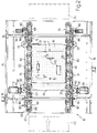
- Electronic module 11 comprises a printed circuit plate 12 (Fig.2) on which may be mounted active and/or passive components 13, and which is usually rectangular in shape and of standard size.
- Fig.2 printed circuit plate 12
- Each type of module 11 presents, on plate 12, a given grid network of test points 14.
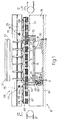
- Apparatus 10 comprises a fixed support 16 (Fig.1), known as a receiver, to which may be fitted a number of electrical connectors 17 connected at one end to a computer programmed to test a specific plate 12; and an adaptable support 18 in the form of a plate having a rectangular upper surface 15.
- a fixed support 16 Fig.1
- a receiver to which may be fitted a number of electrical connectors 17 connected at one end to a computer programmed to test a specific plate 12
- an adaptable support 18 in the form of a plate having a rectangular upper surface 15.
- Adapter 18 is mounted firmly in removable manner to receiver 16, and is fitted with a number of feelers or pins 19 arranged matching test points 14 on plate 12. By means of wires 20 and connectors 20a inside receiver 16, pins 19 are connected separately to connectors 17 on receiver 16. Adapter 18 must thus be designed for testing a specific plate 12.
- Apparatus 10 also comprises an actuator 21, which is moved towards receiver 16 for bringing test points 14 on plate 12 into contact with the tips of pins 19, as described in more detail later on.
- Plates 12 may be fed on to apparatus 10 by means of a conveyor 22, and unloaded either by means of an output conveyor 23 or back along conveyor 22.
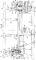
- apparatus 10 comprises an adjustable gripping device 24 on receiver 16, for receiving a test plate 12.
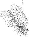
- device 24 comprises two mechanisms 25, each mounted on a metal box-section bar 26 having two vertical walls 27 and 28, and two horizontal walls 40 and 41.
- Each mechanism 25 comprises a number of grooved intermediate pulleys 31 and grooved end pulleys 32 and 33.
- Each pulley 31-33 presents a V-shaped groove 34 (Fig.s 4 to 6) engaging a respective longitudinal edge 35 of plate 12.
- the outer edges of the two end pulleys 32 and 33 present a ring gear 36.
- Each pulley 31-33 is fitted with a respective toothed pulley 42, e.g. by means of a screw 43.
- Pulleys 42 of each mechanism 25 are engaged by a toothed belt 44 so as to turn synchronously.
- Each pulley 42 is mounted for rotation on portion 37 (Fig.6) of a respective pin 38 on which it forms a shoulder 39.
- Each pin 38 presents a rounded free end, and slides axially inside two holes in horizontal walls 40 and 41 of bar 26.
- the axes of pins 38 are coplanar and perpendicular to surface 15 of adapter 18, so that the axes of pulleys 31-33 are parallel.
- Portion 37 (Fig.6) of each pin 38 of mechanism 25 is inserted inside a respective hole in a Z-section plate 46, the bent edge 47 of which is connected to the bent edge 49 of wall 27 by means of a helical spring 48 by which plate 46 is normally held resting on bottom wall 41 of bar 26.
- Each pulley 31-33 is mounted on portion 37 of respective pin 38 by means of a washer 51 and a nut 52 screwed on to the threaded end of portion 37, so that pulleys 42 are maintained contacting respective plates 46.
- Actuator 21 presents two longitudinal bars 53 (Fig.3) for respective mechanisms 25. Each bar 53 simultaneously engages the free ends of pins 38 of respective mechanism 25, so as to move pulleys 31, 32 and 33, together with pins 38 and plates 46, against the action of springs 48 (Fig.6). It will be noted that each pulley 31-33 presents a recess 54 at the bottom for housing washer 51 and threaded nut 52 flush with the bottom surface of the pulley, thus enabling mechanisms 25 to move plate 12 as close as possible to adapter 18.
- Each groove 34 on pulleys 31-33 houses a ring 55 (Fig.s 5 and 6) made of material having a high friction coefficient, so that, when pulleys 31-33 are rotated, rings 55 engage edges 29 of plate 12 so as to displace it longitudinally in slidefree manner.
- the shape and size of groove 34 are such as to position plate 12 extremely accurately, both crosswise and in height.
- Ring gear 36 of each pulley 32 meshes permanently with a respective toothed roller 56 rotating on a vertical shaft 57 supported on a bent tab portion 58 of wall 27 (Fig.6).
- the height of roller 56 is such as to enable engagement by ring gear 36 regardless of the vertical position of pulley 32.
- Roller 56 is rotated, via a pair of bevel gears 59, by a respective electric motor 61 supported on an appendix 60 of wall 27 and controlled numerically, e.g. a step motor.
- Toothed roller 56 is also engaged by ring gear 62 (Fig.s 4 and 5) of a grooved pulley 63 having a retaining ring 55.
- Pulley 63 is integral with a toothed pulley 64 with which it forms a pair identical to pair 32-42 and forming part of a drive unit indicated as a whole by 66 (Fig.2).
- Each drive unit 66 comprises a number of grooved pulleys 67, e.g. two, similar to pulleys 31 and each integral with a toothed pulley 64. Pulleys 64 are rotated simultaneously by a toothed belt 68.
- Each of grooved pulleys 63 and 67 is mounted on a shaft 69 (Fig.5) supported on wall 41 of bar 26.
- Shafts 69 are axially fixed, but keep pulleys 63 and 67 in the same horizontal plane as pulleys 31-33 in the top idle position.
- Units 66 therefore provide for transversely aligning plate 12 and transferring it from input conveyor 22 to mechanisms 25.
- Ring gear 36 of the other end pulley 33 of each mechanism 25 (Fig.s 1 to 3) in turn meshes with an idle toothed roller 72 activating a respective drive unit 73 symmetrical with unit 66 and also supported on bar 26.
- the two units 73 provide for transferring plate 12 from adapter 18 to unloading conveyor 23.
- the test apparatus operates as follows.
- Plate 12 is fed by input conveyor 22 on to the two drive units 66, where it is arrested on a locator (not shown) and centered transversely by pulleys 63 and 67 in relation to adapter 18. Both motors 61 are then operated a given number of steps, so as to each drive belts 44 and 68 via toothed roller 56 and ring gears 36 and 62 of pulleys 31 and 63.
- Plate 12 is fed on to mechanisms 25 from one of the transverse sides 30 of adapter 18, and is engaged between pulleys 31-33 by which it is moved into a position wherein test points 14 are aligned longitudinally with respective pins 19 on adapter 18.
- Actuator 21 is moved down and, by means of the two bars 53, moves all the pins 38 on mechanisms 25 simultaneously downwards against the action of springs 48 (Fig.6). Pulleys 31-33 therefore also move down into the position shown by the dotted lines in Fig.5, so as to bring test points 14 on plate 12 (Fig.s 1 to 3) into contact with respective pins 19.
- Actuator 21 is then moved back up to enable springs 48 (Fig.6) to raise plates 46 together with pins 38, pulleys 31-33 and tested plate 12.
- motors 61 (Fig.2) are again operated for driving belts 44 via roller 56; plate 12 engages the pulleys of units 73, the belts 68 of which are driven via ring gears 36 of pulleys 33 and roller 72; and the tested plate 12 is fed on to output conveyor 23.
- Receiver 16 presents two sides 75, each having two appendixes 76 (Fig.3) fitted with two round-section transverse bars 77 and 78 with teeth 79 at the bottom (Fig.s 5 and 6).
- Each bar 77 and 78 is fitted through two holes 80 and 81 in vertical walls 27 and 28 of box-section bars 26, so that bars 77 and 78 act as a transverse guide for bars 26.
- Wall 27 of both bars 26 presents two drilled appendixes 82 in which is mounted for rotation a longitudinal shaft 83.
- Each shaft 83 is fitted with two pinions 84 engaging teeth 79 of transverse bars 77 and 78, so that each bar 26 is parallel at all times with the respective longitudinal side 29 of adapter 18 (Fig.2).
- Each shaft 83 is also fitted with a helical gear 85 (Fig.6) meshing with a worm screw 86 integral with a respective hand knob 87. Worm screw 86 rotates in a seat on a tab 88 of respective drilled appendix 82.
- the respective worm screw 86 turns helical gear 85 together with respective shaft 83 and pinions 84. These therefore roll simultaneously along toothed bars 77 and 78, so as to move respective bar 26, and respective mechanism 25, transversely and parallel to itself.
- the worm screw 86-helical gear 85 pair provides for locking mechanism 25 in position and so enabling each to be adapted individually to the width and location of test plate 12.
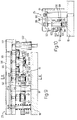
- adapter 18 of apparatus 10 is fitted in removable manner to receiver 16, and presents a drilled plate 89 (Fig.8) movable in the direction of surface 15 as described later on, and which provides for protecting and guiding pins 19 on adapter 18.
- Gripping device 24 comprises two mechanisms 25 (Fig.7), each supported on a longitudinal L-section bar 90 fitted in removable manner to adapter 18 by means of pins 91 and parallel to longitudinal side 29 of adapter 18.
- Each bar 90 is fitted with a longitudinal prismatic bar 92 in turn fitted with a section 93 sliding on two pins 94 fitted to L-section bar 90.
- Each pin 94 presents a helical compression spring 95 (Fig.s 9 and 10) for pushing section 93 upwards.
- Section 93 is fitted with a box bar 96 having an upside down U section and covering bar 90. Drilled plate 89 is integral in known manner with two bars 92.
- Each bar 92 presents a drive unit comprising a number of intermediate pulleys 97 and end pulleys 98 and 99, rotating on coplanar vertical shafts.
- Pulleys 97-99 are engaged by a polyurethane drive belt 100, which also engages an end flange 101 on each pulley 97-99.
- a polished vertical flange 102 on section 93 provides for adhering belt 100 to pulleys 97-99.
- the two longitudinal edges 35 of printed circuit plate 12 (Fig.s 7 and 8) are engaged by belts 100 of both mechanisms 25, and rest on the flat inner surface of each flange 101 (Fig.10).
- Each of end pulleys 98 and 99 also presents a toothed pinion 103, that of pulley 99 meshing with a gear 104 mounted for rotation on bar 92.
- each bar 90 may be fitted with two identical drive units, so that gear 104 of the second unit meshes with pinion 103 of pulley 98 of the first unit, thus operating both units synchronously.
- Gear 104 of the first unit meshes with pinion 105 (Fig.10) of an additional pulley 106 having a flange 107 and a groove 108 housing a ring 109 of elastic material engaging respective edge 35 of plate 12.
- Actuator 21 of apparatus 10 consists of a frame having two lateral bars 110 (Fig.8), each having at least two rods 111 engaging respective box bar 96.
- the frame also comprises intermediate bars 112 having further rods 113 directly engaging plate 12 and adjustable on rods 112 for engaging specific circuit points on plate 12.
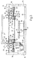
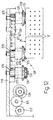
- Apparatus 10 also comprises a loading and unloading unit 114 (Fig.s 7 and 8) in turn comprising a fixed supporting plate 115 and two sides 116. Each side 116 is fitted with a structure 117 housing a respective drive unit 118 (Fig.11) comprising a reversible epicyclic geared motor 119 which, via a bevel gear pair 120, turns a gear 121 meshing with a toothed roller 122 rotating on structure 117.
- a loading and unloading unit 114 (Fig.s 7 and 8) in turn comprising a fixed supporting plate 115 and two sides 116.
- Each side 116 is fitted with a structure 117 housing a respective drive unit 118 (Fig.11) comprising a reversible epicyclic geared motor 119 which, via a bevel gear pair 120, turns a gear 121 meshing with a toothed roller 122 rotating on structure 117.
- Pinion 105 of pulley 106 meshes with an idle gear 123 rotating on bar 92 and in turn meshing with roller 122, which is so sized as to mesh with gear 123 regardless of the vertical position of bar 92.
- Unit 114 can be moved longitudinally in relation to receiver 16, and roller 122 is brought into engagement with gears 123 by simply moving unit 114 longitudinally towards gripping device 24.
- Drive unit 118 (Fig.11) is thus mounted, not on adapter 18, but on loading and unloading unit 114, thus reducing the cost of the variable equipment of apparatus 10.
- Each side 116 of unit 114 (Fig.s 7 and 12) is also fitted with a drive unit 124 comprising a number of pulleys 125 rotating on coplanar horizontal shafts, and each having a toothed pinion 126 meshing with a toothed belt 127.
- Each pulley 125 presents a flange 128 having a conical surface 129 engaging edge 35 of test plate 12; and a groove 130 housing a retaining ring 131 on which edge 35 of plate 12 rests.
- Belt 127 also engages a further toothed pulley 132 (Fig.11) pivoting on a shaft 133 so located as to only engage belt 127 on the upper side of pulleys 125.
- a belt tensioner 134 provides for adjusting the tension of belt 127.
- Pulley 132 is driven by gear 121 via a pinion 135 and a bevel gear pair 136.
- Pinion 135 is integral with a further grooved pulley 137 having a retaining ring 138 in the same horizontal plane as ring 109 of pulley 106 (Fig.9), and engages edge 35 of plate 12 (Fig.7) so as to center plate 12 in relation to mechanisms 25.
- loading and unloading unit 114 comprises a roller 139 (Fig.11) rotating on a horizontal shaft 140 fitted to a flange 141 on structure 117.
- Roller 139 provides for adhering edge 35 of plate 12 to rings 131 of pulleys 125 and to ring 109 of pulley 105.
- Belt 127 is in turn held firmly against pinions 126 (Fig.8) by a polished flange 142 fitted to respective side 116.
- the Fig.7-12 device operates as follows.
- Printed circuit plate 12 for testing may be loaded on to unit 114 (Fig.7) either manually or, for example, by means of an automatic loader, and is placed with lateral edges 35 resting on retaining rings 131 of pulleys 125 (Fig.s 11 and 12).
- the control circuit then operates geared motors 119 of both drive units 124 in such as direction as to rotate pulleys 132 anticlockwise.
- the two belts 127 thus turn all of pulleys 125 in the same direction, so that plate 12 is moved leftwards by retaining rings 131.
- the two rollers 139 hold each edge 35 of plate 12 against ring 131 of the first pulley 125 on the left, so as to engage edge 35 with ring 138 of respective horizontal pulley 137.
- the two pulleys 137 are rotated in the opposite direction for feeding plate 12 on to gripping device 24 (Fig.7) of adapter 18, through transverse side 30.
- Edges 35 of plate 12 are then driven by the drive units of mechanisms 25, via rings 109 of pulleys 105 (Fig.s 9 and 10) and belts 100, with edges 35 of plate 12 resting on the flat surface of flanges 101 and 107.
- actuator 21 After testing, actuator 21 is moved back up; springs 95 raise mechanisms 25 together with plate 12; and geared motors 119 (Fig.11) are operated in the opposite direction so as to load plate 12 on to loading and unloading unit 114 via mechanisms 25 and drive units 124.
- Each side 116 of loading and unloading unit 114 is fitted at both ends with two transverse plates 143 (Fig.s 7 and 8) having mutual guide surfaces in the form of a toothed edge 144.
- Each side 116 also slides transversely in known manner on supporting plate 115, and presents a threaded block 145 engaged by a threaded shank 146.
- This is fitted on top with a knob 147 housed partially in an opening 148 in side 116 so that it can be turned manually from the outside of side 116.
- the bottom end of shank 146 presents a washer 149 of material having a high friction coefficient, and designed to engage a clamping surface 150 on supporting plate 115.
- knobs 147 are turned for locking washers 149 and, consequently, the two sides 116, which may then be moved transversely over supporting plate 115 into the required position. The two sides 116 are then locked on surface 150 of supporting plate 115 by means of knobs 147 and washers 149.
- mechanisms 25 may be adjusted easily to the width of test plate 12, and provide for aligning and bringing plate 12 into contact with pins 19 of adapter 18, as well as for gripping, loading and unloading plate 12, thus providing for a high degree of reliability of the device.
- apparatus 10 according to the Fig.7-12 embodiment is even more economical, by virtue of mechanisms 25 being mounted in removable manner on adapter 18 itself, and being operated by the same motors as loading and unloading unit 114.
- pulleys 31-33 and 97-99 may all be the same, and a single motor 61 or 119 may be provided for both mechanisms 25.
Applications Claiming Priority (4)
| Application Number | Priority Date | Filing Date | Title |
|---|---|---|---|
| IT6771390 | 1990-09-25 | ||
| IT6771490 | 1990-09-25 | ||
| IT67714A IT1241584B (it) | 1990-09-25 | 1990-09-25 | Supporto ricevitore per apparecchiature di collaudo automatico di moduli elettronici |
| IT67713A IT1241571B (it) | 1990-09-25 | 1990-09-25 | Supporto adattatore per apparecchiature di collaudo automatico di moduli elettronici |
Publications (2)
| Publication Number | Publication Date |
|---|---|
| EP0477821A2 true EP0477821A2 (de) | 1992-04-01 |
| EP0477821A3 EP0477821A3 (de) | 1994-02-09 |
Family
ID=26329820
Family Applications (1)
| Application Number | Title | Priority Date | Filing Date |
|---|---|---|---|
| EP91116152A Withdrawn EP0477821A2 (de) | 1990-09-25 | 1991-09-23 | Handhabe-Vorrichtung für elektronische Module für ein automatisches Testgerät |
Country Status (2)
| Country | Link |
|---|---|
| US (1) | US5192907A (de) |
| EP (1) | EP0477821A2 (de) |
Cited By (1)
| Publication number | Priority date | Publication date | Assignee | Title |
|---|---|---|---|---|
| NL1007474C2 (nl) * | 1997-11-07 | 1999-05-10 | Integrated Test Engineering N | Inrichting voor het testen van elektronische schakelingen. |
Families Citing this family (14)
| Publication number | Priority date | Publication date | Assignee | Title |
|---|---|---|---|---|
| US5862040A (en) * | 1997-02-03 | 1999-01-19 | A.I.M., Inc. | Smart pallet for burn-in testing of computers |
| US6586954B2 (en) * | 1998-02-10 | 2003-07-01 | Celadon Systems, Inc. | Probe tile for probing semiconductor wafer |
| US6201402B1 (en) * | 1997-04-08 | 2001-03-13 | Celadon Systems, Inc. | Probe tile and platform for large area wafer probing |
| US6051983A (en) * | 1997-11-03 | 2000-04-18 | International Business Machines Corporation | Positive side support test assembly |
| US6046421A (en) * | 1997-11-06 | 2000-04-04 | Computer Service Technology, Inc. | PCB Adapter for a test connector assembly for an automatic memory module handler for testing electronic memory modules |
| US5973285A (en) * | 1997-11-26 | 1999-10-26 | Computer Service Technology, Inc. | Connector alignment assembly for an electronic memory module tester |
| US6433532B1 (en) * | 2000-07-07 | 2002-08-13 | Advanced Micro Devices, Inc. | Method and apparatus for mounting a load board onto a test head |
| TWI318300B (en) * | 2002-06-28 | 2009-12-11 | Celadon Systems Inc | Shielded probe apparatus for probing semiconductor wafer |
| US6975128B1 (en) | 2003-03-28 | 2005-12-13 | Celadon Systems, Inc. | Electrical, high temperature test probe with conductive driven guard |
| US7728609B2 (en) | 2007-05-25 | 2010-06-01 | Celadon Systems, Inc. | Replaceable probe apparatus for probing semiconductor wafer |
| CN109932636B (zh) * | 2019-03-19 | 2021-01-29 | 信泰电子(西安)有限公司 | 双工位电性测试装置 |
| CN113777480B (zh) * | 2021-07-30 | 2024-04-02 | 宁波金宸科技有限公司 | 一种继电器端子的上锡及检测一体设备 |
| CN115413220B (zh) * | 2022-10-12 | 2023-04-07 | 广东电邦新能源科技有限公司 | 一种电源适配器pcb板装配设备 |
| CN117471258A (zh) * | 2023-11-16 | 2024-01-30 | 河北如电电气设备有限公司 | 一种电力设备故障检测装置 |
Citations (5)
| Publication number | Priority date | Publication date | Assignee | Title |
|---|---|---|---|---|
| CH560392A5 (en) * | 1973-12-19 | 1975-03-27 | Siemens Ag Albis | Testing conductor plates having numerous soldered points etc. - plates are mounted on insulated carrier block |
| WO1985003690A1 (en) * | 1984-02-15 | 1985-08-29 | Ironics, Inc. | Flat article conveyor |
| EP0317213A2 (de) * | 1987-11-20 | 1989-05-24 | Nihon Den-Netsu Keiki Co., Ltd. | Beförderungsvorrichtung für gedruckte Leiterplatten |
| DE3738167A1 (de) * | 1987-11-10 | 1989-05-24 | Siemens Ag | Greifelement |
| EP0365418A1 (de) * | 1988-10-17 | 1990-04-25 | Osl Technologies | Förderer zum Führen von gedruckten Leiterplatten längs einer Strecke mit wechselnder Neigung |
Family Cites Families (4)
| Publication number | Priority date | Publication date | Assignee | Title |
|---|---|---|---|---|
| US4774462A (en) * | 1984-06-11 | 1988-09-27 | Black Thomas J | Automatic test system |
| US4818933A (en) * | 1986-10-08 | 1989-04-04 | Hewlett-Packard Company | Board fixturing system |
| US4771234A (en) * | 1986-11-20 | 1988-09-13 | Hewlett-Packard Company | Vacuum actuated test fixture |
| US4841231A (en) * | 1987-10-30 | 1989-06-20 | Unisys Corporation | Test probe accessibility method and tool |
-
1991
- 1991-09-23 EP EP91116152A patent/EP0477821A2/de not_active Withdrawn
- 1991-09-23 US US07/763,929 patent/US5192907A/en not_active Expired - Fee Related
Patent Citations (5)
| Publication number | Priority date | Publication date | Assignee | Title |
|---|---|---|---|---|
| CH560392A5 (en) * | 1973-12-19 | 1975-03-27 | Siemens Ag Albis | Testing conductor plates having numerous soldered points etc. - plates are mounted on insulated carrier block |
| WO1985003690A1 (en) * | 1984-02-15 | 1985-08-29 | Ironics, Inc. | Flat article conveyor |
| DE3738167A1 (de) * | 1987-11-10 | 1989-05-24 | Siemens Ag | Greifelement |
| EP0317213A2 (de) * | 1987-11-20 | 1989-05-24 | Nihon Den-Netsu Keiki Co., Ltd. | Beförderungsvorrichtung für gedruckte Leiterplatten |
| EP0365418A1 (de) * | 1988-10-17 | 1990-04-25 | Osl Technologies | Förderer zum Führen von gedruckten Leiterplatten längs einer Strecke mit wechselnder Neigung |
Cited By (1)
| Publication number | Priority date | Publication date | Assignee | Title |
|---|---|---|---|---|
| NL1007474C2 (nl) * | 1997-11-07 | 1999-05-10 | Integrated Test Engineering N | Inrichting voor het testen van elektronische schakelingen. |
Also Published As
| Publication number | Publication date |
|---|---|
| US5192907A (en) | 1993-03-09 |
| EP0477821A3 (de) | 1994-02-09 |
Similar Documents
| Publication | Publication Date | Title |
|---|---|---|
| EP0477821A2 (de) | Handhabe-Vorrichtung für elektronische Module für ein automatisches Testgerät | |
| JP3704013B2 (ja) | モジュールicハンドラーのキャリアハンドリング装置及びその方法 | |
| DE60004465T2 (de) | Transportvorrichtung für Substrate und ihr Lehrsystem | |
| EP1266234B1 (de) | Vorrichtung zum testen von leiterplatten | |
| EP1515403B1 (de) | Kabelbearbeitungseinrichtung | |
| DE3805781A1 (de) | Teile-zufuehreinrichtung fuer eine automatische leiterplatten-bestueckungsmaschine | |
| DE102008038319A1 (de) | Montagevorrichtung für elektronische Bauelemente und Montageverfahren für elektronische Bauelemente | |
| DE102008039566A1 (de) | Montagevorrichtung für elektronische Bauelemente und Montageverfahren für elektronische Bauelemente | |
| EP0468159A2 (de) | Elektronische Waage | |
| CN115575124A (zh) | 一种应用于高温轴承的自动装配检测装置 | |
| US6425178B1 (en) | Carrier for a module integrated circuit handler | |
| US4969552A (en) | Method and apparatus for inverting printed circuit boards | |
| DE19716690B4 (de) | Wärmebehandlungsvorrichtung für Halbleiterkristallscheiben | |
| CN114104677A (zh) | 基板翻转装置以及基板翻转方法 | |
| US4586247A (en) | Apparatus for inserting electronic elements | |
| KR960006515B1 (ko) | 매거진 랙 및 그 위치 조정 시스템 | |
| EP1902325B1 (de) | Testvorrichtung zum testen von elektronischen bauelementen | |
| CN218445197U (zh) | 一种带有芯片载具的自动化芯片检测设备 | |
| EP2389059B1 (de) | Bestückkopf für einen Bestückautomaten, Bestückautomat sowie Bestückverfahren | |
| US4288745A (en) | Printed circuit board testing means | |
| DE19711683A1 (de) | IC-Baustein-Montage/Demontage-System sowie ein Montage/Demontage-Kopf dafür | |
| EP0598492A1 (de) | Verfahren und Gerät zum Montieren von Verbindern | |
| KR20070052191A (ko) | 점등 검사장치 | |
| JP2008272704A (ja) | 除塵装置 | |
| KR101555336B1 (ko) | 차량용 부품 배출 장치 |
Legal Events
| Date | Code | Title | Description |
|---|---|---|---|
| PUAI | Public reference made under article 153(3) epc to a published international application that has entered the european phase |
Free format text: ORIGINAL CODE: 0009012 |
|
| AK | Designated contracting states |
Kind code of ref document: A2 Designated state(s): DE FR GB IT |
|
| PUAL | Search report despatched |
Free format text: ORIGINAL CODE: 0009013 |
|
| AK | Designated contracting states |
Kind code of ref document: A3 Designated state(s): DE FR GB IT |
|
| STAA | Information on the status of an ep patent application or granted ep patent |
Free format text: STATUS: THE APPLICATION IS DEEMED TO BE WITHDRAWN |
|
| 18D | Application deemed to be withdrawn |
Effective date: 19940810 |