EP0477730A2 - Halbtonbildverarbeitungsgerät - Google Patents
Halbtonbildverarbeitungsgerät Download PDFInfo
- Publication number
- EP0477730A2 EP0477730A2 EP91115766A EP91115766A EP0477730A2 EP 0477730 A2 EP0477730 A2 EP 0477730A2 EP 91115766 A EP91115766 A EP 91115766A EP 91115766 A EP91115766 A EP 91115766A EP 0477730 A2 EP0477730 A2 EP 0477730A2
- Authority
- EP
- European Patent Office
- Prior art keywords
- image
- density
- forming
- basis
- densities
- Prior art date
- Legal status (The legal status is an assumption and is not a legal conclusion. Google has not performed a legal analysis and makes no representation as to the accuracy of the status listed.)
- Granted
Links
Images


Classifications
-
- H—ELECTRICITY
- H04—ELECTRIC COMMUNICATION TECHNIQUE
- H04N—PICTORIAL COMMUNICATION, e.g. TELEVISION
- H04N1/00—Scanning, transmission or reproduction of documents or the like, e.g. facsimile transmission; Details thereof
- H04N1/40—Picture signal circuits
- H04N1/407—Control or modification of tonal gradation or of extreme levels, e.g. background level
- H04N1/4076—Control or modification of tonal gradation or of extreme levels, e.g. background level dependent on references outside the picture
- H04N1/4078—Control or modification of tonal gradation or of extreme levels, e.g. background level dependent on references outside the picture using gradational references, e.g. grey-scale test pattern analysis
Definitions
- the invention relates to an apparatus for processing a half tone image.
- Fig. 17 shows a schematic construction of a laser beam printer.
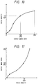
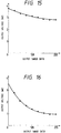
- Image data 1 is a digital signal of eight bits and shows light and dark states (256 gradations) of an image. As shown in Fig. 18, there is a linear relation between the light and dark information of the image and the gradations (0 to 255).
- a density converter 2 For the digital image signal, an input density of 256 gradations is converted into an output density of 256 gradations by a density converter 2 on the basis of a lookup table system shown in Fig. 19.
- Fig. 20 shows the relation between the input density and the output density after conversion.
- the digital image signal is again converted into the analog signal by a D/A converter 6.
- the analog signal is compared with a signal of a predetermined period which is generated from a triangular wave generating circuit 8 by a comparator 7 and is pulse width modulated.
- the pulse width modulated binary image signal is directly supplied to a laser driving circuit 9 and is used as a signal to control on/off times of the light emission of a laser diode 10.
- a laser beam emitted from the laser diode 10 is scanned in the main scanning direction by a well-known polygon mirror 11 and passes through an f- ⁇ lens 12 and is reflected by a reflecting mirror 13.
- the laser beam is subsequently irradiated onto a photo sensitive drum 14 which is rotating in the direction indicated by an arrow in Fig. 17, so that an electrostatic latent image is formed on the drum 14 as an image carrier.
- the photo sensitive drum 14 is uniformly discharged by a pre-exposing device 16 before the laser beam is irradiated. Thereafter, the drum 4 is uniformly charged to the minus polarity by a charging device 15. Subsequently, the laser beam is irradiated onto the drum 14 and the electrostatic latent image corresponding to the image signals is formed on the surface of the drum 14.
- a toner having a minus charging characteristic is deposited by a developing device 17 on the basis of a well-known inversion developing method.
- the portion on which the toner has been deposited is developed.
- a development image (toner image having minus charges) formed on the drum 14 is transferred onto a copy transfer material (generally, paper) 18 by a copy transfer charging device 19.
- the remaining toner on the surface of the drum 14 is scraped off by a cleaner.
- a density of a final image on the copy transfer material which is formed by the above processes is determined in a one to one corresponding relation for the value of the digital image data which is generated from the density converter 2.
- a light emitting time of the laser diode is specified in accordance with the value of the digital image data and a quantity of laser beam which is irradiated onto the drum 14 is decided. Further, an amount of toner which is developed, that is, an image density can be specified by causing a predetermined attenuation in a surface potential of the photo sensitive drum in accordance with the laser light quantity.
- the relation of the image density to the gradation of the digital image data which is generated is not linear but shows an S-shaped curve.
- S-shaped curve characteristics depend on a non-linearity of the sensitivity characteristic of the photo sensitive drum or the developing characteristic to the surface potential of the photo sensitive drum. The above characteristics are based on the characteristics of the conventional electrophotograph.
- the relation of the final image density to the output image data shown in Fig. 21 is always unstable due to a difference of manufacturing lots of the photo sensitive drum or developing agents, a mechanical variation of the distance between the developing device and the photo sensitive drum, or an environmental durability dependency of the photo sensitive drum or developing agent. Thus, there is a problem such that the gradation of the reproduced image is not good.
- Another object of the invention is to provide an image processing apparatus and an image processing method in which an image is formed onto a recording medium, a density of the formed image is measured, and a density conversion coefficient is formed in accordance with the result of the measurement, thereby obtaining an image of a good gradation.
- Fig. 1 shows the first embodiment of the invention and shows an example of a laser beam printer.
- reference numerals 1, 2, and 6 to 20 designate the same portions as those shown in Fig. 17.
- Reference numeral 5 denotes an RAM in which 17 digital data of 0, 16, 32, 48, ..., 240, and 255 have been stored.
- Reference numeral 4 denotes an ROM in which a control program has been stored and 21 indicates a digital data generator for generating digital data of different gradations on the basis of 17 digital data of 0, 16, 32, 48, ..., 240, and 255 stored in the RAM 5.
- Reference numeral 22 denotes a bus switch for switching an input device to either one of the digital data generator 21 and the density converter 2 and 23 indicates a light quantity detecting apparatus comprising: a laser diode 231 as a light emitting device; a photo diode 232 as a photo sensitive device; and an amplifier 233 as shown in Fig. 2.
- the light quantity detecting apparatus 23 detects a reflection light quantity from a visible image (hereinafter, referred to as a patch) formed on the photo sensitive drum 14.
- a wave length of a laser beam which is emitted from the laser diode 231 is set to 960 nm. Since a sensitivity of the drum 14 lies within a range from 780 to 800 nm, the drum 14 is hardly influenced by the laser beam.
- An A/D converter 24 converts an analog signal from the light quantity detecting apparatus 23 into a digital signal.
- Reference numeral 3 denotes a CPU serving as correcting means for correcting a density conversion coefficient of the density converter 2 in accordance with the density detected by the light quantity detecting apparatus 23.
- the output characteristics which have been made non-linear due to the non-linearity of the photo sensitive characteristics of the photo sensitive drum or the developing characteristics to the surface potential of the photo sensitive drum are made linear. That is, when characteristic diagrams shown in Figs. 18, 20, and 21 are sensitometrically arranged into the first, second, and third quadrants as shown in Fig. 3, respectively, it will be understood that the final image density to the image light/dark information in the fourth quadrant has a linear characteristic. By obtaining such linear characteristics as mentioned above, an image of a good gradation reproducibility can be obtained.
- a density conversion curve of the fourth quadrant is not linear as shown by a broken line in Fig. 3. It will be understood from the above explanation that the density conversion curve shown in Fig. 20, namely, the input/output characteristics of the density converter 2 are determined as an inverse function of the curve shown by a broken line in the fourth quadrant.
- Fig. 4 shows the relation of the patch densities D0 to D16 to the patches P0 to P16.
- the above relation corresponds to the relation of the density to the output image data which is shown by the broken line in the fourth quadrant in Fig. 3. Therefore, an inverse function of the function shown in Fig. 4 is obtained. That is, an axis of abscissa and an axis of ordinate shown in Fig. 4 are exchanged, the patch density is standardized to 0 to 255, and the data is linearly interpolated.
- Fig. 5 shows a function obtained as mentioned above.
- Fig. 6 is a flowchart showing the control procedure stored in the ROM 4 in Fig. 1.
- the bus switch 22 is switched to the side of the digital data generator 21.
- the polygon mirror 11 and the photo sensitive drum 14 are subsequently rotated.
- step S1 17 digital data of the levels 0, 16, 32, 48, ..., 240, and 255 are read out of the RAM 5.
- the read-out digital data is converted into the analog signal by the D/A converter 6.
- step S2 the analog signal is compared with a signal from a triangular wave generating circuit 8 by the comparator 7 and a pulse width modulation is performed.
- the laser driving circuit 9 drives the laser diode 10 on the basis of the pulse width modulated binary image signal.
- step S4 the laser beam emitted from the laser diode 10 is scanned in the main scanning direction by the polygon mirror 11 and passes through the f- ⁇ lens 12 and is reflected by the reflecting mirror 13. The reflected laser beam is irradiated onto the photo sensitive drum 14, so that latent images are sequentially formed on the drum 14 in correspondence to the image output levels.
- step S5 the formed latent images are developed by the developing device 17.
- Fig. 7 shows patches formed on the drum 14.
- a size of patch which is formed on the drum 14 is set to a size such that it is larger than a diameter of a light spot which is formed by the light flux from the laser diode 231 onto the drum 14 and the signal which is received by the photo diode 232 becomes sufficinetly stable. For instance, assuming that a distance between the laser diode 231 and the drum 14 is set to 5 mm, it is preferable to set the size of patch to 20 mm x 20 mm. If the size of patch is set to a large value than it is needed, an amount of toner which is consumed increases, so that such a large patch size is unpreferable.
- step S6 a light quantity from each patch is detected.
- the detecting timing of the light quantity detecting apparatus 23 to the signal generating timing of the digital data generator 21 is deviated by only the time interval from a time point when the drum 14 is exposed until a time point when the patch faces the light quantity detecting apparatus 23.
- the light quantity detecting apparatus 23 faces the patch P6 as shown in Fig. 7
- the light emitted from the laser diode 231 toward the drum 14 is reflected by the patch P6.
- the light reflected by the patch P6 is detected by the photo diode 232.
- An output voltage from the photo diode 232 is amplified by the amplifier 233.
- step S7 256 density conversion coefficients are obtained by the linear interpolation and are set into an RAM provided in the density converter 2. After completion of the above processes, the bus switch 22 is switched to the side of the density converter 2. Upon image formation, the densities are converted on the basis of the set density conversion coefficients.
- the timing to decide the density conversion coefficients is not limited to the above timing but can be also arbitrarily set.
- such a timing can be also set to either one of the timing when a main switch is turned on, the timing after the elapse of a predetermined time from the turn-on of the main switch, and the timing when a maintenance and an inspection of the image forming apparatus are executed.
- the number of reference data in the second embodiment differs from that in the first embodiment.
- the number of levels has been set to 17 levels of 0, 16, 32, 48, ..., 240, and 255.
- the number of levels is set to six levels of 0, 16, 32, 64, 128, and 256.
- the relation of the patch density to the output image data is as shown in Fig. 10. Therefore, an axis of abscissa and an axis of ordinate shown in Fig. 10 are exchanged, thereby obtaining an approximate curve shown in Fig. 11.
- gradation characteristics of the image formed by the laser beam printer are as shown in Fig. 12.
- Fig. 12 Although an error occurs due to the approximation, there is no practical problem.
- the second embodiment has been constructed as mentioned above, as compared with the first embodiment, the processing time of the patch is reduced, an amount of toner which is consumed is decreased, and deteriorations of the durability and life due to the rotation of the drum can be reduced.
- Fig. 13 shows the third embodiment of the invention and shows an example of a color image forming apparatus having four developing devices 17Y, 17M, 17C, and 17Bk containing toners of yellow, magenta, cyan, and black, respectively. Patches of the magenta, cyan, and yellow toners are formed by the color image forming apparatus. Patches of a plurality of densities are formed every color.
- Fig. 14 shows spectral characteristics of each color.
- a light quantity detecting apparatus 31 in the embodiment comprises a lamp 234, a spectral filter 235, a lens 236, the photo diode 232, and the amplifier 233.
- a white light irradiated from the lamp 234 is spectrally separated by the spectral filter 235 and is converged by the lens 236. After that, the converged light is irradiated onto the patch formed on the photo sensitive drum 14. The light reflected from the patch is detected by the photo diode 232.
- the reason why the lamp 234 is used is because a spectrum distribution of magenta or yellow has characteristics such that the infrared ray (960 nm) is reflected and a change amount of the reflection light quantity is very small.
- a wide dynamic range of the reflection light quantity cannot be obtained with respect to either one of the three color toners and the patch density cannot be accurately measured.
- the spectral filter 235 is switched to the green filter. In the case of measuring the reflection light quantity of the yellow patch, the filter 235 is switched to the blue filter. In the case of measuring the reflection light quantity of the cyan patch, the filter 235 is switched to the red filter.
- Fig. 16 shows a dynamic range of the reflection light quantity in the above case.
- a method of forming the density conversion coefficients of each color is similar to that in the first embodiment, so that an operation and an effect which are substantially similar to those in the first embodiment are derived.
- the invention is not limited to the case of using the patches of the magenta, yellow, and cyan toners but it is also possible to construct in a manner such that the density of the patch of the black toner is measured as in the first embodiment and the density conversion coefficients of four colors are formed.
- the present invention can be applicable to a black-and-white printer, a black-and-white duplicator, a color printer, a color duplicator and an image pickup apparatus which uses an electronic photograph system or a thermal transfer system etc.
- An image processing apparatus for processing a half tone image comprises: an input device to input an image signal; an image forming circuit to form an image onto a recording medium on the basis of the image signal supplied by the input device; a generator to generate a plurality of image data having different densities; a density detector to detect a density of the image formed on the recording medium by the image forming circuit on the basis of the image data generated from the generator; and a forming circuit to form a plurality of density conversion coefficients to convert the density of the image signal supplied by the input device on the basis of the densities of the plurality of images which are detected by the density detector.
Landscapes
- Engineering & Computer Science (AREA)
- Multimedia (AREA)
- Signal Processing (AREA)
- Color, Gradation (AREA)
- Facsimile Image Signal Circuits (AREA)
- Control Or Security For Electrophotography (AREA)
Applications Claiming Priority (2)
| Application Number | Priority Date | Filing Date | Title |
|---|---|---|---|
| JP246152/90 | 1990-09-18 | ||
| JP2246152A JPH04126462A (ja) | 1990-09-18 | 1990-09-18 | 画像形成装置 |
Publications (3)
| Publication Number | Publication Date |
|---|---|
| EP0477730A2 true EP0477730A2 (de) | 1992-04-01 |
| EP0477730A3 EP0477730A3 (en) | 1992-08-26 |
| EP0477730B1 EP0477730B1 (de) | 1996-05-22 |
Family
ID=17144267
Family Applications (1)
| Application Number | Title | Priority Date | Filing Date |
|---|---|---|---|
| EP91115766A Expired - Lifetime EP0477730B1 (de) | 1990-09-18 | 1991-09-17 | Halbtonbildverarbeitungsgerät |
Country Status (4)
| Country | Link |
|---|---|
| US (1) | US5406390A (de) |
| EP (1) | EP0477730B1 (de) |
| JP (1) | JPH04126462A (de) |
| DE (1) | DE69119681T2 (de) |
Cited By (9)
| Publication number | Priority date | Publication date | Assignee | Title |
|---|---|---|---|---|
| EP0515162A2 (de) * | 1991-05-21 | 1992-11-25 | Canon Kabushiki Kaisha | Bildverarbeitungsverfahren und -gerät |
| EP0596345A1 (de) * | 1992-11-04 | 1994-05-11 | Eastman Kodak Company | Laserdruckerkalibrierung |
| WO1996008916A1 (en) * | 1994-09-13 | 1996-03-21 | Apple Computer, Inc. | Method and system for analytic generation of multidimensional color lookup tables |
| US5566372A (en) * | 1994-03-25 | 1996-10-15 | Canon Kabushiki Kaisha | Image forming apparatus and method having gradation control in a dense area in which gradation characteristics are non-linear |
| EP0785667A3 (de) * | 1996-01-05 | 1998-09-30 | Canon Kabushiki Kaisha | Halbtonerzeugung mit statistischer Pixelgewichtung |
| US5856876A (en) * | 1995-04-06 | 1999-01-05 | Canon Kabushiki Kaisha | Image processing apparatus and method with gradation characteristic adjustment |
| EP0940972A2 (de) * | 1998-03-04 | 1999-09-08 | Riso Kagaku Corporation | Zweitondrucker und Verfahren zur Erzeugung von Dichtenkorrekturkurven für das Zweitondrucken |
| US6034788A (en) * | 1994-03-25 | 2000-03-07 | Canon Kabushiki Kaisha | Image forming apparatus and method |
| AU723183B2 (en) * | 1996-01-05 | 2000-08-17 | Canon Kabushiki Kaisha | Force field halftoning |
Families Citing this family (4)
| Publication number | Priority date | Publication date | Assignee | Title |
|---|---|---|---|---|
| JP3241134B2 (ja) * | 1992-12-19 | 2001-12-25 | 株式会社リコー | トナー付着量測定方法及び画像形成装置 |
| US5696604A (en) * | 1995-01-04 | 1997-12-09 | Xerox Corporation | Analytical halftone dot construction for a hyperacuity printer |
| JP3388178B2 (ja) * | 1998-04-20 | 2003-03-17 | 京セラミタ株式会社 | レーザ強度調整方法 |
| US7678385B2 (en) * | 2004-04-28 | 2010-03-16 | Biomet Manufacturing Corp. | Irradiated implantable bone material |
Citations (4)
| Publication number | Priority date | Publication date | Assignee | Title |
|---|---|---|---|---|
| DE3408336A1 (de) * | 1983-03-08 | 1984-09-13 | Canon K.K., Tokio/Tokyo | Bildreproduktionssystem |
| EP0269033A2 (de) * | 1986-11-25 | 1988-06-01 | E.I. Du Pont De Nemours And Company | Belichtungssteuerungssystem für kontinuierlich bewegten elektrographischen Film |
| US4751377A (en) * | 1985-12-27 | 1988-06-14 | Fuji Photo Film Co., Ltd. | Light beam scanning recording apparatus and method of correcting intensity of image to be recorded thereby |
| US4870506A (en) * | 1986-12-17 | 1989-09-26 | Fuji Photo Film Co., Ltd. | Color signal conversion method for image copying |
Family Cites Families (4)
| Publication number | Priority date | Publication date | Assignee | Title |
|---|---|---|---|---|
| JPH0738685B2 (ja) * | 1986-11-10 | 1995-04-26 | キヤノン株式会社 | カラ−画像記録装置 |
| JP2607490B2 (ja) * | 1986-12-09 | 1997-05-07 | キヤノン株式会社 | 画像形成装置の画質制御方法 |
| JPH0262671A (ja) * | 1988-08-30 | 1990-03-02 | Toshiba Corp | カラー編集処理装置 |
| US4985779A (en) * | 1989-09-19 | 1991-01-15 | Intergraph Corporation | Improved method and apparatus for generating halftone images |
-
1990
- 1990-09-18 JP JP2246152A patent/JPH04126462A/ja active Pending
-
1991
- 1991-09-17 DE DE69119681T patent/DE69119681T2/de not_active Expired - Lifetime
- 1991-09-17 EP EP91115766A patent/EP0477730B1/de not_active Expired - Lifetime
-
1994
- 1994-06-21 US US08/263,409 patent/US5406390A/en not_active Expired - Lifetime
Patent Citations (4)
| Publication number | Priority date | Publication date | Assignee | Title |
|---|---|---|---|---|
| DE3408336A1 (de) * | 1983-03-08 | 1984-09-13 | Canon K.K., Tokio/Tokyo | Bildreproduktionssystem |
| US4751377A (en) * | 1985-12-27 | 1988-06-14 | Fuji Photo Film Co., Ltd. | Light beam scanning recording apparatus and method of correcting intensity of image to be recorded thereby |
| EP0269033A2 (de) * | 1986-11-25 | 1988-06-01 | E.I. Du Pont De Nemours And Company | Belichtungssteuerungssystem für kontinuierlich bewegten elektrographischen Film |
| US4870506A (en) * | 1986-12-17 | 1989-09-26 | Fuji Photo Film Co., Ltd. | Color signal conversion method for image copying |
Cited By (15)
| Publication number | Priority date | Publication date | Assignee | Title |
|---|---|---|---|---|
| EP0515162A2 (de) * | 1991-05-21 | 1992-11-25 | Canon Kabushiki Kaisha | Bildverarbeitungsverfahren und -gerät |
| EP0515162A3 (en) * | 1991-05-21 | 1993-01-13 | Canon Kabushiki Kaisha | Image processing method and apparatus |
| US5572330A (en) * | 1991-05-21 | 1996-11-05 | Canon Kabushiki Kaisha | Image processing apparatus and method |
| EP0596345A1 (de) * | 1992-11-04 | 1994-05-11 | Eastman Kodak Company | Laserdruckerkalibrierung |
| US6034788A (en) * | 1994-03-25 | 2000-03-07 | Canon Kabushiki Kaisha | Image forming apparatus and method |
| US5566372A (en) * | 1994-03-25 | 1996-10-15 | Canon Kabushiki Kaisha | Image forming apparatus and method having gradation control in a dense area in which gradation characteristics are non-linear |
| US5612902A (en) * | 1994-09-13 | 1997-03-18 | Apple Computer, Inc. | Method and system for analytic generation of multi-dimensional color lookup tables |
| WO1996008916A1 (en) * | 1994-09-13 | 1996-03-21 | Apple Computer, Inc. | Method and system for analytic generation of multidimensional color lookup tables |
| US5856876A (en) * | 1995-04-06 | 1999-01-05 | Canon Kabushiki Kaisha | Image processing apparatus and method with gradation characteristic adjustment |
| EP0785667A3 (de) * | 1996-01-05 | 1998-09-30 | Canon Kabushiki Kaisha | Halbtonerzeugung mit statistischer Pixelgewichtung |
| AU723183B2 (en) * | 1996-01-05 | 2000-08-17 | Canon Kabushiki Kaisha | Force field halftoning |
| US6124844A (en) * | 1996-01-05 | 2000-09-26 | Canon Kabushiki Kaisha | Force field halftoning |
| EP0940972A2 (de) * | 1998-03-04 | 1999-09-08 | Riso Kagaku Corporation | Zweitondrucker und Verfahren zur Erzeugung von Dichtenkorrekturkurven für das Zweitondrucken |
| EP0940972A3 (de) * | 1998-03-04 | 2001-07-04 | Riso Kagaku Corporation | Zweitondrucker und Verfahren zur Erzeugung von Dichtenkorrekturkurven für das Zweitondrucken |
| US6462836B1 (en) | 1998-03-04 | 2002-10-08 | Riso Kagaku Corporation | Double-tone printer and method of making density correction curve for double-tone printing |
Also Published As
| Publication number | Publication date |
|---|---|
| EP0477730B1 (de) | 1996-05-22 |
| DE69119681T2 (de) | 1996-10-31 |
| EP0477730A3 (en) | 1992-08-26 |
| JPH04126462A (ja) | 1992-04-27 |
| US5406390A (en) | 1995-04-11 |
| DE69119681D1 (de) | 1996-06-27 |
Similar Documents
| Publication | Publication Date | Title |
|---|---|---|
| US5566372A (en) | Image forming apparatus and method having gradation control in a dense area in which gradation characteristics are non-linear | |
| JP3021538B2 (ja) | デジタル画像形成装置 | |
| EP2408189B1 (de) | Bildverarbeitungsvorrichtung und Steuerverfahren dafür | |
| US5467196A (en) | Image forming apparatus which forms halftone images mixed with characters and fine lines | |
| US4873428A (en) | Image processing apparatus using conversion means | |
| EP0477730B1 (de) | Halbtonbildverarbeitungsgerät | |
| US5313308A (en) | Image forming apparatus which changes its tone reproducing property in accordance with ambient conditions | |
| US6320605B1 (en) | Image information processing apparatus and method | |
| US5572330A (en) | Image processing apparatus and method | |
| JP3618912B2 (ja) | 画像形成装置 | |
| US5325122A (en) | Apparatus for forming digital images | |
| US5729626A (en) | Digital image forming apparatus | |
| US6055011A (en) | Image processing apparatus which performs density control for each of plural colors of recording material | |
| JP3147458B2 (ja) | デジタル画像形成法 | |
| JP3155817B2 (ja) | 画像形成装置 | |
| US5608495A (en) | Imaging density control apparatus | |
| US6006010A (en) | Digital image forming apparatus | |
| US5467195A (en) | Density adjustment in an image processing apparatus | |
| JP3312479B2 (ja) | 画像形成装置 | |
| EP0998125B1 (de) | Bilderzeugungsgerät und Steuerungsverfahren dafür | |
| JP3163888B2 (ja) | 画像形成装置のハイライト再現調整方法 | |
| JP2810365B2 (ja) | 画像形成装置 | |
| JP3306872B2 (ja) | 電子写真作像装置 | |
| JP2925175B2 (ja) | 画像処理装置 | |
| JP3021523B2 (ja) | デジタル画像形成装置 |
Legal Events
| Date | Code | Title | Description |
|---|---|---|---|
| PUAI | Public reference made under article 153(3) epc to a published international application that has entered the european phase |
Free format text: ORIGINAL CODE: 0009012 |
|
| AK | Designated contracting states |
Kind code of ref document: A2 Designated state(s): DE FR GB IT |
|
| PUAL | Search report despatched |
Free format text: ORIGINAL CODE: 0009013 |
|
| AK | Designated contracting states |
Kind code of ref document: A3 Designated state(s): DE FR GB IT |
|
| 17P | Request for examination filed |
Effective date: 19930112 |
|
| 17Q | First examination report despatched |
Effective date: 19940920 |
|
| GRAA | (expected) grant |
Free format text: ORIGINAL CODE: 0009210 |
|
| AK | Designated contracting states |
Kind code of ref document: B1 Designated state(s): DE FR GB IT |
|
| REF | Corresponds to: |
Ref document number: 69119681 Country of ref document: DE Date of ref document: 19960627 |
|
| ET | Fr: translation filed | ||
| ITF | It: translation for a ep patent filed |
Owner name: SOCIETA' ITALIANA BREVETTI S.P.A. |
|
| GRAH | Despatch of communication of intention to grant a patent |
Free format text: ORIGINAL CODE: EPIDOS IGRA |
|
| PLBE | No opposition filed within time limit |
Free format text: ORIGINAL CODE: 0009261 |
|
| STAA | Information on the status of an ep patent application or granted ep patent |
Free format text: STATUS: NO OPPOSITION FILED WITHIN TIME LIMIT |
|
| 26N | No opposition filed | ||
| REG | Reference to a national code |
Ref country code: GB Ref legal event code: IF02 |
|
| PGFP | Annual fee paid to national office [announced via postgrant information from national office to epo] |
Ref country code: IT Payment date: 20080920 Year of fee payment: 18 |
|
| PGFP | Annual fee paid to national office [announced via postgrant information from national office to epo] |
Ref country code: FR Payment date: 20080923 Year of fee payment: 18 |
|
| PGFP | Annual fee paid to national office [announced via postgrant information from national office to epo] |
Ref country code: GB Payment date: 20090923 Year of fee payment: 19 |
|
| PGFP | Annual fee paid to national office [announced via postgrant information from national office to epo] |
Ref country code: DE Payment date: 20090930 Year of fee payment: 19 |
|
| REG | Reference to a national code |
Ref country code: FR Ref legal event code: ST Effective date: 20100531 |
|
| PG25 | Lapsed in a contracting state [announced via postgrant information from national office to epo] |
Ref country code: FR Free format text: LAPSE BECAUSE OF NON-PAYMENT OF DUE FEES Effective date: 20090930 |
|
| PG25 | Lapsed in a contracting state [announced via postgrant information from national office to epo] |
Ref country code: IT Free format text: LAPSE BECAUSE OF NON-PAYMENT OF DUE FEES Effective date: 20090917 |
|
| GBPC | Gb: european patent ceased through non-payment of renewal fee |
Effective date: 20100917 |
|
| REG | Reference to a national code |
Ref country code: DE Ref legal event code: R119 Ref document number: 69119681 Country of ref document: DE Effective date: 20110401 |
|
| PG25 | Lapsed in a contracting state [announced via postgrant information from national office to epo] |
Ref country code: DE Free format text: LAPSE BECAUSE OF NON-PAYMENT OF DUE FEES Effective date: 20110401 |
|
| PG25 | Lapsed in a contracting state [announced via postgrant information from national office to epo] |
Ref country code: GB Free format text: LAPSE BECAUSE OF NON-PAYMENT OF DUE FEES Effective date: 20100917 |