EP0476947A2 - Aufzeichnungsgerät - Google Patents
Aufzeichnungsgerät Download PDFInfo
- Publication number
- EP0476947A2 EP0476947A2 EP91308417A EP91308417A EP0476947A2 EP 0476947 A2 EP0476947 A2 EP 0476947A2 EP 91308417 A EP91308417 A EP 91308417A EP 91308417 A EP91308417 A EP 91308417A EP 0476947 A2 EP0476947 A2 EP 0476947A2
- Authority
- EP
- European Patent Office
- Prior art keywords
- recording
- data
- sheet
- mode
- driving
- Prior art date
- Legal status (The legal status is an assumption and is not a legal conclusion. Google has not performed a legal analysis and makes no representation as to the accuracy of the status listed.)
- Granted
Links
Images

Classifications
-
- B—PERFORMING OPERATIONS; TRANSPORTING
- B41—PRINTING; LINING MACHINES; TYPEWRITERS; STAMPS
- B41J—TYPEWRITERS; SELECTIVE PRINTING MECHANISMS, i.e. MECHANISMS PRINTING OTHERWISE THAN FROM A FORME; CORRECTION OF TYPOGRAPHICAL ERRORS
- B41J11/00—Devices or arrangements of selective printing mechanisms, e.g. ink-jet printers or thermal printers, for supporting or handling copy material in sheet or web form
- B41J11/36—Blanking or long feeds; Feeding to a particular line, e.g. by rotation of platen or feed roller
- B41J11/42—Controlling printing material conveyance for accurate alignment of the printing material with the printhead; Print registering
-
- B—PERFORMING OPERATIONS; TRANSPORTING
- B41—PRINTING; LINING MACHINES; TYPEWRITERS; STAMPS
- B41J—TYPEWRITERS; SELECTIVE PRINTING MECHANISMS, i.e. MECHANISMS PRINTING OTHERWISE THAN FROM A FORME; CORRECTION OF TYPOGRAPHICAL ERRORS
- B41J13/00—Devices or arrangements of selective printing mechanisms, e.g. ink-jet printers or thermal printers, specially adapted for supporting or handling copy material in short lengths, e.g. sheets
- B41J13/0009—Devices or arrangements of selective printing mechanisms, e.g. ink-jet printers or thermal printers, specially adapted for supporting or handling copy material in short lengths, e.g. sheets control of the transport of the copy material
- B41J13/0018—Devices or arrangements of selective printing mechanisms, e.g. ink-jet printers or thermal printers, specially adapted for supporting or handling copy material in short lengths, e.g. sheets control of the transport of the copy material in the sheet input section of automatic paper handling systems
Definitions
- the invention relates to a recording apparatus for recording an image on a sheet in accordance with recording data.
- a pinch roller is come into pressure contact with a carrying roller and the carrying roller is driven and rotated, thereby conveying a recording sheet and executing a predetermined recording onto the conveyed recording sheet.
- a driving force of a stepping motor or the like is transferred by using a gear train and the like in order to drive the carrying roller.
- a recording head having recording elements which are constructed on a dot unit basis is driven due to the movement of a carriage, one line is recorded, and the recording sheet is conveyed by a distance of the recording of one line every completion of the one-line recording.
- the invention is made in consideration of the above drawbacks and it is an object of the invention to provide an improved recording apparatus.
- Another object of the invention is to provide a recording apparatus which can execute the driving according to the kind of recording data in the relative movement of recording means and a sheet.
- Still another object of the invention is to provide a recording apparatus which can prevent the generation of a white line, a black line, and the like upon printing of graphics or block graphic characters without deteriorating a total printing speed or noise level in the normal mode.
- Another object of the invention is to provide a recording apparatus in which in the character printing mode which is ordinarily frequently used, a sheet feeding of a high sheet feeding speed and a small sound can be realized and, in the printing mode in the case where block graphic characters are included in graphics recording data, a sheet feeding of a high feeding precision can be realized.
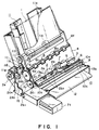
- a whole structure of an apparatus will be first described with reference to Fig. 1.
- a recording sheet 1 as a recording medium is carried by sheet carrying means 2.
- the recording sheet 1 is pressed to carrying rollers 2a by a sheet pressing member 3 so as not to be floated up from a platen 4.
- a carriage 5 When the sheet 1 is carried, a carriage 5 is reciprocated along a guide rail 6. An image is recorded onto the sheet 1 by driving recording means 7. The sheet 1 after completion of the recording is discharged by discharging means 8.
- a driving force of a carriage motor 9 as a driving source is transferred to the carriage 5 through a timing belt 10c constructing transfer means 10, so that the carriage 5 is reciprocated.
- the sheet carrying means 2 carries the recording sheet 1 to the recording means 7.
- a recording sheet which has been fed from an ASF (Auto Sheet Feeder) 11 which is detachably attached to the recording apparatus or a recording sheet which has manually been inserted from a hand inserting port 12 is carried by the sheet carrying means 2.
- the sheet carrying means 2 in the embodiment rotates the carrying rollers 2a in the direction indicated by an arrow a and carries the recording sheet 1 by front pinch rollers 2b1 and rear pinch rollers 2b2 which are rotated in association with the rotation of the carrying rollers 2a.
- a plurality of carrying rollers 2a are attached to a roller shaft 2c whose both edges are rotatably supported to left and right side walls 13a and 13b of the frame of the apparatus.
- a driving force from a carrier motor 2e is transferred to the roller shaft 2c by a driving transfer structure of the gear train mentioned above.
- a carrying gear 2d1 is attached to the roller shaft 2c.
- the gear 2d1 is in engagement with an idler gear 2d2.
- the idler gear 2d2 is in engagement with a first transfer gear 2d3.
- a second transfer gear 2d4 is attached to a shaft of the first transfer gear 2d3.
- the driving force from the carrier motor 2e is selectively transferred to the first and second transfer gears 2d3 and 2d4 by a clutch mechanism (not shown).
- the front and rear pinch rollers 2b1 and 2b2 are come into pressure contact with the surfaces of the carrying rollers 2a by a spring or the like (not shown), respectively, and are attached so as to be rotated in association with the rotation of the carrying rollers 2a. Therefore, the carrying force is applied to the recording sheet 1 because the sheet 1 is nipped by the carrying rollers 2a and the pinch rollers 2b1 and 2b2 which are rotating.
- a paper pan which is curved along peripheral surfaces of the carrying rollers 2a is attached below the carrying rollers 2a.
- the paper pan is extended until the hand inserting port 12 and functions as a down guide of the recording sheet 1 which has manually been inserted.
- upper guide plates are attached above the paper pan with a predetermined distance, thereby constructing a carrying path of the recording sheet 1.
- the recording sheet 1 which has been fed from the ASF 11 is nipped by the front pinch rollers 2b1 and the carrying rollers 2a and is turned back and carried like a U-character shape along the peripheral surfaces of the carrying rollers 2a. Further, the sheet 1 is subsequently nipped by the rear pinch rollers 2b2 and the carrying rollers 2a and is carried to a recording position locating at an upper position.
- the recording sheet 1 which has been fed from the hand inserting port 12 is nipped by the carrying rollers 2a and the rear pinch rollers 2b2 and is carried to the recording position.
- the ASF 11 to automatically feed the recording sheet 1 to the carrying means 2 will now be simply explained.
- the ASF 11 is detachably attached to the recording apparatus.
- the top sheet 1 is pressed to separating rollers 11c by a pressing spring.
- the separating rollers 11c rotate in the direction of an arrow b, one of the sheets in the top layer is separated and fed and is come into contact with nipping portions between resist rollers arranged in the downstream of the cassette 11a and the upper rollers which are in pressure contact with the resist rollers.
- the resist rollers rotate, the recording sheet 1 is nipped by the resist rollers and the upper rollers which are rotated in association with the rotation of the resist rollers and is fed to the sheet carrying means 2.
- a resist gear 11g is attached to a roller shaft 11f to which the resist rollers are attached and the resist gear 11g is in engagement with the idler gear 2d2 through an idler gear 11g1.
- a separating gear 11i is attached to a roller shaft 11h to which the separating rollers 11c are attached and idler gears 11j and 11k are sequentially in engagement with the gear 11i. Further, a gear 11l attached to the same shaft as that of the idler gear 11k is in engagement with the second transfer gear 2d4.
- the sheet pressing member 3 presses the recording sheet 1 carried by the carrying means 2 to the carrying rollers 2, thereby preventing the recording sheet 1 from floating up from the platen 4.
- the sheet pressing member 3 is made of a single plate-like member whose width is wider than a moving range of the carriage 5 so as to press the whole width region of the recording sheet 1 and is in pressure contact with the carrying rollers 2a by pressing means such as a spring or the like (not shown).
- a front edge of the sheet pressing member 3 is lcoated below the recording position by the recording means 7.
- the carried recording sheet 1 is pressed to the carrying rollers 2a by the member 3.
- the recording sheet 1 at the recording position doesn't float up from the platen 4.
- the carriage 5 is used to reciprocate the recording means 7 in the width direction of the recording sheet 1.
- the carriage 5 is slidably attached to the guide rail 6 whose both ends are fixed to the left and right side walls 13a and 13b and which functions as a guide member having a circular cross section.
- the carriage 5 is attached so as to be rotatable around the guide rail 6 as a rotational shaft and is attached so that the front side of the carriage 5, that is, the side which faces the recording sheet 1 is inclined forward and downward.
- the front edge portion of the carriage is come into pressure contact with the sheet pressing member 3 by dead weights of the carriage 5 and the recording means 7 mounted on the carriage 5.
- the driving force of the carriage motor 9 is transferred to the carriage 5 by the transfer means 10 and the carriage 5 is reciprocated.
- a driving pulley 10a is attached to one end of the moving range of the carriage 5 and a driven pulley 10b is attached to the other end.
- the carriage motor 9 is coupled to the driving pulley 10a.
- the endless timing belt 10c serving as a transfer member is rove between the pulleys 10a and 10b in parallel with the guide rail 6. A part of the timing belt 10c is fixed to the carriage 5.
- the recording means is mounted to the carriage 5 and records an ink image onto the recording sheet 1 which has been carried by the carrying means 2.
- An ink jet recording system is preferably used as recording means in the apparatus.
- the ink jet recording system comprises: liquid emitting ports each for emitting and spouting an ink liquid for recording as a flying liquid droplet; liquid channels communicated with the emitting ports; and emitting energy generating means each of which is provided in a part of the liquid channel and generates a emitting energy to form a flying liquid droplet of the ink liquid in the liquid channel.
- the emitting energy generating means is driven in accordance with an image signal and the ink liquid droplets are emitted, thereby recording an image.
- emitting energy generating means for instance, it is possible to use either one of a method using a pressure energy generating means such as an electrical/mechanical transducing element such as a piezoelectric element or the like, a method using an electromagnetic energy generating means for generating a flying liquid droplet by irradiating an electromagnetic wave of a laser beam or the like and for allowing the electromagnetic wave to be absorbed into an ink liquid, a method using thermal energy generating means such as an electrothermal transducing element, and the like.
- the method using the thermal energy generating means such as an electrothermal transducing element or the like is preferable because the emitting ports can be arranged at a high density and the recording head can be constructed in a compact size.
- ink liquids are emitted by such a method.
- Capping means 16 is provided in a left edge portion in the moving range of the carriage 5.
- the capping means 16 has a function to cover the ink emitting surfaces of the recording head 7 in the non-recording mode or the like, thereby preventing that the inks near ink emitting ports of the recording head 7 are dried or that the inks are solidified due to such a dry.
- a pump (not shown) is connected to the capping means 16.
- the pump is driven to eliminate a defective emission of the ink, or to prevent them.
- the ink is sucked from the emitting port by a sucking force of the pump, thereby executing a recovering process.
- the discharging means 8 is used to discharge the recording sheet which has been recorded by the recording means 7.
- the discharging means 8 comprises discharging rollers 8a and spurs which are in contact therewith.
- a discharging gear 8d is attached to the edge portion of a roller shaft 8c of the discharging rollers 8a.
- the discharging gear 8d is in engagement with the idler gear 2d2.
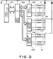
- Fig. 2 is a block diagram showing a control section of the recording apparatus shown in Fig. 1.
- Reference numeral 101 denotes a host computer to transmit print data and various kinds of control signals and 102 indicates a CPU for executing a communication control with the host computer 101 and a sequence control of the recording apparatus.
- the CPU 102 mainly comprises a well-known one-chip microcomputer having therein an ROM, an RAM, and the like.
- Reference numeral 103 denotes a head driver to drive a heat generating element as emitting energy generating means of the recording means 7; 104 a carrier motor driver to drive the carrier motor 2e; and 105 a carriage motor driver to drive the carriage motor 9.
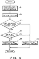
- Fig. 3 is a flowchart showing a flow of the control which is executed by the CPU 102.
- a program according to the flowchart has been stored in the ROM in the CPU 102.
- the CPU 102 receives data sent from the host computer 101 in step S1.
- the data includes characters, BGC, graphics data for an image printing, or the like.
- the data of one line is printed in step S2.
- a driving signal is sent from the CPU 102 to the carriage motor driver 105. While the carriage mtoor 9 is being moved, a signal for recording is sent to the head driver 103.
- the energy generating means (heat generating element) of the recording head 7 is driven, thereby printing the data of one line.
- a sheet feed amount before the next line is printed is discriminated.
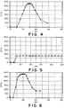
- a stepping motor is used as a carrier motor and the carrier motor 2e is driven by 15 steps in order to feed the recording sheet by 1/6 inch. For instance, as shown in Fig. 4, seven steps are used for through up and seven steps are used for through down.
- an exis of abscissa denotes an elapsed time and an axis of ordinate indicates a driving speed (for instance, a unit is PPS (Pulses Per Second) or the like of the carrier motor 2e.
- a mark ⁇ denotes a speed for the elapsed time of every step.
- the carrier motor 2e is driven while gradually increasing the speed in the former half seven steps.
- the carrier motor 2e is driven while gradually decreasing the speed in the latter half seven steps.
- such a driving method denotes that a phase excitation switching time is first set to a long time and is set to the shortest time after seven steps and that the switching time is again set to a long time after that.
- the carrier motor 2e is driven without using the table which can be used for a distance of 1/6 inch or more.
- a sheet feed amount is ordinarily set to 12/90 inch.
- the carrier motor 2e is driven by 12 steps.
- step S3 in the case of the graphics printing, the answer is NO and step S6 follows.
- step S4 a check is made in step S4 to see if a BGC is included in the printing data or not. If NO, a sheet feeding by the through up/down, for instance, a sheet feeding using the curve shown in Fig. 4 is executed in step S5. If a BGC is included, a sheet feeding is executed by using another driving curve in step S6, that is, in the embodiment, by the constant driving in a manner similar to the case of the graphics printing.
- the constant driving is executed by switching the phases by a curve shown in Fig. 5.
- the carrier motor is driven at a constant speed of 160 PPS.
- a time which is required to feed the sheet of the same amount, for instance, by 1/6 inch is equal to 60 msec or less in the through up/down mode and is equal to 100 ms in the constant mode.
- the time in the constant mode is fairly longer than that in the through up/down mode.
- the value of 160 PPS has been set on the basis of the results of the measurements of sheet feeding precisions at respective speeds.
- the sound is silent than the case in the constant mode.
- the time in the through up/down mode is shorter than that in the constant mode as mentioned above.
- the sheet feeding precision in the constant mode is higher than that in the through up/down mode.
- the sheet feeding time is long and the sound is generated in the case of printing graphics or BGC, the sheet is fed at a high precision. In the case of the ordinary character printing, the sheet can be fed in a short time and with a small sound.
- the sheet can be fed at a higher precision without largely changing the sheet feeding time and the sound generation.
- the phase switching time of the last two steps is equalized to the phase switching time in the constant mode shown in Fig. 5.
- the sheet feeding precision depends on a stationary state of the motor.
- a phenomenon such that the sheet feeding precision is largely influenced in the latter half portion of the sheet feeding operation.
- a discriminating step S10 can be also inserted between steps S3 and S4 in Fig. 6, thereby discriminating whether the sheet feed amount is just equal to 1/6 inch or not.
- the BGC is a character such that ruled lines or the like when forming, e.g., a table can be formed by a method similar to that of a character.
- a height of BGC is set to 1/6 inch. Therefore, by feeding the sheet on a 1/6 inch unit basis, the BGC of the upper line and the BGC of the lower line are vertically connected, so that a vertical ruled line or the like can be formed. Accordingly, even if a BGC exists on a certain line, for instance, the BGC is not vertically connected in the case of the sheet feeding operation in which the next sheet feed amount is larger than 1/6 inch. Thus, a high precision is unnecessary.
- the sheet feeding method in which an importance is paid to the precision is used only in the case where a BGC exists and the sheet feed amount is equal to 1/6 inch.
- the through up/down system has been used in theordinary character printing mode and the constant system has been used in the BGC or graphics printing mode.
- the through up/down system is used when a high speed of a certain degree is necessary or the like and a system different from that in the ordinary character printing mode may be used.
- the driving speed of the driving means for driving the relative moving means for relatively moving the recording means and the sheet is controlled by different modes in accordance with the kind of recording data, so that the recording means and the sheet can be relatively moved by paying an importance to the elements which are needed in each recording data printing mode.
- the relative movement in which a precision is set to a relatively low value and an importance is paid to both of the speed and the sound is executed.
- the graphics printing mode a relative movement in which an importance is paid to a precision than a speed and a sound can be performed.
- a silent printing can be realized without deteriorating a throughput.
- a printing can be performed without a white line, a black line, or the like.
- the invention provides an excellent effect in a recording apparatus of the ink jet system for recording by forming flying liquid droplets by using a thermal energy, praticularly, among the ink jet recording systems.
- the above system can be applied to any one of what are called on-demand type and continuous type.
- at least one driving signal which corresponds to recording information and causes a sudden temperature increase exceeding a nucleus boiling is applied to an electrothermal transducing element arranged in correspondence to a sheet or a liquid channel in which a liquid (ink) is held, thereby cuasing a thermal energy to be generated in the electrothermal transducing element.
- a film boiling is caused on a heat acting surface of the recording head.
- an air bubble in the liquid (ink) corresponding to the driving signal in a one-to-one corresponding relation can be formed. Therefore, the above system is effective.
- the liquid (ink) is emitted through an emititng port by the growth and contraction of the air bubble, thereby forming at least one liquid droplet.
- a pulse-shaped signal as a driving signal, the growth and contraction of the air bubble are quickly properly executed, so that the emission of the liquid (ink) having, particularly, an excellent response speed can be accomplished. Therefore, the use of such a pulse signal is more preferable.
- a pulse-shaped driving signal it is suitable to use a signal disclosed in the specifications of U.S. Patent Nos. 4463359 and 4345262.
- a further excellent recording can be performed by using the conditions disclosed in the specification of U.S. Patent Serial No. 4313124 of the invention regarding the temperature rising rate on the heat acting surface.
- the recording head in addition to the combination structure (linear liquid channel or right-angled liquid channel) of the emitting port, liquid channel, and electrothermal transducing element as disclosed in each of the above specifications, it is also possible to use a structure in which the heat acting portion is arranged in a benting region as disclosed in the specifications of U.S. Patent Nos. 4558333 and 4459600.
- JP-A-59-123670 a structure in which a slit common to a plurality of electrothermal transducing elements is used as an emititng port of the electrothermal transducing elements as disclosed in JP-A-59-123670 or a structure in which an opening which absorbs a pressure wave of a thermal energy is made correspond to the emitting port as disclosed in JP-A-59-138461.
- a recording head of the full-line type having a length corresponding to a width of the maximum recording medium which can be recorded by the recording apparatus.
- a recording head it is possible to use a recording head having either a structure in which such a long length is satisfied by a combination of a plurality of recording heads as disclosed in the above specifications or a structure as a single recording head which is integratedly formed.
- the invention is also effective in the case of using a recording head of an exchangeable chip type which can be electrically connected to the apparatus main body or to which the ink can be supplied from the apparatus main body by being attached to the apparatus main body or the case of using a recording head of the cartridge type in which an ink tank is provided integratedly in the recording head itself.
- recovering means spare auxiliary means, and the like to the recording head is preferable since the recording operation can be further stabilized.
- capping means for the recording head cleaning means, pressurizing or sucking means, and preheating means by an electrothermal transducing element or another heating element different therefrom or a combination thereof. It is also possible to execute a preemitting mode for performing another emission different from the recording.
- the above means and method are also effective to execute the stable recording.
- the recording mode of the recording apparatus is not limited to the recording mode of only a main color such as black or the like but the recording head is integratedly constructed or can be also realized by a combination of a plurality of recording heads. It is also possible to use an apparatus having a plurality of different colors or at least one of mixed full colors.
- the explanation has been made with respect to the case of the liquid ink.
- an ink which is solidified at a room temperature or less an ink which is softened at a room temperature, or an ink which is a liquid at a room temperature.
- the ink-jet system it is a general way that the ink itself is adjusted within a temperature range from 30°C to 70°C and a temperature control is executed so that a viscosity of the ink lies within a stable emitting range. Therefore, it is sufficient that the ink is in a liquid state when a using recording signal is applied.
- a temperature elevation due to a thermal energy is positively used as an energy of a state change from a solid state of the ink to a liquid state, thereby preventing solidification of the ink.
- the ink which is solidified in a leaving state is used to prevent the evaporation of the ink.
- an ink having a characteristic such that it is liquefied by a thermal energy for the first time such as ink which is liquefied by applying a thermal energy in accordance with the recording signal and is emitted as a liquid ink, ink such that the solidification has already been started at a time point when it reaches the recording medium, or the like.
- the ink is held as a liquid or solid matter in concave portions or through holes of a porous sheet and in such a state, the ink faces the electrothermal transducing element as disclosed in JP-A-54-56847 or JP-A-60-71260.
- the foregoing film boiling system is the most effective method for each of the above inks.
- a style of the recording apparatus of the invention is not limited to a style in which the recording apparatus is integratedly or separately installed as an image output terminal of an information processing apparauts such as word processor, computer, or the like as mentioned above.
- the invention can be also applied to a copying apparatus in combination with a reader or the like or a facsimile apparatus having transmitting and receiving functions.
Landscapes
- Ink Jet (AREA)
- Handling Of Cut Paper (AREA)
- Handling Of Sheets (AREA)
- Character Spaces And Line Spaces In Printers (AREA)
- Accessory Devices And Overall Control Thereof (AREA)
- Facsimiles In General (AREA)
Applications Claiming Priority (2)
| Application Number | Priority Date | Filing Date | Title |
|---|---|---|---|
| JP252271/90 | 1990-09-21 | ||
| JP25227190A JP3228476B2 (ja) | 1990-09-21 | 1990-09-21 | 記録装置 |
Publications (3)
| Publication Number | Publication Date |
|---|---|
| EP0476947A2 true EP0476947A2 (de) | 1992-03-25 |
| EP0476947A3 EP0476947A3 (en) | 1992-09-09 |
| EP0476947B1 EP0476947B1 (de) | 1997-01-08 |
Family
ID=17234920
Family Applications (1)
| Application Number | Title | Priority Date | Filing Date |
|---|---|---|---|
| EP91308417A Expired - Lifetime EP0476947B1 (de) | 1990-09-21 | 1991-09-16 | Aufzeichnungsgerät |
Country Status (7)
| Country | Link |
|---|---|
| US (1) | US5469197A (de) |
| EP (1) | EP0476947B1 (de) |
| JP (1) | JP3228476B2 (de) |
| KR (1) | KR0131585B1 (de) |
| CN (1) | CN1027243C (de) |
| DE (1) | DE69124044T2 (de) |
| ES (1) | ES2095297T3 (de) |
Cited By (1)
| Publication number | Priority date | Publication date | Assignee | Title |
|---|---|---|---|---|
| US6065830A (en) * | 1992-09-18 | 2000-05-23 | Canon Kabushiki Kaisha | Recording apparatus for recording at different recording speeds |
Families Citing this family (9)
| Publication number | Priority date | Publication date | Assignee | Title |
|---|---|---|---|---|
| CN1064602C (zh) * | 1992-10-14 | 2001-04-18 | 伟大科技股份有限公司 | 高容量送纸器 |
| KR0184571B1 (ko) * | 1996-10-16 | 1999-05-15 | 삼성전자주식회사 | 잉크 젯 프린터의 용지걸림 방지 구조 |
| US6056454A (en) | 1998-10-05 | 2000-05-02 | Gerber Technology, Inc. | Method and apparatus for printing on a continuously moving sheet of work material |
| JP4497639B2 (ja) * | 1999-04-06 | 2010-07-07 | キヤノン株式会社 | 記録装置 |
| JP2005255389A (ja) * | 2004-03-15 | 2005-09-22 | Fuji Photo Film Co Ltd | プリンタ |
| JP4229036B2 (ja) * | 2004-09-29 | 2009-02-25 | ブラザー工業株式会社 | 画像記録装置、及び被記録媒体の先端部の位置合わせ方法 |
| KR100744066B1 (ko) * | 2005-06-27 | 2007-07-30 | 삼성전자주식회사 | 화상형성기의 동력전달장치, 이를 구비한 화상형성기, 및 화상형성기의 동력전달방법 |
| JP5528908B2 (ja) * | 2010-06-01 | 2014-06-25 | 株式会社Pfu | 画像読取装置 |
| CN102529455A (zh) * | 2011-12-28 | 2012-07-04 | 艾塔斯科技(镇江)有限公司 | 一种打印机及其打印速度的控制方法 |
Family Cites Families (20)
| Publication number | Priority date | Publication date | Assignee | Title |
|---|---|---|---|---|
| US4097873A (en) * | 1977-02-28 | 1978-06-27 | International Business Machines Corporation | Ink jet printer for selectively printing different resolutions |
| CA1127227A (en) * | 1977-10-03 | 1982-07-06 | Ichiro Endo | Liquid jet recording process and apparatus therefor |
| JPS5936879B2 (ja) * | 1977-10-14 | 1984-09-06 | キヤノン株式会社 | 熱転写記録用媒体 |
| US4224628A (en) * | 1978-08-31 | 1980-09-23 | The Valeron Corporation | General purpose combined alphanumeric/graphics printer |
| US4330787A (en) * | 1978-10-31 | 1982-05-18 | Canon Kabushiki Kaisha | Liquid jet recording device |
| US4345262A (en) * | 1979-02-19 | 1982-08-17 | Canon Kabushiki Kaisha | Ink jet recording method |
| US4463359A (en) * | 1979-04-02 | 1984-07-31 | Canon Kabushiki Kaisha | Droplet generating method and apparatus thereof |
| US4313124A (en) * | 1979-05-18 | 1982-01-26 | Canon Kabushiki Kaisha | Liquid jet recording process and liquid jet recording head |
| US4558333A (en) * | 1981-07-09 | 1985-12-10 | Canon Kabushiki Kaisha | Liquid jet recording head |
| JPS5856085A (ja) * | 1981-09-29 | 1983-04-02 | Toshiba Corp | 印字制御方式 |
| JPS59123670A (ja) * | 1982-12-28 | 1984-07-17 | Canon Inc | インクジエツトヘツド |
| JPS59138461A (ja) * | 1983-01-28 | 1984-08-08 | Canon Inc | 液体噴射記録装置 |
| JPS6069516A (ja) * | 1983-09-26 | 1985-04-20 | Toshiba Corp | 記録計 |
| JPS6071260A (ja) * | 1983-09-28 | 1985-04-23 | Erumu:Kk | 記録装置 |
| JPS60116488A (ja) * | 1983-11-30 | 1985-06-22 | Fujitsu Ltd | 印字位置制御装置 |
| JPS61195853A (ja) * | 1985-02-27 | 1986-08-30 | Fujitsu Ltd | インクジエツトプリンタ |
| JPS62159A (ja) * | 1985-06-26 | 1987-01-06 | Brother Ind Ltd | フアクシミリ装置 |
| US4728968A (en) * | 1985-08-30 | 1988-03-01 | Siemens Aktiengesellschaft | Arrangement of discharge openings in a printhead of a multi-color ink printer |
| JPS62119074A (ja) * | 1985-11-19 | 1987-05-30 | Toshiba Corp | 印刷装置 |
| US4734868A (en) * | 1986-07-21 | 1988-03-29 | Vfn Technology Inc. | Precision paper transport system |
-
1990
- 1990-09-21 JP JP25227190A patent/JP3228476B2/ja not_active Expired - Fee Related
-
1991
- 1991-09-16 ES ES91308417T patent/ES2095297T3/es not_active Expired - Lifetime
- 1991-09-16 EP EP91308417A patent/EP0476947B1/de not_active Expired - Lifetime
- 1991-09-16 DE DE69124044T patent/DE69124044T2/de not_active Expired - Fee Related
- 1991-09-20 KR KR1019910016543A patent/KR0131585B1/ko not_active Expired - Fee Related
- 1991-09-21 CN CN91108498A patent/CN1027243C/zh not_active Expired - Fee Related
-
1993
- 1993-09-01 US US08/115,126 patent/US5469197A/en not_active Expired - Fee Related
Cited By (2)
| Publication number | Priority date | Publication date | Assignee | Title |
|---|---|---|---|---|
| US6065830A (en) * | 1992-09-18 | 2000-05-23 | Canon Kabushiki Kaisha | Recording apparatus for recording at different recording speeds |
| US6575568B1 (en) | 1992-09-18 | 2003-06-10 | Canon Kabushiki Kaisha | Recording apparatus |
Also Published As
| Publication number | Publication date |
|---|---|
| CN1061936A (zh) | 1992-06-17 |
| KR920006877A (ko) | 1992-04-28 |
| JPH04129774A (ja) | 1992-04-30 |
| ES2095297T3 (es) | 1997-02-16 |
| DE69124044D1 (de) | 1997-02-20 |
| CN1027243C (zh) | 1995-01-04 |
| JP3228476B2 (ja) | 2001-11-12 |
| KR0131585B1 (ko) | 1998-04-11 |
| EP0476947A3 (en) | 1992-09-09 |
| DE69124044T2 (de) | 1997-05-15 |
| US5469197A (en) | 1995-11-21 |
| EP0476947B1 (de) | 1997-01-08 |
Similar Documents
| Publication | Publication Date | Title |
|---|---|---|
| EP0664221B1 (de) | Seriendrucker mit offenem Regelkreis | |
| EP0630750B1 (de) | Aufzeichnungsgerät mit einer Abweichungseinstellvorrichtung | |
| US6203139B1 (en) | Carriage random vibration | |
| CN1055897A (zh) | 一种记录装置 | |
| EP0476947B1 (de) | Aufzeichnungsgerät | |
| US6260945B1 (en) | Recording apparatus and method for controlling scanning speeds of the recording head of such recording apparatus | |
| US5309180A (en) | Ink jet recording apparatus and recovering mechanism thereof | |
| EP0469854B1 (de) | Steuerung für einen Drucker | |
| EP0661165B1 (de) | Aufzeichnungsgerät | |
| JPH0930073A (ja) | 記録媒体および印刷装置 | |
| EP0539156B1 (de) | Blattzuführvorrichtung für Aufzeichnungsgerät | |
| JPH06115097A (ja) | インクジェット記録装置 | |
| US20030174194A1 (en) | Image forming apparatus | |
| JP3308602B2 (ja) | 記録装置 | |
| US6008824A (en) | Recording apparatus including feeding mechanism with exhausting roller connected to sheet guide member | |
| JPH04368877A (ja) | 画像形成装置 | |
| JPH0781047A (ja) | 記録装置および該記録装置を備えた情報処理システム | |
| JPH0569610A (ja) | 記録装置 | |
| JPH06262831A (ja) | 記録装置 | |
| JP2753128B2 (ja) | 画像形成装置 | |
| JP3045738B2 (ja) | 記録装置および記録方法 | |
| JPH0516476A (ja) | ロール紙カートリツジおよび該ロール紙カートリツジを備えた記録装置 | |
| JPH09116686A (ja) | インクジェット記録装置 | |
| JPH0872359A (ja) | 記録装置 | |
| JPH07177325A (ja) | 記録装置 |
Legal Events
| Date | Code | Title | Description |
|---|---|---|---|
| PUAI | Public reference made under article 153(3) epc to a published international application that has entered the european phase |
Free format text: ORIGINAL CODE: 0009012 |
|
| AK | Designated contracting states |
Kind code of ref document: A2 Designated state(s): BE DE ES FR GB IT NL |
|
| PUAL | Search report despatched |
Free format text: ORIGINAL CODE: 0009013 |
|
| AK | Designated contracting states |
Kind code of ref document: A3 Designated state(s): BE DE ES FR GB IT NL |
|
| 17P | Request for examination filed |
Effective date: 19930125 |
|
| 17Q | First examination report despatched |
Effective date: 19940406 |
|
| GRAH | Despatch of communication of intention to grant a patent |
Free format text: ORIGINAL CODE: EPIDOS IGRA |
|
| GRAH | Despatch of communication of intention to grant a patent |
Free format text: ORIGINAL CODE: EPIDOS IGRA |
|
| GRAA | (expected) grant |
Free format text: ORIGINAL CODE: 0009210 |
|
| ITF | It: translation for a ep patent filed | ||
| AK | Designated contracting states |
Kind code of ref document: B1 Designated state(s): BE DE ES FR GB IT NL |
|
| PG25 | Lapsed in a contracting state [announced via postgrant information from national office to epo] |
Ref country code: BE Effective date: 19970108 |
|
| REG | Reference to a national code |
Ref country code: ES Ref legal event code: FG2A Ref document number: 2095297 Country of ref document: ES Kind code of ref document: T3 |
|
| REF | Corresponds to: |
Ref document number: 69124044 Country of ref document: DE Date of ref document: 19970220 |
|
| ET | Fr: translation filed | ||
| PLBE | No opposition filed within time limit |
Free format text: ORIGINAL CODE: 0009261 |
|
| STAA | Information on the status of an ep patent application or granted ep patent |
Free format text: STATUS: NO OPPOSITION FILED WITHIN TIME LIMIT |
|
| 26N | No opposition filed | ||
| REG | Reference to a national code |
Ref country code: GB Ref legal event code: IF02 |
|
| PGFP | Annual fee paid to national office [announced via postgrant information from national office to epo] |
Ref country code: ES Payment date: 20050915 Year of fee payment: 15 |
|
| PGFP | Annual fee paid to national office [announced via postgrant information from national office to epo] |
Ref country code: GB Payment date: 20060918 Year of fee payment: 16 |
|
| PGFP | Annual fee paid to national office [announced via postgrant information from national office to epo] |
Ref country code: NL Payment date: 20060921 Year of fee payment: 16 |
|
| PGFP | Annual fee paid to national office [announced via postgrant information from national office to epo] |
Ref country code: IT Payment date: 20060930 Year of fee payment: 16 |
|
| PGFP | Annual fee paid to national office [announced via postgrant information from national office to epo] |
Ref country code: DE Payment date: 20061122 Year of fee payment: 16 |
|
| GBPC | Gb: european patent ceased through non-payment of renewal fee |
Effective date: 20070916 |
|
| PG25 | Lapsed in a contracting state [announced via postgrant information from national office to epo] |
Ref country code: NL Free format text: LAPSE BECAUSE OF NON-PAYMENT OF DUE FEES Effective date: 20080401 |
|
| NLV4 | Nl: lapsed or anulled due to non-payment of the annual fee |
Effective date: 20080401 |
|
| PG25 | Lapsed in a contracting state [announced via postgrant information from national office to epo] |
Ref country code: DE Free format text: LAPSE BECAUSE OF NON-PAYMENT OF DUE FEES Effective date: 20080401 |
|
| REG | Reference to a national code |
Ref country code: FR Ref legal event code: ST Effective date: 20080531 |
|
| PG25 | Lapsed in a contracting state [announced via postgrant information from national office to epo] |
Ref country code: FR Free format text: LAPSE BECAUSE OF NON-PAYMENT OF DUE FEES Effective date: 20071001 |
|
| PGFP | Annual fee paid to national office [announced via postgrant information from national office to epo] |
Ref country code: FR Payment date: 20060926 Year of fee payment: 16 |
|
| PG25 | Lapsed in a contracting state [announced via postgrant information from national office to epo] |
Ref country code: GB Free format text: LAPSE BECAUSE OF NON-PAYMENT OF DUE FEES Effective date: 20070916 |
|
| REG | Reference to a national code |
Ref country code: ES Ref legal event code: FD2A Effective date: 20070917 |
|
| PG25 | Lapsed in a contracting state [announced via postgrant information from national office to epo] |
Ref country code: ES Free format text: LAPSE BECAUSE OF NON-PAYMENT OF DUE FEES Effective date: 20070917 |
|
| PG25 | Lapsed in a contracting state [announced via postgrant information from national office to epo] |
Ref country code: IT Free format text: LAPSE BECAUSE OF NON-PAYMENT OF DUE FEES Effective date: 20070916 |