EP0476548B1 - Fackelbrenner - Google Patents
Fackelbrenner Download PDFInfo
- Publication number
- EP0476548B1 EP0476548B1 EP91115607A EP91115607A EP0476548B1 EP 0476548 B1 EP0476548 B1 EP 0476548B1 EP 91115607 A EP91115607 A EP 91115607A EP 91115607 A EP91115607 A EP 91115607A EP 0476548 B1 EP0476548 B1 EP 0476548B1
- Authority
- EP
- European Patent Office
- Prior art keywords
- pipes
- gas
- central
- duct
- pilot
- Prior art date
- Legal status (The legal status is an assumption and is not a legal conclusion. Google has not performed a legal analysis and makes no representation as to the accuracy of the status listed.)
- Expired - Lifetime
Links
- 239000007789 gas Substances 0.000 claims abstract description 104
- 230000029058 respiratory gaseous exchange Effects 0.000 claims abstract description 5
- 238000007872 degassing Methods 0.000 claims description 17
- 238000009826 distribution Methods 0.000 claims description 2
- 238000001704 evaporation Methods 0.000 claims 1
- 238000009423 ventilation Methods 0.000 abstract 1
- 239000002912 waste gas Substances 0.000 abstract 1
- RWSOTUBLDIXVET-UHFFFAOYSA-N Dihydrogen sulfide Chemical compound S RWSOTUBLDIXVET-UHFFFAOYSA-N 0.000 description 9
- MWUXSHHQAYIFBG-UHFFFAOYSA-N nitrogen oxide Inorganic materials O=[N] MWUXSHHQAYIFBG-UHFFFAOYSA-N 0.000 description 9
- 229930195733 hydrocarbon Natural products 0.000 description 8
- 150000002430 hydrocarbons Chemical class 0.000 description 8
- 229910000037 hydrogen sulfide Inorganic materials 0.000 description 8
- 238000002485 combustion reaction Methods 0.000 description 6
- CURLTUGMZLYLDI-UHFFFAOYSA-N Carbon dioxide Chemical compound O=C=O CURLTUGMZLYLDI-UHFFFAOYSA-N 0.000 description 4
- 230000000694 effects Effects 0.000 description 4
- 238000004519 manufacturing process Methods 0.000 description 4
- UGFAIRIUMAVXCW-UHFFFAOYSA-N Carbon monoxide Chemical compound [O+]#[C-] UGFAIRIUMAVXCW-UHFFFAOYSA-N 0.000 description 3
- 230000015572 biosynthetic process Effects 0.000 description 3
- 229910002091 carbon monoxide Inorganic materials 0.000 description 3
- 238000005253 cladding Methods 0.000 description 3
- 239000000203 mixture Substances 0.000 description 3
- 239000004215 Carbon black (E152) Substances 0.000 description 2
- RAHZWNYVWXNFOC-UHFFFAOYSA-N Sulphur dioxide Chemical compound O=S=O RAHZWNYVWXNFOC-UHFFFAOYSA-N 0.000 description 2
- 229910002092 carbon dioxide Inorganic materials 0.000 description 2
- 239000001569 carbon dioxide Substances 0.000 description 2
- 238000013461 design Methods 0.000 description 2
- 238000010790 dilution Methods 0.000 description 2
- 239000012895 dilution Substances 0.000 description 2
- 230000002349 favourable effect Effects 0.000 description 2
- VNWKTOKETHGBQD-UHFFFAOYSA-N methane Chemical compound C VNWKTOKETHGBQD-UHFFFAOYSA-N 0.000 description 2
- 238000012545 processing Methods 0.000 description 2
- 238000013459 approach Methods 0.000 description 1
- QVGXLLKOCUKJST-UHFFFAOYSA-N atomic oxygen Chemical compound [O] QVGXLLKOCUKJST-UHFFFAOYSA-N 0.000 description 1
- 239000003344 environmental pollutant Substances 0.000 description 1
- 239000005431 greenhouse gas Substances 0.000 description 1
- 230000003993 interaction Effects 0.000 description 1
- 238000012423 maintenance Methods 0.000 description 1
- 230000007257 malfunction Effects 0.000 description 1
- 238000012986 modification Methods 0.000 description 1
- 230000004048 modification Effects 0.000 description 1
- 238000012544 monitoring process Methods 0.000 description 1
- 239000003345 natural gas Substances 0.000 description 1
- 239000001301 oxygen Substances 0.000 description 1
- 229910052760 oxygen Inorganic materials 0.000 description 1
- 231100000719 pollutant Toxicity 0.000 description 1
- 238000007670 refining Methods 0.000 description 1
- 238000003860 storage Methods 0.000 description 1
- 239000000126 substance Substances 0.000 description 1
- 231100000331 toxic Toxicity 0.000 description 1
- 230000002588 toxic effect Effects 0.000 description 1
- 238000013022 venting Methods 0.000 description 1
Images
Classifications
-
- F—MECHANICAL ENGINEERING; LIGHTING; HEATING; WEAPONS; BLASTING
- F23—COMBUSTION APPARATUS; COMBUSTION PROCESSES
- F23G—CREMATION FURNACES; CONSUMING WASTE PRODUCTS BY COMBUSTION
- F23G7/00—Incinerators or other apparatus for consuming industrial waste, e.g. chemicals
- F23G7/06—Incinerators or other apparatus for consuming industrial waste, e.g. chemicals of waste gases or noxious gases, e.g. exhaust gases
- F23G7/08—Incinerators or other apparatus for consuming industrial waste, e.g. chemicals of waste gases or noxious gases, e.g. exhaust gases using flares, e.g. in stacks
- F23G7/085—Incinerators or other apparatus for consuming industrial waste, e.g. chemicals of waste gases or noxious gases, e.g. exhaust gases using flares, e.g. in stacks in stacks
Definitions
- the present invention relates to a torch burner with a central gas channel for flare gas, a wind apron surrounding the upper end of the gas channel at a distance, pilot burners arranged inside the wind apron and with a feed device in the form of tubes for breathing and venting gas, the diameter of the tubes being small is the diameter of the central gas channel and its outlet openings open at a level below the pilot burner.
- Such a torch burner is known for example from US 4,468193.
- the known torch burner provides several risers outside a central gas duct, but within a cladding tube.
- a single pilot burner is provided outside the cladding tube.
- nozzle openings are provided on the risers for the degassing gas and also the outflow openings for the other torch gas so that these gases are distributed as evenly as possible over the entire cross section of the cladding tube before they are ignited by the torch burner.
- Torch burners of this type are used both in oil and gas production and in Refining and processing of hydrocarbon products used. As a rule, they serve to flare off the gas that is produced and cannot be processed in the production and production process in a controlled manner.
- Torch gas Natural gas
- escaping through the central gas channel which is relatively high calorific, is burned.
- other low-calorific gases are produced in the processing and production process, which evaporate, for example, from storage tanks and are referred to as breathing or release gas, often also with regard to their composition as sour gas.
- gases mainly consist of a mixture of air, hydrocarbons and / or hydrogen sulfide. There are only traces of other gases in it. These mixtures do not have a very high calorific value, but they must also be flared to avoid unnecessary pollution of the environment. For this reason, in addition to the central gas channel, further supply devices for such breathing and release gases are provided.
- Burnout loss refers to the relative proportion of the unburned hydrocarbons and the hydrogen sulfide in the exhaust gas, either based on the total exhaust gas quantity or based on the hydrocarbon or hydrogen sulfide content previously present in the stripping gas.
- Hydrogen sulfide is a relatively toxic and unpleasant smelling substance, so this Characteristics are decisive in that the aim is to burn the H2S portion as completely as possible.
- the known torch burners have relatively high burn-out losses with regard to the combustion of degassing gas, so they burn the combustible components only very incompletely.
- relatively high temperatures arise during combustion, whereby the formation of carbon monoxide and nitrogen oxides is not entirely excluded.
- the formation of sulfur dioxide is inevitable due to the combustion of the hydrogen sulfide contained in the stripping gas, as is the formation of carbon dioxide.
- the present invention is therefore based on the object of creating a torch burner with the features mentioned at the outset, which has lower burnout losses and, moreover, also produces little harmful exhaust gases.
- This design of the torch burner has the result that the already relatively low calorific release gases are passed directly into the area of the pilot burner flame without further dilution and there they burn quickly and largely completely. There are practically no significant dilutions of the gases at the outlet of the tubes, and the combustible components are fed directly to a flame area, so that they ignite relatively quickly.
- the outlet openings of the tubes are formed by a cut along a plane inclined to the tube axis. So they are not special nozzles are required which direct the gas stream emerging from the pipes. If the plane of the outlet openings lies obliquely to the pipe axis, it is expedient and advantageous to partially direct these outlet openings directed laterally away from the pipe axis towards the inner wall of the gas channel. The gas then sweeps upwards along the remaining part of the inner wall directly in front of the mouth of the pilot burner, which also opens into this area. The distance between the outlet opening of such a tube and the outlet opening of the central gas channel is relatively small. The diameter of the pipes for the stripping gas is also relatively small compared to the diameter of the central gas channel.
- the wind apron is essentially a simple or double-walled cylinder jacket covering the upper area of the central gas channel at a distance. Such a wind apron ensures favorable flow conditions at the outlet opening of the central gas channel and at the same time serves as a screen, so that the flaring of the release gas and the flames of the pilot burners are generally not visible from outside.
- the pilot burners are arranged in the space between the wind apron and the upper end of the central gas channel and their mouth is directed towards the axis of the central gas channel.
- the outlet openings of the pipes for the degassing gas preferably open relatively close below the upper end of the central gas channel and thus also directly below the mouths of the pilot burners.
- the pilot burners are distributed at regular intervals along the circumference of the central gas duct, e.g. B. three pilot burners at angular intervals of 120 °.
- Each of these pilot burners is preferably assigned a tube for removal gas, which has the same angular position as the associated pilot burner and is guided upwards on the inner wall of the central gas duct. The stripping gas is thus fed directly and undiluted into the flame area of the pilot burner.
- the distributor is a double cylinder, in the space between which at least one main degassing pipe opens axially or radially from the outside, while the individual pipes for the degassing gas branch off from the cylindrical inner wall of the distributor.
- the distributor is expediently permitted in such a way that, at a distance from the upper end of the central gas channel, a sleeve concentrically surrounds the central gas channel at a distance, so that an annular space is formed between the inner wall of the sleeve and the outer wall of the central gas channel. This gap is closed in the axial direction by suitable flat rings.
- the sleeve In the radial direction, the sleeve has a connection opening for connecting a main degassing pipe for degassing gas.
- the central gas channel then has outlet openings for the release gas in the area of the sleeve, preferably at equal angular intervals, to which the pipes already mentioned are connected, which then feed the release gas to the pilot burners assigned to them.
- the main degassing pipe could also be guided axially into such a distribution space in the area of the lower ring.
- the cuff can also have an opening flap for control purposes.
- An embodiment of the invention is particularly preferred in which the axis of a pilot burner and the axis of the associated tube converge to a common point in front of the outlet opening of the pilot burner and in front of the outlet opening of the tube. This point is preferably in the flame core of the pilot burner.
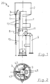
- the torch burner head 20 which consists of the upper end of a central gas channel 1, a wind apron 2 concentrically surrounding this upper end at a distance and inside the wind apron at uniform intervals around the end of the central gas channel arranged pilot burners 3.
- the upper end of the central gas channel can be configured in a suitable manner as a nozzle in order to appropriately shape the emerging flare gas stream and the resulting flame.
- a main degassing pipe 9 leading laterally outside the central channel 1 can also be seen in FIG. 1, which opens into the sleeve 11 in the radial direction.
- the sleeve 11 forms the outer wall of a double-walled hollow cylinder, which serves as a distributor 6 for degassing gas and the like.
- the inner wall of the distributor 6 is formed by a section of the central gas channel 1.
- the space between the sleeve 11 and the central channel 1 is closed in the axial direction by sealingly attached ring disks.
- three through openings are provided in the central gas channel 1 at angular intervals of 120 °, from which pipes 4 along the inner wall of the gas channel 1 guide the degassing gas emerging from the distributor 6 upward to the mouth of the central gas channel 1 .
- Fig. 1 only one of these pipes is shown as an example, while in addition the distributor opening in the central gas channel for a further pipe 4 is shown.
- the upper free end of the tubes 4 is chamfered so that the longer side of the tube Axis of the central gas channel is directed so that it is ensured that the escaping gas flows predominantly along the remaining portion of the inner wall of the gas channel 1 upwards into the flame region of the pilot burner 3.
- the free end of the tubes 4 can otherwise be used as a nozzle in any way be formed. A certain nozzle effect can also be achieved by the interaction of the outlet opening 5, which is inclined with respect to the axis of the tube 4, with a conically inwardly inclined edge of the upper end of the central gas channel.
- Fig. 1 is still a supply line 12 for one of the pilot burner 3 with lower and upper brackets 13 can be seen.
- the wind apron 2 is double-walled, which contributes to favorable malfunction conditions, since the outer wall of the wind apron 2 heats up only moderately during operation of the torch burner, so that a suction effect due to hot gases flowing up occurs especially inside the wind apron and so in draws sufficient oxygen to burn the gases as completely as possible.
- Fig. 2 it can be seen that three pilot burners 3 are arranged along the circumference of the burner head at uniform angular intervals of 120 °, each of which is assigned its own tube 4 for degassing gas, which opens immediately below the pilot burner in the same angular position.
- the upper edge of the central gas channel 1, which is not shown in Fig. 1 is slightly drawn, so that together with the oblique cut of the tubes 4 at the outlet opening, a certain nozzle effect for the under relatively low pressure escaping release gas results.
- the main degassing pipe 9 and the distributor 6 shown in dashed lines, which has outer access flaps 14 for maintenance and monitoring purposes, can also be seen in FIG. 2.
- Burnout losses are below 5% for hydrocarbons, typically in the order of 3% and below 1% for hydrogen sulfide.
Landscapes
- Engineering & Computer Science (AREA)
- Environmental & Geological Engineering (AREA)
- Mechanical Engineering (AREA)
- General Engineering & Computer Science (AREA)
- Gas Burners (AREA)
- Feeding And Controlling Fuel (AREA)
Description
- Die vorliegende Erfindung betrifft einen Fackelbrenner mit einem zentralen Gaskanal für Fackelgas, einer das obere Ende des Gaskanals im Abstand umgebenden Windschürze, innerhalb der Windschürze angeordneten Pilotbrennern und mit einer Zufuhreinrichtung in Form von Rohren für Atmungs- und Entlüftungsgas, wobei der Durchmesser der Rohre klein gegen den Durchmesser des zentralen Gaskanales ist und ihre Austrittsöffnungen auf einem Höhenniveau unterhalb der Pilotbrenner münden.
- Ein derartiger Fackelbrenner ist zum Beispiel aus der US 4,468193 bekannt.
- Der bekannte Fackelbrenner sieht mehrere Steigrohre außerhalb eines zentralen Gaskanals, jedoch innerhalb eines Hüllrohres vor. Außerhalb des Hüllrohres ist ein einzelner Pilotbrenner vorgesehen. Bei diesem bekannten Fackelbrenner sind Düsenöffnungen an den Steigrohren für das Entlösungsgas und auch die Ausströmöffnungen für das sonstige Fackelgas so vorgesehen, daß sich diese Gase möglichst gleichmäßig über den gesamten Querschnitt des Hüllrohres verteilen bevor sie durch den Fackelbrenner gezündet werden.
- Derartige Fackelbrenner werden sowohl bei der Erdöl- und Ergasförderung, als auch bei der Raffinierung und Verarbeitung von Kohlenwasserstoffprodukten verwendet. Sie dienen im Regelfall dazu, das beim Förderungs- und Produktionsprozeß anfallende und nicht verarbeitungsfähige Gas kontrolliert abzufackeln.
- Dabei wird insbesondere durch den zentralen Gaskanal auströmendes Fackelgas (Erdgas), welches relativ hochkalorig ist, verbrannt. Desweiteren fallen jedoch beim Verarbeitungs- und Produktionsprozeß auch andere niederkalorige Gase an, die zum Beispiel aus Vorratstanks abdampfen und als Atmungs- oder Entlösungsgas, oftmals auch im Hinblick auf ihre Zusammensetzung als Sauergas bezeichnet werden.
- Diese Gase bestehen hauptsächlich aus einem Gemisch aus Luft, Kohlenwasserstoffen und/oder aus Schwefelwasserstoff. Andere Gase sind nur in Spuren darin vorhanden. Diese Gemische haben keinen sehr hohen Brennwert, müssen jedoch, um eine unnötige Belastung der Umwelt zu vermeiden, ebenfalls abgefackelt werden. Aus diesem Grund sind zusätzlich zu dem zentralen Gaskanal auch weitere Zufuhreinrichtungen für derartige Atmungs- und Entlösungsgase vorgesehen.
- In der Praxis hat man hierzu im wesentlichen die zwei folgenden Wege beschritten. Gemäß einer bekannten Modifikation wird ein Entgasungsrohr außerhalb des zentralen Gaskanals nach oben in den Mündungsbereich des zentralen Gaskanals geführt und dort gegebenenfalls durch die Pilotbrenner gezündet und abgefackelt. Gemäß einer anderen bekannten Ausführungsform wird das Gas einfach in den zentralen Gaskanal geleitet und in diesem nach oben geführt, wobei sich jedoch aufgrund des niedrigen Brennwertes und des relativ großen Querschnittes des zentralen Gaskanals Entzündungsprobleme für derartiges Entlösungsgas ergeben, wobei auch sehr hohe Ausbrandverluste auftreten. Als Ausbrandverlust bezeichnet man dabei den relativen Anteil der nicht verbrannten Kohlenwasserstoffe und des Schwefelwasserstoffs im Abgas und zwar entweder bezogen auf die Gesamtabgasmenge oder aber bezogen auf den vorher im Entlösungsgas vorhandenen Kohlenwasserstoff- bzw. Schwefelwasserstoff-Anteil.
- Der möglichst vollständigen Verbrennung von Kohlenwasserstoffen in derartigen Gasen wird deshalb eine relativ große Bedeutung beigemessen, weil Kohlenwasserstoffe in sehr starkem Maße als sogenannte "Treibhausgase" wirken und den in der Öffentlichkeit bereits viel diskutierten Treibhauseffekt noch wesentlich stärker begünstigen als das mengenmäßig dominierende Kohlendioxid.
- Schwefelwasserstoff ist eine relativ giftige und unangenehm riechende Substanz, so daß diese Eigenschaften ausschlagebend dafür sind, daß auch eine möglichst vollständige Verbrennung des H₂S-Anteils angestrebt wird.
- Darüber hinaus soll außerdem das Entstehen anderer schädlicher Abgase wie Kohlenmonoxid und Stickoxide möglichst vermieden werden.
- Die bekannten Fackelbrenner haben in Bezug auf die Verbrennung von Entlösungsgas relativ hohe Ausbrandverluste, verbrennen also die brennbaren Bestandteile nur sehr unvollständig. Außerdem entstehen bei der Verbrennung relativ hohe Temperaturen, wobei auch die Bildung von Kohlenmonoxid und Stickoxiden nicht ganz ausgeschlossen ist. Die Entstehung von Schwefeldioxid ist aufgrund der Verbrennung des im Entlösungsgas enthaltenen Schwefelwasserstoffes unvermeidlich, ebenso wie die Entstehung von Kohlendioxid.
- Der vorliegenden Erfindung liegt daher die Aufgabe zugrunde, einen Fackelbrenner mit den eingangs genannten Merkmalen zu schaffen, welcher geringere Ausbrandverluste aufweist und darüber hinaus auch wenig schädliche Abgase erzeugt.
- Diese Aufgabe wird dadurch gelöst, daß Rohre innerhalb und nahe der Innenwand des zentralen Gaskanales angeordnet sind, daß ihre Zahl höchstens gleich der Zahl der Pilotbrenner ist und daß ihre Austrittsöffnungen so unterhalb der Pilotbrenner münden, daß die austretenden Entlösungsgase unmittelbar in den Bereich der Pilotbrennerflamme geführt werden.
- Diese Gestaltung des Fackelbrenners hat zur Folge, daß die schon relativ niederkalorigen Entlösungsgase ohne weitere Verdünnung unmittelbar in den Bereich der Pilotbrennerflamme geführt werden und dort schnell und weitgehend vollständig verbrennen. Es treten am Austritt der Rohre praktisch keine nennenswerten Verdünnungen der Gase mehr auf, und die brennbaren Bestandteile werden direkt einem Flammenbereich zugeführt, so daß sie auch relativ schnell zünden.
- Im Ergebnis erhält man so eine fast vollständige Verbrennung aller brennbaren Bestandteile bei relativ niedrigen Temperaturen, weil der Gasstrom in mehrere Teilgasströme aufgeteilt ist und jedem Pilotbrenner nur ein Teil des Gases zugeführt wird. Die niedrigen Temperaturen verhindern, daß Stickoxide oder Kohlenmonoxid in nennenswertem Umfang im Abgas entstehen.
- Gemäß einer bevorzugten Ausführungsform der Erfindung sind die Austrittsöffnungen der Rohre durch einen Schnitt entlang einer zur Rohrachse geneigten Ebene gebildet. Es sind also keine speziellen Düsen erforderlich, welche den aus den Rohren austretenden Gasstrom lenken. Wenn die Ebene der Austrittsöffnungen schräg zur Rohrachse liegt, ist es zweckmäßig und vorteilhaft, diese teilweise auch seitlich von der Rohrachse weg gerichteten Austrittsöffnungen zur Innenwand des Gaskanales hin zu richten. Das Gas streicht dann entlang des verbleibenden Teiles der Innenwand nach oben unmittelbar vor die Mündung des Pilotbrenners, der ebenfalls in diesem Bereich mündet. Dabei ist der Abstand der Austrittsöffnung eines solchen Rohres zur Austrittsöffnung des zentralen Gaskanales relativ gering. Auch der Durchmesser der Rohre für das Entlösungsgas ist relativ klein gegenüber dem Durchmesser des zentralen Gaskanals. Zweckmäßigerweise werden alle Rohre als zylindrische Rohre ausgebildet. Die Windschürze ist im wesentlichen ein einfacher oder auch doppelwandiger Zylindermantel, der den oberen Bereich des zentralen Gaskanals im Abstand umgibt. Eine derartige Windschürze sorgt für günstige Strömungsverhältnisse an der Austrittsöffnung des zentralen Gaskanals und dient gleichzeitig als Sichtblende, so daß das Abfackeln von Entlösungsgas und die Flammen der Pilotbrenner von außerhalb im allgemeinen nicht zu sehen sind.
- Die Pilotbrenner sind dabei im Zwischenraum zwischen der Windschürze und dem oberen Ende des zentralen Gaskanals angeordnet und mit ihrer Mündung zur Achse des zentralen Gaskanals hin gerichtet.
- Die Austrittsöffnungen der Rohre für das Entlösungsgas münden vorzugsweise relativ dicht unterhalb des oberen Endes des zentralen Gaskanals und damit auch unmittelbar unter den Mündungen der Pilotbrenner. Die Pilotbrenner sind in gleichmäßigen Abständen entlang des Umfanges des zentralen Gaskanals verteilt, z. B. drei Pilotbrenner in Winkelabständen von 120°. Jedem dieser Pilotbrenner ist vorzugsweise ein Rohr für Entlösungsgas zugeordnet, welches die gleiche Winkelposition wie der zugehörige Pilotbrenner hat und an der Innenwand des zentralen Gaskanals nach oben geführt ist. Das Entlösungsgas wird somit direkt und unverdünnt in den Flammenbereich des Pilotbrenners geführt.
- Zweckmäßigerweise ist gemäß einer bevorzugten Ausführungsform der Erfindung vorgesehen, daß der Verteiler ein Doppelzylinder ist, in dessen Zwischenraum axial oder radial von außen mindestens ein Hauptentgasungsrohr mündet, während von der zylindrischen Innenwand des Verteilers aus die einzelnen Rohre für das Entlösungsgas abzweigen. Zweckmäßigerweise wird dabei der Verteiler derart gestattet, daß im Abstand von dem oberen Ende des zentralen Gaskanals eine Manschette den zentralen Gaskanal im Abstand konzentrisch umgibt, so daß zwischen der Innenwand der Manschette und der Außenwand des zentralen Gaskanals ein ringförmniger Zwischenraum gebildet wird. In axialer Richtung wird dieser Zwischenraum durch passende flache Ringe verschlossen.
- In radialer Richtung weist die Manschette eine Anschlußöffnung für den Anschluß eines Hauptentgasungsrohres für Entlösungsgas auf. Der zentrale Gaskanal weist dann im Bereich der Manschette, vorzugsweise in gleichen Winkelabständen Austriffsöffnungen für das Entlösungsgas auf, an welcher die bereits erwähnten Rohre angeschlossen sind, die dann das Entlösungsgas den ihnen zugeordneten Pilotbrennern zuführen.
Das Hauptentgasungsrohr könnte jedoch auch im Bereich des unteren Ringes axial in einen derartigen Verteilerraum geführt werden. Zusätzlich kann die Manschette auch eine Öffnungsklappe für Kontrollzwecke aufweisen. - Besonders bevorzugt ist eine Ausführungsform der Erfindung, bei welcher die Achse eines Pilotbrenners und die Achse des zugehörigen Rohres auf einen gemeinsamen Punkt vor der Austrittsöffnung des Pilotbrenners und vor der Austrittsöffnung des Rohres konvergieren. Dieser Punkt liegt vorzugsweise im Flammenkern des Pilotbrenners.
- Weitere Vorteile, Merkmale und Anwendungsmöglichkeiten der vorliegenden Erfindung werden deutlich anhand der folgenden Beschreibung einer bevorzugten Ausführungsform und der dazugehörigen Figuren. Es zeigen:
- Fig. 1
- einen Längsschnitt durch den oberen Teil eines Fackelbrenners und
- Fig. 2
- eine Draufsicht auf den Fackelbrennerkopf.
- In Fig. 1 erkennt man den Fackelbrennerkopf 20, der aus dem oberen Ende eines zentralen Gaskanals 1, einer dieses obere Ende im Abstand konzentrisch umgebenden Windschürze 2 und im Innern der Windschürze in gleichmäßigen Abständen um das Ende des zentralen Gaskanals herum angeordneten Pilotbrennern 3 besteht. Das obere Ende des zentralen Gaskanals kann in geeigneter Weise als Düse ausgestaltet werden, um den austretenden Fackelgasstrom und die entstehende Flamme in geeigneter Weise zu formen.
- Außer dem Brennerkopf 20 erkennt man in Fig. 1 auch noch ein seitlich außerhalb des zentralen Kanals 1 aufwärts führendes Hauptentgasungsrohr 9, welches in radialer Richtung in die Manschette 11 mündet.
- Die Manschette 11 bildet die Außenwand eines doppelwandigen Hohlzylinders, der als Verteiler 6 für Entlösungsgas und dergleichen dient. Die Innenwand des Verteilers 6 wird durch einen Abschnitt des zentralen Gaskanals 1 gebildet. Der Zwischenraum zwischen der Manschette 11 und dem zentralen Kanal 1 wird in axialer Richtung durch dichtend angebrachte Ringscheiben verschlossen. Im oberen Bereich des Verteilers 6 sind innen unter Winkelabständen von jeweils 120° drei Durchgangsöffnungen im zentralen Gaskanal 1 vorgesehen, von welchen aus Rohre 4 entlang der Innenwand des Gaskanals 1 das aus dem Verteiler 6 austretende Entlösungsgas nach oben an die Mündung des zentralen Gaskanals 1 leiten. In Fig. 1 ist nur eines dieser Rohre beispielhaft dargestellt, während zusätzlich die Verteileröffnung im zentralen Gaskanal für ein weiteres Rohr 4 dargestellt ist.
- Das obere freie Ende der Rohre 4 ist derart abgeschrägt, daß die längere Seite des Rohres zur Achse des zentralen Gaskanals hin gerichtet ist, so daß sichergestellt wird, daß das austretende Gas vorwiegend entlang des verbleibenden Abschnittes der Innenwand des Gaskanals 1 nach oben in den Flammenbereich des Pilotbrenners 3 strömt Das freie Ende der Rohre 4 kann im übrigen in beliebiger Weise als Düse ausgebildet werden. Eine gewisse Düsenwirkung läßt sich auch durch Zusammenwirken der bezüglich der Achse des Rohres 4 schräg verlaufenden Austrittsöffnung 5 mit einem konisch einwärts geneigten Rand des oberen Endes des zentralen Gaskanals erzielen.
- In den vorliegenden Skizzen sind alle Teile im wesentlichen nur schematisch dargestellt, und es versteht sich, daß die detaillierte strömungsgünstige Ausgestaltung aller Komponenten entsprechend dem Wissen des einschlägig vorgebildeten Fachmannes vorgenommen werden kann.
- In Fig. 1 ist weiterhin noch eine Zufuhrleitung 12 für einen der Pilotbrenner 3 mit unteren und oberen Halterungen 13 zu erkennen. In der dargestellten Ausführungsform ist die Windschürze 2 doppelwandig, was zu günstigen Störmungsverhältnissen beiträgt, da sich die äußere Wand der Windschürze 2 im Betrieb des Fackelbrenners nur mäßig erwärmt, so daß ein Saugeffekt durch aufströmende heiße Gase vor allem im Innern der Windschürze auftritt und so in ausreichendem Maße Sauerstoff zur möglichst vollständigen Verbrennung der Gase nachzieht.
- In Fig. 2 erkennt man, daß entlang des Umfangs des Brennerkopfes in gleichmäßigen Winkelabständen von 120° drei Pilotbrenner 3 angeordnet sind, denen jeweils ein eigenes Rohr 4 für Entlösungsgas zugeordnet ist, weiches unmittelbar unterhalb des Pilotbrenners in der gleichen Winkelposition mündet. In Fig. 2 erkennt man, daß der obere Rand des zentralen Gaskanales 1, was in Fig. 1 nicht dargestellt ist, etwas eingezogen ist, so daß sich zusammen mit dem schrägen Anschnitt der Rohre 4 an der Austrittsöffnung ein gewisser Düseneffekt für das unter relativ niedrigem Druck ausströmende Entlösungsgas ergibt. Man erkennt weiterhin in Fig. 2 noch das Hauptentgasungsrohr 9 und den gestrichelt eingezeichneten Verteiler 6, der äußere Zugangsklappen 14 zu Wartungs- und Überwachungszwecken hat.
- Mit einem so gestalteten Fackelbrenner erreicht man auch für die niederkalorigen Entlösungsgase eine fast vollständige Verbrennung von Kohlenwasserstoffen und Schwefelwasserstoff mit einem niedrigen Gehalt von Schadstoffen im Abgas.
- Die Ausbrandverluste liegen für Kohlenwasserstoffe unterhalb von 5 %, typischerweise in der Größenordnunt von 3 % und für Schwefelwasserstoff unter 1 %.
-
- 1
- Gaskanal
- 2
- Windschürze
- 3
- Pilotbrenner
- 4
- Rohre
- 5
- Austrittsöffnung
- 6
- Verteiler
- 9
- Hauptentgasungsrohr
- 11
- Manschette
- 1
- 2 Zufuhrleitung
- 13
- Halterungen
- 14
- Zugangsklappen
- 20
- Fackelbrennerkopf
Claims (7)
- Fackelbrenner mit einem zentralen Gaskanal (1) für Fackelgas, einer das obere Ende des Gaskanals (1) im Abstand umgebenden Windschürze (2), innerhalb der Windschürze angeordneten Pilotbrennern (3) und mit einer Zufuhreinrichtung in Form von Rohren (4) für Atmungs- und Entlüftungsgas, wobei der Durchmesser der Rohre (4) klein gegen den Durchmesser des zentralen Gaskanales (1) ist und ihre Austrittsöffnungen auf einem Höhenniveau unterhalb der Pilotbrenner (3) münden, dadurch gekennzeichnet, daß die Rohre (4) innerhalb und nahe der Innenwand des zentralen Gaskanales (1) angeordnet sind, daß ihre Zahl höchstens gleich der Zahl der Pilotbrenner (3) ist und daß ihre Austrittsöffnungen so unterhalb der Pilotbrenner (3) münden, daß die austretenden Entlösungsgase unmittelbar in den Bereich der Pilotbrennerflamme geführt werden.
- Fackelbrenner nach Anspruch 1, dadurch gekennzeichnet, daß die Austrittsöffnungen (5) der Rohre (4) durch einen Schnitt entlang einer zur Rohrachse geneigten Ebene gebildet sind.
- Fackelbrenner nach Anspruch 2, dadurch gekennzeichnet, daß die Austrittsöffnungen (5) der Rohre (4) teilweise zur Wand des Zentralkanals (1) gerichtet sind.
- Fackelbrenner nach einem der Ansprüche 1 bis 3, dadurch gekennzeichnet, daß die Austrittsöffnungen (5) der Rohre (4) im Bereich der Austrittsöffnung des Zentralkanals (1) münden.
- Fackelbrenner nach einem der Ansprüche 1 bis 3, dadurch gekennzeichnet, daß im Abstand zu den Austrittsöffnungen (5) am zentralen Gaskanal (1) ein Verteiler (6) für die Verteilung von Gas zu den einzelnen Rohren (4) von einer Hauptentgasungsleitung (9) aus vorgesehen ist.
- Fackelbrenner nach Anspruch 5, dadurch gekennzeichnet, daß der Verteiler (6) ein Doppelzylinder ist, in dessen Zwischenraum (8) axial oder radial von außen mindestens ein Hauptentgasungsrohr (9) mündet, während die Rohre (4) der Zufuhreinrichtung von der zylindrischen Innenwand (10) des Verteilers (6) ausgehend entlang der Innenwand des zentralen Gaskanales (1) nach oben verlaufen.
- Fackelbrenner nach einem der Ansprüche 1 bis 6, dadurch gekennzeichnet, daß die Achse der Pilotbrenner (3) und die Achse der den Pilotbrennern zugeordneten Rohre (4) auf einen Punkt vor der Austrittsöffnung des Pilotbrenners und vor der Austrittsöffnung (5) der Rohre (4) konvergieren.
Applications Claiming Priority (2)
| Application Number | Priority Date | Filing Date | Title |
|---|---|---|---|
| DE4029715A DE4029715A1 (de) | 1990-09-19 | 1990-09-19 | Fackelbrenner |
| DE4029715 | 1990-09-19 |
Publications (3)
| Publication Number | Publication Date |
|---|---|
| EP0476548A2 EP0476548A2 (de) | 1992-03-25 |
| EP0476548A3 EP0476548A3 (en) | 1992-09-02 |
| EP0476548B1 true EP0476548B1 (de) | 1995-03-08 |
Family
ID=6414561
Family Applications (1)
| Application Number | Title | Priority Date | Filing Date |
|---|---|---|---|
| EP91115607A Expired - Lifetime EP0476548B1 (de) | 1990-09-19 | 1991-09-14 | Fackelbrenner |
Country Status (3)
| Country | Link |
|---|---|
| EP (1) | EP0476548B1 (de) |
| AT (1) | ATE119651T1 (de) |
| DE (2) | DE4029715A1 (de) |
Families Citing this family (5)
| Publication number | Priority date | Publication date | Assignee | Title |
|---|---|---|---|---|
| DE19854581A1 (de) * | 1998-11-26 | 2000-06-08 | Messer Griesheim Gmbh | Vorrichtung und Verfahren zum Umwandeln des Boil-Off-Gases von Kryo-Kraftstofftanks |
| US6702572B2 (en) | 2001-08-20 | 2004-03-09 | John Zink Company, Llc | Ultra-stable flare pilot and methods |
| CN105927992A (zh) * | 2016-04-21 | 2016-09-07 | 北京航天动力研究所 | 一种可处理有毒气体的空气预混型火炬燃烧器 |
| CN114110625A (zh) * | 2021-09-26 | 2022-03-01 | 南高齿(包头)传动设备有限公司 | 废气燃烧装置 |
| CN114278961A (zh) * | 2021-12-14 | 2022-04-05 | 陕西航空电气有限责任公司 | 一种稳焰节能高效的多功能长明灯 |
Family Cites Families (2)
| Publication number | Priority date | Publication date | Assignee | Title |
|---|---|---|---|---|
| US3429645A (en) * | 1967-09-20 | 1969-02-25 | Zink Co John | Flare stack burner |
| US4468193A (en) * | 1983-03-03 | 1984-08-28 | Mcgill Incorporated | Staged hydrocarbon combustion system |
-
1990
- 1990-09-19 DE DE4029715A patent/DE4029715A1/de not_active Withdrawn
-
1991
- 1991-09-14 DE DE59104859T patent/DE59104859D1/de not_active Expired - Fee Related
- 1991-09-14 AT AT91115607T patent/ATE119651T1/de not_active IP Right Cessation
- 1991-09-14 EP EP91115607A patent/EP0476548B1/de not_active Expired - Lifetime
Also Published As
| Publication number | Publication date |
|---|---|
| EP0476548A3 (en) | 1992-09-02 |
| EP0476548A2 (de) | 1992-03-25 |
| DE59104859D1 (de) | 1995-04-13 |
| DE4029715A1 (de) | 1992-03-26 |
| ATE119651T1 (de) | 1995-03-15 |
Similar Documents
| Publication | Publication Date | Title |
|---|---|---|
| DE69130927T2 (de) | Verbrennungsvorrichtung | |
| DE2731562C2 (de) | Brenner für flüssige und/oder gasförmige Brennstoffe | |
| EP0111874B1 (de) | Einrichtung zum Verbrennen insbesondere von reaktionsträgem Kohlenstaub | |
| EP0756134B1 (de) | Verfahren und Brenner zur Verminderung der Bildung von NOx bei der Verbrennung von Kohlenstaub | |
| DE69821730T2 (de) | Brennstoffzerstäubungsbrenner und Verbrennungsverfahren durchgeführt mit diesem Brenner | |
| DE2421452B2 (de) | Vorrichtung zum Verfeuern von Kohlenstaub | |
| DE3933050C2 (de) | Verfahren zum Betreiben eines Brenners für Drehrohröfen und Brenner hierfür | |
| DE69212686T2 (de) | Brenneranlage für fliessfähige Abfallstoffe | |
| DE3842842A1 (de) | Atmosphaerischer brenner | |
| DE3200395A1 (de) | Bodenfackelrohr | |
| DE1937922B2 (de) | Abgasfackelbrenner | |
| WO2007101427A1 (de) | Rundbrenner | |
| DE3011631C2 (de) | Verfahren zum Betrieb einer Kohlenstaub-Kesselfeuerung und für das Verfahren eingerichtete Kohlenstaub-Kesselfeuerung | |
| DE1476817A1 (de) | Vorrichtung zur Einleitung von Waerme in die Austrittsgase einer Gasturbine | |
| DE1992618U (de) | Gasbrenner. | |
| DE2604090A1 (de) | Mit rauchunterdrueckung und unsichtbarer flamme arbeitender brenner an fackelkaminen | |
| EP0476548B1 (de) | Fackelbrenner | |
| DE69919456T2 (de) | Brenner mit konzentrischer Luftzufuhr und zentral angeordnetem Stabilisator | |
| DE2934787A1 (de) | Wirbelbrettbrennkammer | |
| DE1083001B (de) | Verfahren und Vorrichtung zur Herstellung von Aktivruss | |
| DE4008692A1 (de) | Mischeinrichtung fuer oelgeblaesebrenner | |
| DE1936785A1 (de) | Vorrichtung und Verfahren zur Reinigung von Luft | |
| DE4446609A1 (de) | Verfahren und Vorrichtung zur Brennstoffzuführung zu einem sowohl für flüssige als auch für gasförmige Brennstoffe geeigneten Brenner | |
| EP0703413B1 (de) | Brennkammer einer Gasturbogruppe | |
| DE1751154A1 (de) | Brenner |
Legal Events
| Date | Code | Title | Description |
|---|---|---|---|
| PUAI | Public reference made under article 153(3) epc to a published international application that has entered the european phase |
Free format text: ORIGINAL CODE: 0009012 |
|
| AK | Designated contracting states |
Kind code of ref document: A2 Designated state(s): AT BE CH DE DK ES FR GB GR IT LI LU NL SE |
|
| PUAL | Search report despatched |
Free format text: ORIGINAL CODE: 0009013 |
|
| AK | Designated contracting states |
Kind code of ref document: A3 Designated state(s): AT BE CH DE DK ES FR GB GR IT LI LU NL SE |
|
| 17P | Request for examination filed |
Effective date: 19921030 |
|
| 17Q | First examination report despatched |
Effective date: 19930316 |
|
| GRAA | (expected) grant |
Free format text: ORIGINAL CODE: 0009210 |
|
| AK | Designated contracting states |
Kind code of ref document: B1 Designated state(s): AT BE CH DE DK ES FR GB GR IT LI LU NL SE |
|
| PG25 | Lapsed in a contracting state [announced via postgrant information from national office to epo] |
Ref country code: IT Free format text: LAPSE BECAUSE OF FAILURE TO SUBMIT A TRANSLATION OF THE DESCRIPTION OR TO PAY THE FEE WITHIN THE PRE;WARNING: LAPSES OF ITALIAN PATENTS WITH EFFECTIVE DATE BEFORE 2007 MAY HAVE OCCURRED AT ANY TIME BEFORE 2007. THE CORRECT EFFECTIVE DATE MAY BE DIFFERENT FROM THE ONE RECORDED.SCRIBED TIME-LIMIT Effective date: 19950308 Ref country code: BE Effective date: 19950308 Ref country code: GR Free format text: LAPSE BECAUSE OF FAILURE TO SUBMIT A TRANSLATION OF THE DESCRIPTION OR TO PAY THE FEE WITHIN THE PRESCRIBED TIME-LIMIT Effective date: 19950308 Ref country code: DK Effective date: 19950308 Ref country code: NL Free format text: LAPSE BECAUSE OF NON-PAYMENT OF DUE FEES Effective date: 19950308 Ref country code: ES Free format text: THE PATENT HAS BEEN ANNULLED BY A DECISION OF A NATIONAL AUTHORITY Effective date: 19950308 |
|
| REF | Corresponds to: |
Ref document number: 119651 Country of ref document: AT Date of ref document: 19950315 Kind code of ref document: T |
|
| REF | Corresponds to: |
Ref document number: 59104859 Country of ref document: DE Date of ref document: 19950413 |
|
| GBT | Gb: translation of ep patent filed (gb section 77(6)(a)/1977) |
Effective date: 19950330 |
|
| ET | Fr: translation filed | ||
| PG25 | Lapsed in a contracting state [announced via postgrant information from national office to epo] |
Ref country code: SE Effective date: 19950608 |
|
| NLV1 | Nl: lapsed or annulled due to failure to fulfill the requirements of art. 29p and 29m of the patents act | ||
| PG25 | Lapsed in a contracting state [announced via postgrant information from national office to epo] |
Ref country code: CH Effective date: 19950930 Ref country code: LU Free format text: LAPSE BECAUSE OF NON-PAYMENT OF DUE FEES Effective date: 19950930 Ref country code: LI Effective date: 19950930 |
|
| PLBE | No opposition filed within time limit |
Free format text: ORIGINAL CODE: 0009261 |
|
| STAA | Information on the status of an ep patent application or granted ep patent |
Free format text: STATUS: NO OPPOSITION FILED WITHIN TIME LIMIT |
|
| 26N | No opposition filed | ||
| REG | Reference to a national code |
Ref country code: CH Ref legal event code: PL |
|
| PGFP | Annual fee paid to national office [announced via postgrant information from national office to epo] |
Ref country code: FR Payment date: 19980923 Year of fee payment: 8 Ref country code: GB Payment date: 19980923 Year of fee payment: 8 |
|
| PGFP | Annual fee paid to national office [announced via postgrant information from national office to epo] |
Ref country code: AT Payment date: 19980929 Year of fee payment: 8 |
|
| PGFP | Annual fee paid to national office [announced via postgrant information from national office to epo] |
Ref country code: DE Payment date: 19981022 Year of fee payment: 8 |
|
| PG25 | Lapsed in a contracting state [announced via postgrant information from national office to epo] |
Ref country code: AT Free format text: LAPSE BECAUSE OF NON-PAYMENT OF DUE FEES Effective date: 19990914 Ref country code: GB Free format text: LAPSE BECAUSE OF NON-PAYMENT OF DUE FEES Effective date: 19990914 |
|
| GBPC | Gb: european patent ceased through non-payment of renewal fee |
Effective date: 19990914 |
|
| PG25 | Lapsed in a contracting state [announced via postgrant information from national office to epo] |
Ref country code: FR Free format text: LAPSE BECAUSE OF NON-PAYMENT OF DUE FEES Effective date: 20000531 |
|
| PG25 | Lapsed in a contracting state [announced via postgrant information from national office to epo] |
Ref country code: DE Free format text: LAPSE BECAUSE OF NON-PAYMENT OF DUE FEES Effective date: 20000701 |
|
| REG | Reference to a national code |
Ref country code: FR Ref legal event code: ST |