EP0475585A1 - Verfahren und Einrichtung zur Glättung des Aufwärtsschaltvorganges in einem automatischen Getriebe - Google Patents
Verfahren und Einrichtung zur Glättung des Aufwärtsschaltvorganges in einem automatischen Getriebe Download PDFInfo
- Publication number
- EP0475585A1 EP0475585A1 EP91307344A EP91307344A EP0475585A1 EP 0475585 A1 EP0475585 A1 EP 0475585A1 EP 91307344 A EP91307344 A EP 91307344A EP 91307344 A EP91307344 A EP 91307344A EP 0475585 A1 EP0475585 A1 EP 0475585A1
- Authority
- EP
- European Patent Office
- Prior art keywords
- torque
- shift
- phase
- speed
- fluid pressure
- Prior art date
- Legal status (The legal status is an assumption and is not a legal conclusion. Google has not performed a legal analysis and makes no representation as to the accuracy of the status listed.)
- Granted
Links
Images


Classifications
-
- F—MECHANICAL ENGINEERING; LIGHTING; HEATING; WEAPONS; BLASTING
- F16—ENGINEERING ELEMENTS AND UNITS; GENERAL MEASURES FOR PRODUCING AND MAINTAINING EFFECTIVE FUNCTIONING OF MACHINES OR INSTALLATIONS; THERMAL INSULATION IN GENERAL
- F16H—GEARING
- F16H63/00—Control outputs from the control unit to change-speed- or reversing-gearings for conveying rotary motion or to other devices than the final output mechanism
- F16H63/40—Control outputs from the control unit to change-speed- or reversing-gearings for conveying rotary motion or to other devices than the final output mechanism comprising signals other than signals for actuating the final output mechanisms
- F16H63/50—Signals to an engine or motor
- F16H63/502—Signals to an engine or motor for smoothing gear shifts
-
- F—MECHANICAL ENGINEERING; LIGHTING; HEATING; WEAPONS; BLASTING
- F16—ENGINEERING ELEMENTS AND UNITS; GENERAL MEASURES FOR PRODUCING AND MAINTAINING EFFECTIVE FUNCTIONING OF MACHINES OR INSTALLATIONS; THERMAL INSULATION IN GENERAL
- F16H—GEARING
- F16H61/00—Control functions within control units of change-speed- or reversing-gearings for conveying rotary motion ; Control of exclusively fluid gearing, friction gearing, gearings with endless flexible members or other particular types of gearing
- F16H61/04—Smoothing ratio shift
- F16H61/06—Smoothing ratio shift by controlling rate of change of fluid pressure
- F16H61/061—Smoothing ratio shift by controlling rate of change of fluid pressure using electric control means
-
- B—PERFORMING OPERATIONS; TRANSPORTING
- B60—VEHICLES IN GENERAL
- B60W—CONJOINT CONTROL OF VEHICLE SUB-UNITS OF DIFFERENT TYPE OR DIFFERENT FUNCTION; CONTROL SYSTEMS SPECIALLY ADAPTED FOR HYBRID VEHICLES; ROAD VEHICLE DRIVE CONTROL SYSTEMS FOR PURPOSES NOT RELATED TO THE CONTROL OF A PARTICULAR SUB-UNIT
- B60W2510/00—Input parameters relating to a particular sub-units
- B60W2510/10—Change speed gearings
- B60W2510/1015—Input shaft speed, e.g. turbine speed
-
- F—MECHANICAL ENGINEERING; LIGHTING; HEATING; WEAPONS; BLASTING
- F16—ENGINEERING ELEMENTS AND UNITS; GENERAL MEASURES FOR PRODUCING AND MAINTAINING EFFECTIVE FUNCTIONING OF MACHINES OR INSTALLATIONS; THERMAL INSULATION IN GENERAL
- F16H—GEARING
- F16H59/00—Control inputs to control units of change-speed-, or reversing-gearings for conveying rotary motion
- F16H59/36—Inputs being a function of speed
- F16H59/38—Inputs being a function of speed of gearing elements
- F16H2059/385—Turbine speed
-
- F—MECHANICAL ENGINEERING; LIGHTING; HEATING; WEAPONS; BLASTING
- F16—ENGINEERING ELEMENTS AND UNITS; GENERAL MEASURES FOR PRODUCING AND MAINTAINING EFFECTIVE FUNCTIONING OF MACHINES OR INSTALLATIONS; THERMAL INSULATION IN GENERAL
- F16H—GEARING
- F16H59/00—Control inputs to control units of change-speed-, or reversing-gearings for conveying rotary motion
- F16H59/36—Inputs being a function of speed
- F16H59/38—Inputs being a function of speed of gearing elements
- F16H59/42—Input shaft speed
- F16H2059/425—Rate of change of input or turbine shaft speed
-
- F—MECHANICAL ENGINEERING; LIGHTING; HEATING; WEAPONS; BLASTING
- F16—ENGINEERING ELEMENTS AND UNITS; GENERAL MEASURES FOR PRODUCING AND MAINTAINING EFFECTIVE FUNCTIONING OF MACHINES OR INSTALLATIONS; THERMAL INSULATION IN GENERAL
- F16H—GEARING
- F16H61/00—Control functions within control units of change-speed- or reversing-gearings for conveying rotary motion ; Control of exclusively fluid gearing, friction gearing, gearings with endless flexible members or other particular types of gearing
- F16H2061/0075—Control functions within control units of change-speed- or reversing-gearings for conveying rotary motion ; Control of exclusively fluid gearing, friction gearing, gearings with endless flexible members or other particular types of gearing characterised by a particular control method
- F16H2061/0087—Adaptive control, e.g. the control parameters adapted by learning
Definitions
- This invention relates to methods and systems for controlling automatic transmissions and, in particular, to methods and systems for electrically controlling automatic transmissions to improve smoothness of upshifts.
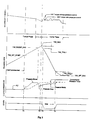
- Two phases typically occur during an upshift of an automatic transmission of an automatic vehicle drive line, namely, a torque phase and an inertia phase.
- the torque input to the transmission clutches includes only the engine combustion torque passing through a torque converter.
- pressure is applied to the incoming clutch element.
- the input torque is split between the outgoing clutch and the incoming clutch.
- the torque carried by the outgoing clutch drops to zero and all the torque is carried by the incoming clutch element.
- the output torque is reduced because of the change in gear ratio.
- the ratio transfer phase or the inertia phase begins.
- the engine speed is reduced rapidly to the level of the new gear ratio.
- This inertia torque creates a torque bump which is transmitted to the passenger compartment.
- the magnitude of the torque bump is dependent on the clutch pressure at the start of the inertia phase.
- One method of reducing the inertia bump is to reduce the pressure to the clutch during the shift. However, this lengthens the shift time (torque phase and the inertia phase) and, consequently, the shift feels dragged out. Also, a large amount of heat is created which has to be absorbed by the clutches.
- U.S. patents disclose shift shock minimizing systems which control the line pressure supplied to the on-coming transmission friction element.
- the U.S. patent to Ishimaru et al., No. 3,855,880 discloses a system which reduces line pressure to the on-coming transmission friction element just prior to engagement of that element in order to provide a smooth coupling.
- U.S. Patent No. 4,845,618 issued to Narita discloses a system for controlling clutch pressure during a shift.
- the clutch pressure is maintained at a stored target value that is called out as a result of the monitoring of turbine torque.
- the line pressure supplied to the oncoming clutch is determined based on sensed engine output and torque converter output speeds.
- a number of U.S. patents disclose control systems for minimizing shocks during shifting operations in transmissions wherein the engine spark timing is adjusted in order to reduce output torque during the shifts.
- the engine spark timing is employed to reduce output torque during shifting.
- the supply pressure to the oncoming transmission friction element during the shift is dependent upon a sensed ratio of input-to-output speed of the transmission.
- the ′988 patent further describes a closed loop control for a clutch during a shift using a continuous monitoring of speed ratio across the clutch.
- the ignition timing is retarded to reduce output engine torque after a specified time delay from the occurrence of a shift command and prior to unlocking of the torque converter.
- An object of the present invention is to provide a method and system for improving smoothness of upshifts in an automatic transmission wherein the shifting includes a torque phase and an inertia phase and wherein control of the shift is provided by continuously monitoring turbine speed and comparing a turbine speed change at the end of the torque phase with a stored value.
- the control is augmented by retarding engine spark for a controlled time.
- Another object of the present invention is to provide a method and system for improving smoothness of upshifting in an automatic transmission wherein the shifting includes a torque phase and an inertia phase and wherein line pressure to an oncoming transmission clutch of the transmission is (1) boosted during the initial torque phase of the shift, (2) then quickly reduced, and (3) ramped during the inertia phase and wherein engine spark timing is retarded during the shifting operation.
- an automotive vehicle driveline comprising a multiple speed ratio automatic transmission having a frictional element associated with a specified speed ratio, an internal combustion engine, a torque input shaft for coupling the engine and the transmission, and a fluid pressure control system including fluid pressure generating means for generating a fluid pressure
- a method for increasing shift smoothness when shifting from a currently engaged speed ratio to the specified speed ratio.
- the shifting including a torque phase and an inertia phase.
- the control system further includes control means for controlling the fluid pressure generating means such that the level of the fluid pressure generated by the fluid pressure generating means is supplied to the frictional element during the torque and inertia phases in accordance with a pressure schedule to initiate and progressively increase the torque transmission therethrough.
- the method includes the steps of generating a speed signal based on the instantaneous speed of the input shaft during the torque and inertia phases and generating a shift signal to indicate the desired shift from the currently engaged speed ratio to the specified speed ratio.
- the value of the speed signal changes during the torque and inertia phases.
- the method further includes the steps of correlating the shift signal to the pressure schedule so that the level of fluid pressure controlled by the control means increases at the start of the torque phase to quickly complete the torque phase and correlating the speed signal to the pressure schedule so that the level of fluid pressure controlled by the control means decreases immediately before the completion of the torque phase to reduce the torque bump in the inertia stage.
- a system is also provided for carrying out the above method steps.
- an adaptive control system for regulating pressure in a friction torque establishing device for an automotive vehicle driveline having an internal combustion engine and multiple ratio transmission gearing.
- the system includes a torque input shaft between the engine and the gearing, a first friction mechanism adapted to establish in part a first torque flow path between the input shaft and first torque input gear elements of said gearing and a second friction mechanism adapted to establish in part a second torque flow path between the input shaft and second torque input gear elements.
- the system further includes first and second pressure operated servos adapted when pressurized to energize the first and second friction mechanisms, respectively, the establishment of the second torque flow path being accompanied by a decreased engine speed, means for continuously monitoring the speed of the torque input shaft and means for increasing the pressure of the second servo upon a command of a shift in gearing ratio that requires release of the first friction mechanism and application of the second friction mechanism.
- the system includes means for decreasing the servo pressure in response to a predetermined detected change in torque input shaft speed and means for increasing the servo pressure following a decrease in the clutching capacity of the first friction mechanism during the ratio shift.
- the method and system also include the feature of retarding engine spark for a controlled time during the inertia phase to further improve shift quality.
- FIG. 1 a power train controller or microprocessor 10 which controls a vehicle engine 12 30 and a transmission 14 coupled thereto.
- the controller 10 receives input signals from various sensors which measure engine, transmission and other vehicle operating conditions. Details of the system of Figure 1 are more fully disclosed in co-pending patent application Serial 35 No. 383,506, filed July 24, 1989 and entitled "Electronic Control System For Controlling Torque Converter Bypass Clutches". This application has the same assignee as the present invention and is hereby incorporated by reference in its entirety.
- One output of the controller 10 is transferred to a bypass clutch pulse width modulated solenoid.
- the solenoid valve controlled by the pulse width modulated solenoid modulates the pressure in a solenoid feed pressure passage and delivers a control signal to the bypass clutch control valve.
- the clutch control valve is calibrated to receive the control pressure of the solenoid output to establish in a control chamber a pressure that will determine the controlled slip of the bypass clutch which couples engine torque to the transmission 14.
- Figure 2 of the co-pending application noted above shows in schematic form the architecture of the controller 10 as well as the relationship of the controller 10 to the hydraulic control valve body and to the transmission clutches and brakes.
- Figure 2 also shows the schematic arrangement of the various sensors with respect to the processor and the hydraulic control valve body.
- the sensors convert physical signals to electrical signals.
- Physical signals include throttle position or engine manifold pressure (i.e. air charge), engine speed (transmission turbine speed), and transmission gear ratio selection as well as other variables such as transmission oil temperature, vehicle speed and the vehicle brake condition.
- the controller 10 inputs these signals and operates on them according to a control program or a strategy as discussed below and then outputs the results to certain actuators which function in cooperation with the hydraulic valve body to control the transmission 14.
- the controller 10 includes a central processing unit or CPU which comprises a computation unit and a control unit.
- An internal control bus establishes a relationship between memory unit and the processing unit.
- Other internal busses establish a relationship between the CPU and an input conditioning signal circuit and an output driver circuit.
- the CPU executes programs that are fetched from memory and provide the timing and controlled values of the output signals to the hydraulic control valve body of the transmission.
- the input signal conditioning and the output driver system allow the controller 10 to read and write data under program control.
- the memory portion of the controller 10 stores programs and data and provides data to the controller 10 as well as accepting new data from the CPU for storage.
- the memory portion of the controller 10 of Figure 1 includes two types of memory; first, a read only memory or ROM which stores information or data that is read by the processor in each background loop and, second, a random access memory or RAM which holds or temporarily stores the results of the computations of the CPU as well as other data.
- the contents of the RAM can be erased, rewritten or changed depending upon the operating conditions of the vehicle.
- the two types of memory are located in an integrated circuit in the form of a microprocessor chip whereas the computations performed by the CPU are the result of the function of a second integrated circuit comprising a separate microprocessor chip, the two chips being connected by an internal bus and interface circuitry.
- One of the input signals to the controller 10 is a throttle position signal along a line which is generated by a position sensor.
- An engine speed sensor preferably in the form of a profile and condition pickup (PIP)
- PIP profile and condition pickup
- a transmission oil sensor delivers an oil temperature signal along a line to the controller 10.
- a barometric pressure sensor also delivers an altitude signal to the controller 10.
- a vehicle speed sensor measures or senses the speed of the driven element of the transmission 11 which is an indicator of the vehicle speed. That signal is delivered through a line to the controller 10.
- the drive range for the transmission 14 is selected by the vehicle operator by manual adjustment of an adjustment lever.
- the various ranges are reverse, neutral, drive (D), direct drive ratios (3) and low speed ratio (1).
- Various shift patterns are established for the three forward drive ranges D, 3, and 1, depending upon the position that is selected by the vehicle operator. The position that is selected is sensed by a sensor and a position signal delivered through a line to the controller 10.
- the controller 10 also preferably includes a subsystem identified as loss-of-signal-hardware (LOS). This hardware is adapted to establish an appropriate control signal for the output driver circuit that will cause the hydraulic valve body to continue operating with limited function in the event of an electronic voltage failure in the system.
- LOS loss-of-signal-hardware
- the pressure trace is continuously computed based on engine speed and air charge.
- the strategy makes the upshifts smooth by varying the clutch pressure during the shift. This is done by boosting the pressure high at the start of the shift and through part of the torque phase, then lowering it just before the inertia phase starts. It is important to drop the pressure at the right moment since if the pressure lowered too soon, then the torque phase will be dragged out. If the pressure is dropped too late, the inertia phase will begin with high clutch pressure and the shift will feel very firm. Preferably, the pressure drop is completed approximately 100 ms before T2, the start of the inertia phase.
- the line pressure supplied to the on-coming transmission clutch is controlled using a turbine speed adaptive strategy.
- the adaptive strategy utilizes the fact that each upshift comprises the torque phase and the inertia phase.
- torque phase which occurs at the beginning of the upshift
- line pressure is boosted in order that the torque phase may be completed quickly.
- the line pressure is reduced so that as the shift carries into the inertia phase, any associated shift shocks will be reduced.
- the turbine speed is sensed from the start of the shifting operation.
- the rise in turbine speed associated with the shift is compared with a value which is derived from an adaptive table.
- the values stores in the adaptive table are based on previous shift experience with modifications made for at least temperature changes.
- TSSMIN and TSSMAX are initially determined empirically. After every shift, the maximum rpm reached and TSS-DIFF are calculated. If TSS-DIFF is out of the range TSSMIN and TSSMAX, the adaptive table cell for that throttle position, starting turbine speed and transmission oil temperature is adjusted. Also, spark retard is commenced when TSS-DIFF reaches or exceeds TSSMAX. This is done to expedite the end of torque phase by reducing engine torque input to the clutch.
- Typical values for TSS-SFT-Start and TSS-Boost-END are 3,000 and 3,600, respectively.
- the line pressure delivered to the on-coming transmission clutch is ramped up to complete the shift smoothly and quickly.
- Ignition spark timing may also be reduced during this inertia phase in order to further improve shift feel.
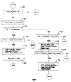
- a converter ratio is calculated by dividing starting turbine speed by the starting engine speed (TQ-Ratio).
- Torque ratio (TQ-RATIO) is calculated from the converter ratio at block 26.
- TOT transmission oil temperature
- TP-Start throttle position at the start of the shift
- Input torque is calculated as indicated by block 22 (TQ-Input-Start) from a torque table input as indicated by block 24 from the throttle position and the engine speed at the start of the shift and the torque ratio.
- the turbine speed rise (TSS-Boost) of which the hydraulic pressure is to be boosted is calculated as indicated at block 28.
- Inputs to block 28 include a transmission oil temperature signal, an adaptive table signal represented by block 30 and a base table signal represented by block 32.
- the turbine speed boost combines the base table signal from block 32 which has inputs of turbine speed and input torque from block 22.
- the adaptive table signal contains information regarding a previous similar shift and has inputs from the input torque block 22 and transmission oil temperature.
- the turbine speed is calculated at the end of the turbine boost as indicated by block 30 wherein the turbine speed boost is added to the turbine speed at the beginning of the shift.
- a first flag is set to boost pressure in the torque phase, and a second flag is set to enable the shift strategy.
- turbine speed at the end of the shift (TSS-SFT-END) is calculated from vehicle speed as indicated at block 34.
- a spark retard value is calculated from a spark retard table indicated at block 36 from engine speed and throttle position or air charge.
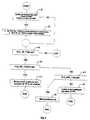
- the turbine speed signal is read.
- the present turbine speed is tested with the turbine speed existing in the last pass through the phase determination logic.
- the present turbine speed is tested against the turbine speed occurring at the end of the turbine boost at block 44 if the present turbine speed is greater than the previous turbine speed.
- the boost flag is cleared and a difference turbine speed is calculated from the current turbine speed minus the turbine speed at the end of the boost.
- the maximum turbine speed is determined at block 48.
- block 50 is entered from block 42. At block 50, it is determined whether the present turbine speed is less than the previously determined maximum turbine speed minus the turbine speed occurring at time T3 as shown in Figure 2.
- a torque and inertia phase pressure strategy is entered within the general upshift pressure strategy. If the shift strategy flag is set as determined by block 58, then the boost phase flag is checked at 60. If the boost phase flag is set, then the clutch pressure is boosted high which is a function of throttle position or air charge as indicated at block 62. If the boost phase flag is not set as tested for at block 60, then the inertia phase flag is checked at block 64. If this flag is set, then the pressure is ramped up as indicated at block 66. If this flag is not set, then the clutch pressure is lowered also as a function of throttle position or air charge.
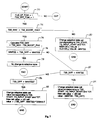
- the shift strategy flag and the inertia phase flag are tested. If both flags are set, then the maximum turbine speed is tested to see if it is greater than the turbine speed at the end of the boost as indicated at block 72.
- a turbine differential speed is calculated as the difference between the maximum turbine speed and the turbine speed at the end of the boost as indicated at block 74.
- this turbine differential speed signal is tested to see if it is between the minimum and maximum turbine speeds. If this difference signal is between the minimum and maximum, no change is made to the adaptive table 30 as indicated in Figure 4 and as indicated at block 78.
- the adaptive table cell corresponding to the beginning turbine speed, transmission oil temperature and the starting input torque is changed at block 80.
- the new cell value equals the old cell value minus the minimum turbine speed.
- the adaptive table cell is changed to a value corresponding to the starting turbine speed, the transmission oil temperature and the starting input torque.
- the new cell value is calculated as the difference between the old cell value and the difference between the minimum turbine speed and the difference in turbine speed previously calculated.
- the adaptive table cell is changed to a value also corresponding to the starting turbine speed, the starting input torque and the transmission oil temperature wherein the new cell value is calculated from the old cell value and the result from the multiplication of the difference between the minimum turbine speed and the difference in turbine speed multiplied by a turbine speed multiplier factor as indicated at block 88.
- the control is adaptive and learns from prior shifts.
- the method and system reduces shift bump and increases smoothness during upshifts.
- the pressure is ramped up to complete the shift quickly and smoothly.
- engine spark timing is reduced in the inertia phase.
Landscapes
- Engineering & Computer Science (AREA)
- General Engineering & Computer Science (AREA)
- Mechanical Engineering (AREA)
- Physics & Mathematics (AREA)
- Fluid Mechanics (AREA)
- Control Of Transmission Device (AREA)
- Control Of Driving Devices And Active Controlling Of Vehicle (AREA)
Applications Claiming Priority (2)
| Application Number | Priority Date | Filing Date | Title |
|---|---|---|---|
| US07/582,444 US5188005A (en) | 1990-09-14 | 1990-09-14 | Method and system for improving smoothness of shifts in an automatic transmission |
| US582444 | 1990-09-14 |
Publications (2)
| Publication Number | Publication Date |
|---|---|
| EP0475585A1 true EP0475585A1 (de) | 1992-03-18 |
| EP0475585B1 EP0475585B1 (de) | 1995-09-20 |
Family
ID=24329173
Family Applications (1)
| Application Number | Title | Priority Date | Filing Date |
|---|---|---|---|
| EP91307344A Expired - Lifetime EP0475585B1 (de) | 1990-09-14 | 1991-08-09 | Verfahren und Einrichtung zur Glättung des Aufwärtsschaltvorganges in einem automatischen Getriebe |
Country Status (4)
| Country | Link |
|---|---|
| US (1) | US5188005A (de) |
| EP (1) | EP0475585B1 (de) |
| JP (1) | JPH04244665A (de) |
| DE (1) | DE69113193T2 (de) |
Cited By (10)
| Publication number | Priority date | Publication date | Assignee | Title |
|---|---|---|---|---|
| EP0583954A1 (de) * | 1992-08-14 | 1994-02-23 | Mitsubishi Jidosha Kogyo Kabushiki Kaisha | Vorrichtung und Verfahren einer Regelung für den Gangwechsel eines automatischen Kraftfahrzeuggetriebes |
| EP0627336A2 (de) * | 1993-06-03 | 1994-12-07 | Aisin Aw Co., Ltd. | Schaltsteuerung für ein automatisches Getriebe |
| GB2286641A (en) * | 1994-02-17 | 1995-08-23 | Acg France | Controlling gear change by controlling clutch fill pressure and shift pressure independently and according to engine speed |
| WO1996017189A1 (de) * | 1994-12-02 | 1996-06-06 | Zf Friedrichshafen Ag | Automatisches getriebe |
| EP0754889A1 (de) * | 1995-07-21 | 1997-01-22 | Société Anonyme dite: REGIE NATIONALE DES USINES RENAULT | Verfahren zur Steuerung des Schaltablaufs beim Heraufschalten in einem Automatikgetriebe |
| GB2310012A (en) * | 1995-11-29 | 1997-08-13 | Siemens Ag | Electronic control of gear-engaging hydraulic pressure in an automatic motor vehicle gearbox |
| WO1998025054A1 (de) * | 1996-12-04 | 1998-06-11 | Voith Turbo Gmbh & Co. Kg | Verfahren zur verbesserung der schaltqualität beim gangwechsel und gangwechselsteuerung |
| EP0899483A2 (de) * | 1997-08-29 | 1999-03-03 | Honda Giken Kogyo Kabushiki Kaisha | Steuereinrichtung für ein hydraulischen betätigtes Kraftfahrzeuggetriebe |
| EP1201970A1 (de) * | 2000-05-22 | 2002-05-02 | Jatco TransTechnology Ltd. | Steuereinheit für automatisches getriebe |
| EP1895202A3 (de) * | 2006-08-28 | 2011-05-11 | Nissan Motor Co., Ltd. | Vorrichtung zum Reduzieren des Schaltrucks in einem Antriebsstrang |
Families Citing this family (48)
| Publication number | Priority date | Publication date | Assignee | Title |
|---|---|---|---|---|
| JPH03292446A (ja) * | 1990-04-06 | 1991-12-24 | Japan Electron Control Syst Co Ltd | 自動変速機の変速作動油圧制御装置 |
| JP2873615B2 (ja) * | 1990-09-11 | 1999-03-24 | 株式会社ユニシアジェックス | 流体伝動装置付変速機の作動油圧制御装置 |
| DE4124603A1 (de) * | 1991-07-25 | 1993-01-28 | Porsche Ag | Verfahren zur steuerung des betaetigungsdrucks in einem stellglied eines elektrohydraulisch gesteuerten kraftfahrzeuggetriebes |
| JP3312918B2 (ja) * | 1991-10-09 | 2002-08-12 | マツダ株式会社 | エンジン及び自動変速機の制御装置 |
| DE69214920T2 (de) * | 1991-12-11 | 1997-03-13 | Toyota Motor Co Ltd | Steuersystem für Antriebseinheit und Automatik-Getriebe |
| JPH05180316A (ja) * | 1992-01-07 | 1993-07-20 | Nissan Motor Co Ltd | 自動変速機の変速制御装置 |
| JP2850615B2 (ja) * | 1992-01-07 | 1999-01-27 | 日産自動車株式会社 | 自動変速機の変速制御装置 |
| US5377111A (en) * | 1992-01-28 | 1994-12-27 | Jatco Corporation | Electronic control apparatus for automatic power transmission of automotive vehicle |
| JP3260438B2 (ja) * | 1992-08-24 | 2002-02-25 | ジヤトコ・トランステクノロジー株式会社 | 自動変速機の制御装置 |
| JP3283323B2 (ja) * | 1993-03-26 | 2002-05-20 | マツダ株式会社 | 自動変速機の変速時油圧制御装置 |
| US5477452A (en) * | 1993-07-15 | 1995-12-19 | Saturn Corporation | Upshift indicator for manual transmission |
| JP3536343B2 (ja) * | 1994-01-20 | 2004-06-07 | マツダ株式会社 | 自動変速機の油圧制御装置 |
| US5518468A (en) * | 1994-06-29 | 1996-05-21 | Ford Motor Company | Compensation for fluid viscosity in automatic transmission friction element engagement |
| US5580332A (en) * | 1995-04-13 | 1996-12-03 | Caterpillar Inc. | Method for determining the fill time of a transmission clutch |
| US5551930A (en) * | 1995-04-13 | 1996-09-03 | Caterpillar Inc. | Adaptive control method for an automatic transmission |
| US5668727A (en) * | 1995-04-28 | 1997-09-16 | General Motors Corporations | Powertrain torque control method |
| JP2828606B2 (ja) * | 1995-05-12 | 1998-11-25 | アイシン・エィ・ダブリュ株式会社 | 自動変速機の制御装置 |
| JP3746100B2 (ja) * | 1996-04-19 | 2006-02-15 | 株式会社日立製作所 | 変速制御装置および制御方法 |
| JP3464354B2 (ja) * | 1996-09-25 | 2003-11-10 | 本田技研工業株式会社 | 車両用油圧作動式変速機の制御装置 |
| JP2932427B2 (ja) * | 1996-09-25 | 1999-08-09 | 本田技研工業株式会社 | 車両用自動変速機の制御装置 |
| JP3687226B2 (ja) * | 1996-09-30 | 2005-08-24 | マツダ株式会社 | 自動変速機の制御装置 |
| US6115661A (en) * | 1998-04-09 | 2000-09-05 | Caterpillar Inc. | End-of-fill detector for a fluid actuated clutch |
| US5950789A (en) * | 1998-04-27 | 1999-09-14 | Caterpillar Inc. | End of fill detector for a fluid actuated clutch |
| JP3360643B2 (ja) * | 1999-04-06 | 2002-12-24 | トヨタ自動車株式会社 | 動力源と無段変速機を備えた車両の制御装置 |
| US6231479B1 (en) * | 1999-10-27 | 2001-05-15 | Ford Global Technologies, Inc. | Closed-loop electronic controller for applying transmission friction clutches |
| JP3562425B2 (ja) * | 2000-03-07 | 2004-09-08 | 日産自動車株式会社 | 自動変速機のアップシフトショック軽減装置 |
| US7139687B2 (en) | 2001-12-31 | 2006-11-21 | The Mathworks, Inc. | Adaptive lookup table: a graphical simulation component for recursively updating numeric data stored in table form |
| US6916270B2 (en) * | 2002-03-27 | 2005-07-12 | Eaton Corporation | Driveline torque interrupt system |
| JP4000967B2 (ja) * | 2002-09-13 | 2007-10-31 | トヨタ自動車株式会社 | ダウンシフト時のトルクダウン制御装置 |
| JP4013131B2 (ja) * | 2002-09-27 | 2007-11-28 | トヨタ自動車株式会社 | 車両用自動変速機の変速時遅角制御装置 |
| JP4119222B2 (ja) * | 2002-10-28 | 2008-07-16 | カルソニックカンセイ株式会社 | 車両用熱交換器の通風装置およびその制御方法 |
| KR100588541B1 (ko) * | 2003-11-17 | 2006-06-14 | 현대자동차주식회사 | 차량의 업시프트 변속시 엔진 제어방법 및 시스템 |
| US20060219509A1 (en) * | 2005-03-31 | 2006-10-05 | Caterpillar Inc. | System and method for controlling engagement of a clutch |
| US8328688B2 (en) * | 2010-01-25 | 2012-12-11 | Ford Global Technologies, Llc | Ratio shift control system and method for a multiple-ratio automatic transmission |
| US8337361B2 (en) | 2010-01-25 | 2012-12-25 | Ford Global Technologies, Llc | Multiple-ratio automatic transmission control method and system for ratio upshifts |
| US8630777B2 (en) * | 2011-05-06 | 2014-01-14 | GM Global Technology Operations LLC | System and method for model-based neutral idle clutch control |
| US8775044B2 (en) | 2011-06-08 | 2014-07-08 | Ford Global Technologies, Llc | Clutch torque trajectory correction to provide torque hole filling during a ratio upshift |
| US8636613B2 (en) | 2011-12-19 | 2014-01-28 | Ford Global Technologies, Llc | Clutch torque trajectory correction to provide torque hole filling during a ratio upshift |
| US8676456B2 (en) * | 2012-03-15 | 2014-03-18 | GM Global Technology Operations LLC | Controlling tip-in bump performance in a transmission |
| US8808141B2 (en) | 2012-05-07 | 2014-08-19 | Ford Global Technologies, Llc | Torque hole filling in a hybrid vehicle during automatic transmission shifting |
| US8938340B2 (en) | 2013-03-13 | 2015-01-20 | Ford Global Technologies, Llc | Automatic transmission shift control based on clutch torque capacity detection using calculated transmission input torque |
| US8894544B2 (en) * | 2013-03-13 | 2014-11-25 | Ford Global Technologies, Llc | Automatic transmission shift control based on transmission input shaft torque signal |
| US9056613B2 (en) | 2013-11-06 | 2015-06-16 | Ford Global Technologies, Llc | System and method for upshift torque modification using an upstream clutch in a hybrid vehicle |
| US10399557B2 (en) | 2017-11-10 | 2019-09-03 | Ford Global Technologies, Llc | Engine/motor torque control for torque hole filling in a hybrid vehicle during automatic transmission shifting |
| JP2021060062A (ja) | 2019-10-04 | 2021-04-15 | マツダ株式会社 | 自動変速機の制御装置 |
| JP2021060061A (ja) | 2019-10-04 | 2021-04-15 | マツダ株式会社 | 自動変速機の制御装置 |
| JP2021038776A (ja) * | 2019-09-02 | 2021-03-11 | マツダ株式会社 | 自動変速機の制御装置 |
| CN115217962B (zh) * | 2022-07-15 | 2023-11-14 | 奇瑞商用车(安徽)有限公司 | 换挡转矩交互阶段的发动机扭矩补偿控制方法及系统 |
Citations (4)
| Publication number | Priority date | Publication date | Assignee | Title |
|---|---|---|---|---|
| EP0235892A1 (de) * | 1986-02-12 | 1987-09-09 | General Motors Corporation | Herunterschalten unter Last von Kupplung zu Kupplung in einem automatischen Getriebe eines Kraftfahrzeugs |
| US4890515A (en) * | 1986-07-07 | 1990-01-02 | Toyota Jidosha Kabushiki Kaisha | System for integrally controlling automatic transmission and engine |
| EP0385438A2 (de) * | 1989-02-28 | 1990-09-05 | Nissan Motor Co., Ltd. | Leitungsdrucksteuerung für automatische Kraftfahrzeuggetriebe |
| EP0435373A2 (de) * | 1989-12-26 | 1991-07-03 | General Motors Corporation | Verfahren zum Steuern der Gangwechsel in automatischen Getrieben |
Family Cites Families (18)
| Publication number | Priority date | Publication date | Assignee | Title |
|---|---|---|---|---|
| US3822771A (en) * | 1971-12-27 | 1974-07-09 | Caterpillar Tractor Co | Interrelated controls for a motor and slipping clutch |
| US3991865A (en) * | 1974-02-28 | 1976-11-16 | Kabushiki Kaisha Komatsu Seisakusho | Device for gradually increasing hydraulic pressure |
| JPS60175855A (ja) * | 1984-02-23 | 1985-09-10 | Nissan Motor Co Ltd | 自動変速機の変速シヨツク軽減装置 |
| US4665770A (en) * | 1985-03-18 | 1987-05-19 | Ford Motor Company | Control system for a multiple ratio transmission having a lockup clutch torque converter |
| US4633738A (en) * | 1985-07-19 | 1987-01-06 | Ford Motor Company | Control valve system for a four speed ratio automatic transmission including a dual range regulator valve for controlling independently two upshift ratio changes |
| US4711329A (en) * | 1985-08-28 | 1987-12-08 | Kubota, Ltd. | Hydraulic circuit construction for power shift transmission |
| US4748870A (en) * | 1985-09-05 | 1988-06-07 | Nissan Motor Co., Ltd. | Control system for automatic transmission |
| US4653350A (en) * | 1985-11-29 | 1987-03-31 | General Motors Corporation | Adaptive direct pressure shift control for a motor vehicle transmission |
| US4792902A (en) * | 1985-12-12 | 1988-12-20 | Ford Motor Company | Engine ignition timing for a clutch engagement control system |
| JPS62241738A (ja) * | 1986-04-14 | 1987-10-22 | Toyota Motor Corp | 車両用自動変速機及びエンジンの一体制御装置 |
| JP2696819B2 (ja) * | 1986-10-08 | 1998-01-14 | 日産自動車株式会社 | 自動変速機の変速シヨツク軽減装置 |
| US4790418A (en) * | 1987-04-30 | 1988-12-13 | Ford Motor Company | Transmission clutch loop transfer control |
| US4855913A (en) * | 1987-05-29 | 1989-08-08 | J. I. Case Company | Electronic control system for powershift transmission |
| US4871048A (en) * | 1987-09-21 | 1989-10-03 | Dresser Industries, Inc. | Control system for vehicle transmissions |
| US4982622A (en) * | 1988-07-12 | 1991-01-08 | Aisin Aw Co., Ltd. | Hydraulic pressure control device for automatic transmission |
| US4949264A (en) * | 1988-09-29 | 1990-08-14 | Kubota, Ltd. | Transmission having electromagnetic proportional reduction valve |
| US4989477A (en) * | 1990-01-11 | 1991-02-05 | General Motors Corporation | Double transition closed throttle downshift control in an automatic transmissions |
| US5046383A (en) * | 1990-07-16 | 1991-09-10 | General Motors Corporation | Acceleration-based control of power-on clutch-to-clutch upshifting in an automatic transmission |
-
1990
- 1990-09-14 US US07/582,444 patent/US5188005A/en not_active Expired - Lifetime
-
1991
- 1991-08-09 DE DE69113193T patent/DE69113193T2/de not_active Expired - Lifetime
- 1991-08-09 EP EP91307344A patent/EP0475585B1/de not_active Expired - Lifetime
- 1991-09-11 JP JP3231610A patent/JPH04244665A/ja active Pending
Patent Citations (4)
| Publication number | Priority date | Publication date | Assignee | Title |
|---|---|---|---|---|
| EP0235892A1 (de) * | 1986-02-12 | 1987-09-09 | General Motors Corporation | Herunterschalten unter Last von Kupplung zu Kupplung in einem automatischen Getriebe eines Kraftfahrzeugs |
| US4890515A (en) * | 1986-07-07 | 1990-01-02 | Toyota Jidosha Kabushiki Kaisha | System for integrally controlling automatic transmission and engine |
| EP0385438A2 (de) * | 1989-02-28 | 1990-09-05 | Nissan Motor Co., Ltd. | Leitungsdrucksteuerung für automatische Kraftfahrzeuggetriebe |
| EP0435373A2 (de) * | 1989-12-26 | 1991-07-03 | General Motors Corporation | Verfahren zum Steuern der Gangwechsel in automatischen Getrieben |
Non-Patent Citations (3)
| Title |
|---|
| PATENT ABSTRACTS OF JAPAN vol. 013, no. 071 (M-799) 17 February 1989, & JP-A-63 270971 (JAPAN ELECTRONIC) 08 November 1988, * |
| PATENT ABSTRACTS OF JAPAN vol. 013, no. 411 (M-869) 11 September 1989, & JP-A-01 150056 (TOYOTA) 13 June 1989, * |
| PATENT ABSTRACTS OF JAPAN vol. 014, no. 495 (M-1041) 29 October 1990, & JP-A-02 203066 (MAZDA) 13 August 1990, * |
Cited By (21)
| Publication number | Priority date | Publication date | Assignee | Title |
|---|---|---|---|---|
| US5445579A (en) * | 1992-08-14 | 1995-08-29 | Mitsubishi Jidosha Kogyo Kabushiki Kaisha | Speed change control apparatus and method for an automatic transmission in a vehicle |
| EP0583954A1 (de) * | 1992-08-14 | 1994-02-23 | Mitsubishi Jidosha Kogyo Kabushiki Kaisha | Vorrichtung und Verfahren einer Regelung für den Gangwechsel eines automatischen Kraftfahrzeuggetriebes |
| EP0627336A2 (de) * | 1993-06-03 | 1994-12-07 | Aisin Aw Co., Ltd. | Schaltsteuerung für ein automatisches Getriebe |
| EP0627336A3 (de) * | 1993-06-03 | 1996-05-08 | Aisin Aw Co | Schaltsteuerung für ein automatisches Getriebe. |
| US5583768A (en) * | 1993-06-03 | 1996-12-10 | Aisin Aw Co., Ltd. | Shift control system for preventing engine racing |
| GB2286641B (en) * | 1994-02-17 | 1998-01-07 | Acg France | Method and apparatus for controlling a gear change in an automatic transmission |
| GB2286641A (en) * | 1994-02-17 | 1995-08-23 | Acg France | Controlling gear change by controlling clutch fill pressure and shift pressure independently and according to engine speed |
| WO1996017189A1 (de) * | 1994-12-02 | 1996-06-06 | Zf Friedrichshafen Ag | Automatisches getriebe |
| US5911648A (en) * | 1994-12-02 | 1999-06-15 | Zf Friedrichshafen Ag | Automatic transmission control method including shifting aberration regulating phase |
| EP0754889A1 (de) * | 1995-07-21 | 1997-01-22 | Société Anonyme dite: REGIE NATIONALE DES USINES RENAULT | Verfahren zur Steuerung des Schaltablaufs beim Heraufschalten in einem Automatikgetriebe |
| FR2736983A1 (fr) * | 1995-07-21 | 1997-01-24 | Renault | Procede de controle du deroulement des changements de rapports montants sur une transmission automatique |
| GB2310012B (en) * | 1995-11-29 | 1999-08-04 | Siemens Ag | Control device for an automatic motor-vehicle gearbox |
| GB2310012A (en) * | 1995-11-29 | 1997-08-13 | Siemens Ag | Electronic control of gear-engaging hydraulic pressure in an automatic motor vehicle gearbox |
| US6101440A (en) * | 1995-11-29 | 2000-08-08 | Siemens Aktiengesellschaft | Controller for an automatic motor vehicle transmission |
| WO1998025054A1 (de) * | 1996-12-04 | 1998-06-11 | Voith Turbo Gmbh & Co. Kg | Verfahren zur verbesserung der schaltqualität beim gangwechsel und gangwechselsteuerung |
| EP0899483A3 (de) * | 1997-08-29 | 1999-07-14 | Honda Giken Kogyo Kabushiki Kaisha | Steuereinrichtung für ein hydraulischen betätigtes Kraftfahrzeuggetriebe |
| US6024663A (en) * | 1997-08-29 | 2000-02-15 | Honda Giken Kogyo Kabushiki Kaisha | Control apparatus for hydraulically operated vehicular transmission |
| EP0899483A2 (de) * | 1997-08-29 | 1999-03-03 | Honda Giken Kogyo Kabushiki Kaisha | Steuereinrichtung für ein hydraulischen betätigtes Kraftfahrzeuggetriebe |
| EP1201970A1 (de) * | 2000-05-22 | 2002-05-02 | Jatco TransTechnology Ltd. | Steuereinheit für automatisches getriebe |
| EP1201970A4 (de) * | 2000-05-22 | 2006-05-03 | Jatco Transtechnology Ltd | Steuereinheit für automatisches getriebe |
| EP1895202A3 (de) * | 2006-08-28 | 2011-05-11 | Nissan Motor Co., Ltd. | Vorrichtung zum Reduzieren des Schaltrucks in einem Antriebsstrang |
Also Published As
| Publication number | Publication date |
|---|---|
| DE69113193D1 (de) | 1995-10-26 |
| DE69113193T2 (de) | 1996-02-22 |
| JPH04244665A (ja) | 1992-09-01 |
| US5188005A (en) | 1993-02-23 |
| EP0475585B1 (de) | 1995-09-20 |
Similar Documents
| Publication | Publication Date | Title |
|---|---|---|
| US5188005A (en) | Method and system for improving smoothness of shifts in an automatic transmission | |
| EP0476832B1 (de) | Elektronisches Steuerungssystem für vielstufiges Getriebe mit Systemdrucksteuerung | |
| USRE38615E1 (en) | System and method for decreasing ratio changing time in electronically enhanced powertrain systems | |
| US5954776A (en) | Hydraulic control apparatus of automatic transmission | |
| EP0352551B1 (de) | Hochschaltlogik | |
| EP0178110B1 (de) | Verfahren zum Betätigen eines automatischen Getriebes | |
| EP0142046B1 (de) | Verfahren und Vorrichtung zur automatischen Steuerung der Fahrgeschwindigkeit mit dem Getriebe | |
| US5441462A (en) | Clutch disengage logic | |
| US5016494A (en) | Jolt control for drive system | |
| US5046175A (en) | Method of detecting clutch tie-up during transmission shifting | |
| EP0352803B1 (de) | Gangschaltungssteuerung für Antriebsstrang | |
| US5842376A (en) | System and method for decreasing ratio changing time by actuating inertia brake while the master clutch is engaged in electronically enhanced powertrain systems | |
| US6503165B1 (en) | Hydraulic control device for automatic transmission | |
| JPH0650145B2 (ja) | オートトランスミッションにおけるギア切換え制御方法 | |
| JP3189214B2 (ja) | 自動変速機の液圧制御装置 | |
| EP0351824B1 (de) | Systemdrucksteuerung für ein automatisches Getriebe | |
| US5343782A (en) | Anti-flare method using offgoing slip speed and rate of change of slip-speed to determine pressure compensation for incoming clutch | |
| JP2962111B2 (ja) | 自動変速機の油圧制御装置 | |
| EP0802354B1 (de) | Vorrichtung und Verfahren zur Steuerung eines Automatikgetriebes von einem Kraftfahrzeug | |
| US6461273B1 (en) | Automated transmission upshift brake control | |
| EP0360980B1 (de) | Motorlastabhängige Hydraulikdruckregelung für Fahrzeug-Automatikgetriebe | |
| JP3189216B2 (ja) | 自動変速機の液圧制御装置 | |
| US4792901A (en) | Method for controlling AMT system including after transmission gear change fuel control | |
| JPH055688B2 (de) | ||
| EP1158218B1 (de) | Hochschaltsteuerung für ein automatisiertes Getriebe, in der die angehende Bremse vor thermischen Schäden geschützt wird |
Legal Events
| Date | Code | Title | Description |
|---|---|---|---|
| PUAI | Public reference made under article 153(3) epc to a published international application that has entered the european phase |
Free format text: ORIGINAL CODE: 0009012 |
|
| AK | Designated contracting states |
Kind code of ref document: A1 Designated state(s): DE FR GB |
|
| 17P | Request for examination filed |
Effective date: 19920827 |
|
| 17Q | First examination report despatched |
Effective date: 19940331 |
|
| GRAA | (expected) grant |
Free format text: ORIGINAL CODE: 0009210 |
|
| AK | Designated contracting states |
Kind code of ref document: B1 Designated state(s): DE FR GB |
|
| REF | Corresponds to: |
Ref document number: 69113193 Country of ref document: DE Date of ref document: 19951026 |
|
| ET | Fr: translation filed | ||
| PLBE | No opposition filed within time limit |
Free format text: ORIGINAL CODE: 0009261 |
|
| STAA | Information on the status of an ep patent application or granted ep patent |
Free format text: STATUS: NO OPPOSITION FILED WITHIN TIME LIMIT |
|
| 26N | No opposition filed | ||
| REG | Reference to a national code |
Ref country code: FR Ref legal event code: D6 |
|
| REG | Reference to a national code |
Ref country code: FR Ref legal event code: CD Ref country code: FR Ref legal event code: TP |
|
| REG | Reference to a national code |
Ref country code: GB Ref legal event code: IF02 |
|
| REG | Reference to a national code |
Ref country code: FR Ref legal event code: CD Ref country code: FR Ref legal event code: CA |
|
| PGFP | Annual fee paid to national office [announced via postgrant information from national office to epo] |
Ref country code: FR Payment date: 20100819 Year of fee payment: 20 Ref country code: DE Payment date: 20100831 Year of fee payment: 20 |
|
| PGFP | Annual fee paid to national office [announced via postgrant information from national office to epo] |
Ref country code: GB Payment date: 20100708 Year of fee payment: 20 |
|
| REG | Reference to a national code |
Ref country code: DE Ref legal event code: R071 Ref document number: 69113193 Country of ref document: DE |
|
| REG | Reference to a national code |
Ref country code: DE Ref legal event code: R071 Ref document number: 69113193 Country of ref document: DE |
|
| REG | Reference to a national code |
Ref country code: GB Ref legal event code: PE20 Expiry date: 20110808 |
|
| PG25 | Lapsed in a contracting state [announced via postgrant information from national office to epo] |
Ref country code: GB Free format text: LAPSE BECAUSE OF EXPIRATION OF PROTECTION Effective date: 20110808 |
|
| PG25 | Lapsed in a contracting state [announced via postgrant information from national office to epo] |
Ref country code: DE Free format text: LAPSE BECAUSE OF EXPIRATION OF PROTECTION Effective date: 20110810 |