EP0475063A2 - Dispositif de contrôle d'une machine à mouler par injection ayant plusieurs unités d'injection - Google Patents
Dispositif de contrôle d'une machine à mouler par injection ayant plusieurs unités d'injection Download PDFInfo
- Publication number
- EP0475063A2 EP0475063A2 EP91113035A EP91113035A EP0475063A2 EP 0475063 A2 EP0475063 A2 EP 0475063A2 EP 91113035 A EP91113035 A EP 91113035A EP 91113035 A EP91113035 A EP 91113035A EP 0475063 A2 EP0475063 A2 EP 0475063A2
- Authority
- EP
- European Patent Office
- Prior art keywords
- injection
- injection apparatus
- target value
- controller
- control unit
- Prior art date
- Legal status (The legal status is an assumption and is not a legal conclusion. Google has not performed a legal analysis and makes no representation as to the accuracy of the status listed.)
- Granted
Links
Images

Classifications
-
- B—PERFORMING OPERATIONS; TRANSPORTING
- B29—WORKING OF PLASTICS; WORKING OF SUBSTANCES IN A PLASTIC STATE IN GENERAL
- B29C—SHAPING OR JOINING OF PLASTICS; SHAPING OF MATERIAL IN A PLASTIC STATE, NOT OTHERWISE PROVIDED FOR; AFTER-TREATMENT OF THE SHAPED PRODUCTS, e.g. REPAIRING
- B29C45/00—Injection moulding, i.e. forcing the required volume of moulding material through a nozzle into a closed mould; Apparatus therefor
- B29C45/16—Making multilayered or multicoloured articles
-
- B—PERFORMING OPERATIONS; TRANSPORTING
- B29—WORKING OF PLASTICS; WORKING OF SUBSTANCES IN A PLASTIC STATE IN GENERAL
- B29C—SHAPING OR JOINING OF PLASTICS; SHAPING OF MATERIAL IN A PLASTIC STATE, NOT OTHERWISE PROVIDED FOR; AFTER-TREATMENT OF THE SHAPED PRODUCTS, e.g. REPAIRING
- B29C45/00—Injection moulding, i.e. forcing the required volume of moulding material through a nozzle into a closed mould; Apparatus therefor
- B29C45/17—Component parts, details or accessories; Auxiliary operations
- B29C45/76—Measuring, controlling or regulating
Definitions
- the present invention relates to a controller of an injection molding machine for performing molding with a plurality of injection apparatuses.
- an injection molding machine in which a plurality of kinds of materials to be molded are injected into a cavity of a single injection mold to fill the cavity so that, for instance, multi-color molding or sandwich molding is performed is known in, for example, Japanese Patent Publication Nos. 63-44047 and 41-16794.
- Fig. 2 shows an example of the injection molding machine of this type.
- numeral 5 denotes a base.
- a mold clamping apparatus 6 for supporting a mold 4 is disposed at one side of the base 5 and two injection apparatuses, that is, a main injection apparatus 2 and a sub-injection apparatus 3 are disposed at the other side of the base.
- the injection apparatuses 2 and 3 are placed on a slide plate 7 which is slidably movable in directions towards and away from the mold clamping apparatus 6 and have ends coupled with a usual injection nozzle 8.
- 9 is a driving portion for moving the slide plate 7.
- material Ms to be molded for a surface side is previously injected from the main injection apparatus 2 and material Mc to be molded for a core side is then injected by the sub-injection apparatus 3 while the material Ms is injected.
- the materials Ms and Mc are joined in the injection nozzle 8 to enter the cavity of the mold 4 from one injection inlet so that the cavity of the mold 4 is filled with the materials.
- the materials Ms and Mc flow in the cavity in layers through a single sprue portion and a gate portion is finally sealed by the material Ms for the surface side so that the filling is completed.
- the materials Ms and Mc are also injected substantially simultaneously, while in the flowing process the materials Ms and Mc are separated to the outer side and the inner side, respectively.
- the filled state of the precedently injected material Ms influences the subsequent injection and filling condition greatly. Accordingly, in order to manufacture the molded product A stably, it is necessary to balance properly the rheology characteristics of the materials Ms and Mc of the surface and core sides and to control the molding conditions for controlling the states of flow of the materials Ms and Mc precisely.
- a conventional controller of an injection molding machine of this type has established process control amounts such as speed, pressure and process change-over position in the injection apparatuses exactly and has effected feedback control for each of the injection apparatuses.
- An embodiment of the present invention can provide a controller of an injection molding machine capable of achieving improved uniformity and quality of a molded product by preventing dispersion of the molded state such as thickness for each shot to obtain uniform mechanical characteristics and capable of contributing to reduction of costs by reducing the occurrence of inferior products.
- an embodiment of the present invention can provide a controller of an injection molding machine in which even if molding conditions established once are changed, it is sufficient that only molding conditions for a specific injection apparatus are changed, and a reduction of labor costs can be attained.
- a controller 1 comprises a first control unit 11 for controlling operation of a main injection apparatus 2, which is a specific injection apparatus, in accordance with a previously set target value Xp, for example, in feedback manner, a physical quantity detection unit 12 for detecting physical quantities Yp, (e.g. screw speed, screw position, injection pressure, temperature or the like) relating to the operation of the main injection apparatus 2, and a second control unit 13 for obtaining a linkage target value Xo for a sub-injection apparatus 2, which is another injection apparatus, from the detected physical quantity (detection value Yp) to control operation of the sub-injection apparatus 3 in accordance with the linkage target value Xo in a feedback manner, for example.
- the second control unit 13 includes an operation function unit 14 for calculating a linkage target value Xo of the sub-injection apparatus 3 on the basis of the detection value Yp.
- the physical quantity detection unit 12 detects a physical quantity relating to the operation of the main injection apparatus 2 to obtain the detection value Yp.
- the first control unit 11 compares the detection value Yp with the set target value Xp and feedback controls the operation of the main injection apparatus 2 so that the detection value Yp is equal to the set target value Xp.
- the detection value Yp is supplied from the main injection apparatus 2 and a linkage target value Xo for the sub-injection apparatus 3 is calculated by the operation function unit 14.
- the second control unit 13 compares the linkage target value Xo with the physical quantity (detection value Yq) relating to the operation of the sub-injection apparatus 3 detected from the sub-injection apparatus 3 and feedback controls the operation of the sub-injection apparatus 3 so that the linkage target value Xo is equal to the detection value Yq. In this manner, the sub-injection apparatus 3 is controlled in interlocked relationship with the operation state of the main injection apparatus 2 so that the operation timing therebetween is synchronized.
- the injection molding machine shown in Fig. 2 can be utilized for this embodiment.
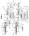
- a controller 1 included in the injection molding machine is configured as shown in Fig. 1.
- FIG. 1 2 is a main injection apparatus constituting the specific injection apparatus, and 3 is a sub-injection apparatus constituting another injection apparatus.
- the main injection apparatus 2 comprises a heating cylinder 21 having a nozzle portion 8p disposed at a front end and a hopper 20 disposed at a back portion, a screw 22 inserted into the heating cylinder 21 and an injection cylinder 23 for moving the screw 22 forward and backward and connected to an oil pressure circuit 24.
- the sub-injection apparatus 3 comprises a heating cylinder 31 having a nozzle portion 8q disposed at a front end and a hopper 30 disposed at a back portion, a screw 32 inserted into the heating cylinder 31 and an injection cylinder 33 for moving the screw 32 forward and backward and connected to an oil pressure circuit 34.
- the nozzle portion 8p and the nozzle portion 8q are connected to a common injection nozzle 8.
- a main injection apparatus 2 comprises a physical quantity detection unit 12, that is, a position sensor 12p for detecting a position of the screw 22, and a first control unit 11 including a velocity conversion unit 25, comparators 26 and 27, a process controller 40, an amplification operation unit 28 and a servo valve 29.
- the sub-injection apparatus 3 comprises a position sensor 12q for detecting a position of the screw 32 and a second control unit 13 including a velocity conversion unit 35, comparators 36 and 37 a process controller (40), an amplification operation unit 39, a servo valve 41, an operation function unit 14, a comparator 38 and interlocked change-over switches 42, 43.
- a physical quantity detection unit 12 that is, a position sensor 12p for detecting a position of the screw 22, and a first control unit 11 including a velocity conversion unit 25, comparators 26 and 27, a process controller 40, an amplification operation unit 28 and a servo valve 29.
- the sub-injection apparatus 3 comprises a position sensor 12q for detecting a
- the control unit 1 establishes an independent control mode in which the main injection apparatus 2 and the sub-injection apparatus 3 are controlled independently when a movable contact a of the interlocked change-over switches 42 and 43 is switched to a stationary contact c. Further, when movable contact a of the change-over switches 42 and 43 is switched to a stationary contact b, an interlock control mode is established in which the main injection apparatus 2 and the sub-injection apparatus 3 are controlled in interlocked relationship with each other.
- a position of the screw 22 is detected by the position sensor 12p and the position information Dp is converted into velocity information (detection value Yp) by the velocity conversion unit 25.
- the comparator 26 is supplied with the detection value Yp and the set target value Xp established previously in the process controller 40 and produces a difference value Kp between the detection value Yp and the target value Xp.
- the difference value Kp is supplied to the servo valve 29 through the amplification operation unit 28.
- the injection cylinder 23 is controlled and the feedback control is made so that the velocity of the screw 22 is equal to the set target value Xp.
- the comparator 27 is supplied with the position information Dp detected by the position sensor 12p and a change-over position set value Pp established previously in the process controller 40 and supplies a coincidence signal Sp to the process controller 40 when the position information Dp is coincident with the change-over position set value Pp.
- the predetermined process change-over is made by the timing of the coincidence signal Sp.
- the position information Dq of the position sensor 12q is converted into velocity information (detection value Yq) by means of the velocity conversion unit 35.
- the comparator 36 is supplied with the detection value Yq and the target value Xq established previously in the process controller 40 and produces a difference value Kq between the detection value Yq and the target value Xq.
- the difference value Kq is supplied to the servo valve 41 through the amplification operation unit 39.
- the injection cylinder 33 is controlled and the feedback control is made so that the velocity of the screw 32 is equal to the target value Xq.
- the comparator 37 is supplied with the position information Dq detected by the position sensor 12q and a change-over position set value Pq established previously in the process controller 40 and supplies a coincidence signal Sq to the process controller 40 when the position information Dq is coincident with the change-over position set value Pq.
- the interlock control mode will now be described. In this case, the same independent feedback control as in the independent control mode is made in the main injection apparatus 2.
- the sub-injection apparatus 3 is controlled in interlocked relationship with the operation state of the main injection apparatus 2. That is, the detection value Yp produced by the velocity conversion unit 25 of the main injection apparatus 2 is supplied to the comparator 38 through the operation function unit 14. In this case, the detection value Yp is used as the target value, that is, the linkage target value Xo in the sub-injection apparatus 3. Accordingly, in order to effect matching to the sub-injection apparatus 3, the detection value Yp is converted into a linkage target value Xo by the operation function unit 14 having a fixed magnification (amplification/attenuation factor) set therein.
- the detection value Yq detected by the position sensor 12q of the sub-injection apparatus 3 is supplied to the comparator 38 through the change-over switch 42.
- the comparator 38 compares the detection value Yq with the linkage target value Xo and produces a difference value Ko.
- the difference value Ko is supplied through the change-over switch 43 to the amplification operation unit 39 to be subjected to a necessary signal processing, and an output of the amplification unit 39 is supplied to the servo valve 41.
- the injection cylinder 33 is controlled and the feedback control is made so that the velocity of the screw 32 is coincident with the linkage target value Xo.
- the sub-injection apparatus 3 is always feedback-controlled in interlocked relationship with the main injection apparatus 2 and even if the main injection apparatus 2 is operated unstably due to the external disturbance or the like, the sub-injection apparatus 3 is operated to follow the operation of the main injection apparatus 2. Consequently, the relative operation timings between the main injection apparatus 2 and the sub-injection apparatus 3 are coincident with each other to obtain a molded product with stable quality.
- the main injection apparatus is feedback-controlled in the described embodiment, but in other embodiments it may be controlled in an open loop manner.
- the operation of the main injection apparatus is controlled in the open loop manner on the basis of the previously set target value, while a physical quantity relating to the operation of the main injection apparatus is detected to obtain the linkage target value for the sub-injection apparatus on the basis of the detected physical value, so that the operation of the sub-injection apparatus is controlled in an open loop manner on the basis of the linkage target value.
- the screw velocity is used as a detected physical quantity in the described embodiment, but various physical quantities such as an injection pressure, a screw position, a temperature or the like can be used similarly.
- the injection apparatus need not be of the oil driven type shown in the described embodiment, but could also be a servo motor driven type.
- the controller of the present invention can be utilized in the injection process as well as any molding process such as a measuring process, a pressure holding process and the like. Other configurations, numbers (for example, different numbers of injection apparatuses), methods and the like can be modified.
- An embodiment of the present invention provides a controller for an injection molding apparatus having a plurality of injection apparatuses from which different molding materials are injected into a cavity of a mold to fill the cavity so that molding is performed.
- the controller includes a first control unit for controlling operation of a specific injection apparatus on the basis of a previously set target value, for example, in the feedback control manner, a physical quantity detection unit for detecting a physical quantity (e.g. screw velocity, or screw position, or injection pressure, or temperature of the like) concerning the operation of the specific injection apparatus and a second control unit for obtaining a linkage target value for another injection apparatus from the detected physical quantity (detection value) to control operation of the other injection apparatus on the basis of the linkage target value, for example, in the feedback control manner.
- a physical quantity detection unit for detecting a physical quantity (e.g. screw velocity, or screw position, or injection pressure, or temperature of the like) concerning the operation of the specific injection apparatus
- a second control unit for obtaining a linkage target value for another
- the second control unit includes an operation function unit for calculating the linkage target value of the other injection apparatus from the detection value.
- the other injection apparatus is controlled in interlocked relationship with the operation state of the specific injection apparatus and the operation timings between the specific and other injection apparatuses is synchronized.
Landscapes
- Engineering & Computer Science (AREA)
- Manufacturing & Machinery (AREA)
- Mechanical Engineering (AREA)
- Injection Moulding Of Plastics Or The Like (AREA)
Applications Claiming Priority (2)
| Application Number | Priority Date | Filing Date | Title |
|---|---|---|---|
| JP207191/90 | 1990-08-04 | ||
| JP2207191A JPH0649315B2 (ja) | 1990-08-04 | 1990-08-04 | 射出成形機の制御方法及び装置 |
Publications (4)
| Publication Number | Publication Date |
|---|---|
| EP0475063A2 true EP0475063A2 (fr) | 1992-03-18 |
| EP0475063A3 EP0475063A3 (en) | 1992-05-27 |
| EP0475063B1 EP0475063B1 (fr) | 1994-12-14 |
| EP0475063B2 EP0475063B2 (fr) | 1997-10-08 |
Family
ID=16535758
Family Applications (1)
| Application Number | Title | Priority Date | Filing Date |
|---|---|---|---|
| EP91113035A Expired - Lifetime EP0475063B2 (fr) | 1990-08-04 | 1991-08-02 | Dispositif de contrÔle d'une machine à mouler par injection ayant plusieurs unités d'injection |
Country Status (5)
| Country | Link |
|---|---|
| US (1) | US5186954A (fr) |
| EP (1) | EP0475063B2 (fr) |
| JP (1) | JPH0649315B2 (fr) |
| CA (1) | CA2048024C (fr) |
| DE (1) | DE69105880T3 (fr) |
Cited By (2)
| Publication number | Priority date | Publication date | Assignee | Title |
|---|---|---|---|---|
| DE19808679C1 (de) * | 1998-03-02 | 1999-07-08 | Karl Hehl | Verfahren zur Konvertierung von Einstelldaten |
| WO2001041996A1 (fr) * | 1999-12-08 | 2001-06-14 | Plabber Holding S.A. | Commande d'une machine a injecter presentant un moule et au moins deux unites d'injection |
Families Citing this family (12)
| Publication number | Priority date | Publication date | Assignee | Title |
|---|---|---|---|---|
| DE4335403C1 (de) * | 1993-10-18 | 1994-12-15 | Karl Hehl | Hydraulikeinrichtung |
| JP2736753B2 (ja) * | 1994-11-28 | 1998-04-02 | 日精樹脂工業株式会社 | 射出成形機の駆動制御方法及び装置 |
| US5601773A (en) * | 1995-05-12 | 1997-02-11 | Cincinnati Milacron Inc. | Co-injection machine |
| US6994810B2 (en) * | 2000-04-06 | 2006-02-07 | Mgs Mfg. Group, Inc. | Multi-shot injection molding arrangement |
| US7393199B2 (en) * | 2000-04-06 | 2008-07-01 | Mgs Mfg. Group, Inc. | Multi-shot injection molding arrangement |
| CA2582178C (fr) * | 2000-05-16 | 2010-10-12 | Techmire Ltd. | Systeme de moulage sous pression a sections multiples sur glissiere |
| JP2003181873A (ja) * | 2001-12-21 | 2003-07-02 | Toshiba Mach Co Ltd | 射出成形機の樹脂替え方法及びサンドイッチ成形品 |
| US7390184B2 (en) | 2005-11-09 | 2008-06-24 | Centoco Plastics Limited | Dual injection manifold |
| DE102006010310A1 (de) * | 2006-03-07 | 2007-09-13 | Krauss-Maffei Kunststofftechnik Gmbh | Vorrichtung und Verfahren zur Herstellung von Mehrkomponenten-Kunststoffteilen |
| US8033808B2 (en) * | 2007-08-24 | 2011-10-11 | Delta Pt, Llc | Pressure compensating molding system |
| US8715547B2 (en) | 2011-02-24 | 2014-05-06 | Mold-Masters (2007) Limited | Closed loop control of auxiliary injection unit |
| CN114289699B (zh) * | 2021-12-22 | 2023-09-12 | 广州小鹏汽车科技有限公司 | 压铸机的控制方法、控制装置、压铸机及存储介质 |
Citations (4)
| Publication number | Priority date | Publication date | Assignee | Title |
|---|---|---|---|---|
| FR2141919A1 (fr) * | 1971-06-14 | 1973-01-26 | Hanning Robert | |
| EP0199823A1 (fr) * | 1984-10-31 | 1986-11-05 | Fanuc Ltd. | Dispositif de controle pour machines de moulage par injection |
| EP0329810A1 (fr) * | 1988-02-25 | 1989-08-30 | Idemitsu Petrochemical Co. Ltd. | Procédé de fabrication de feuilles en résine thermoplastique et installation à cet effet |
| EP0372899A1 (fr) * | 1988-12-08 | 1990-06-13 | Trinova Limited | Procédé et dispositif de commande simultanée de deux ou plusieurs variables dépendantes |
Family Cites Families (5)
| Publication number | Priority date | Publication date | Assignee | Title |
|---|---|---|---|---|
| US4208176A (en) * | 1975-06-16 | 1980-06-17 | Litton Industrial Products, Inc. | Time independent cycle control for plastic injection molding machines |
| US4325896A (en) * | 1975-10-08 | 1982-04-20 | Solid Controls, Inc. | Electro-hydraulic ram control apparatus |
| US4507255A (en) * | 1983-03-30 | 1985-03-26 | Orion Kasei Kabushiki Kaisha | Process and apparatus for injection-molding foamed article |
| US4855095A (en) * | 1987-12-30 | 1989-08-08 | Toshiba Kikai Kabushiki Kaisha | Method for injection compression molding |
| JP2755110B2 (ja) * | 1993-06-11 | 1998-05-20 | 日本鋼管株式会社 | 爆轟圧加工装置 |
-
1990
- 1990-08-04 JP JP2207191A patent/JPH0649315B2/ja not_active Expired - Lifetime
-
1991
- 1991-07-26 CA CA002048024A patent/CA2048024C/fr not_active Expired - Fee Related
- 1991-07-30 US US07/737,484 patent/US5186954A/en not_active Expired - Lifetime
- 1991-08-02 EP EP91113035A patent/EP0475063B2/fr not_active Expired - Lifetime
- 1991-08-02 DE DE69105880T patent/DE69105880T3/de not_active Expired - Fee Related
Patent Citations (4)
| Publication number | Priority date | Publication date | Assignee | Title |
|---|---|---|---|---|
| FR2141919A1 (fr) * | 1971-06-14 | 1973-01-26 | Hanning Robert | |
| EP0199823A1 (fr) * | 1984-10-31 | 1986-11-05 | Fanuc Ltd. | Dispositif de controle pour machines de moulage par injection |
| EP0329810A1 (fr) * | 1988-02-25 | 1989-08-30 | Idemitsu Petrochemical Co. Ltd. | Procédé de fabrication de feuilles en résine thermoplastique et installation à cet effet |
| EP0372899A1 (fr) * | 1988-12-08 | 1990-06-13 | Trinova Limited | Procédé et dispositif de commande simultanée de deux ou plusieurs variables dépendantes |
Cited By (2)
| Publication number | Priority date | Publication date | Assignee | Title |
|---|---|---|---|---|
| DE19808679C1 (de) * | 1998-03-02 | 1999-07-08 | Karl Hehl | Verfahren zur Konvertierung von Einstelldaten |
| WO2001041996A1 (fr) * | 1999-12-08 | 2001-06-14 | Plabber Holding S.A. | Commande d'une machine a injecter presentant un moule et au moins deux unites d'injection |
Also Published As
| Publication number | Publication date |
|---|---|
| US5186954A (en) | 1993-02-16 |
| CA2048024A1 (fr) | 1992-02-05 |
| DE69105880T3 (de) | 1998-02-19 |
| DE69105880T2 (de) | 1995-05-04 |
| DE69105880D1 (de) | 1995-01-26 |
| JPH0490314A (ja) | 1992-03-24 |
| EP0475063A3 (en) | 1992-05-27 |
| JPH0649315B2 (ja) | 1994-06-29 |
| EP0475063B2 (fr) | 1997-10-08 |
| EP0475063B1 (fr) | 1994-12-14 |
| CA2048024C (fr) | 1995-11-21 |
Similar Documents
| Publication | Publication Date | Title |
|---|---|---|
| EP0475063B1 (fr) | Dispositif de contrôle d'une machine à mouler par injection ayant plusieurs unités d'injection | |
| US5371450A (en) | Control unit capable of smoothly carrying out a switching operation between position and pressure feedback control systems | |
| EP0473944B1 (fr) | Dispositif et procédé pour le contrÔle de l'injection à partir de plusieurs unités d'injection dans un moule | |
| US5425906A (en) | Speed control method for injection molding machine | |
| EP0365684B1 (fr) | Procede et dispositif de moulage destines a etre utilises par une machine de moulage par injection-compression | |
| US6042760A (en) | Injection molding method for an injection molding machine | |
| US5013231A (en) | Control systems for injection molding machines | |
| JPS60242022A (ja) | 射出装置 | |
| JP2003191300A (ja) | 薄肉成形品の射出圧縮成形方法及びその装置 | |
| US4878824A (en) | Injection molding machine having selectively controllable motors | |
| JPS63178021A (ja) | 射出成形機の制御方法および装置 | |
| JPS62151315A (ja) | 流体圧アクチユエ−タの制御装置 | |
| JPH0124055B2 (fr) | ||
| US6835337B2 (en) | Method for controlling the forward movement speed of the screw in an injection molding machine | |
| JPS6359367B2 (fr) | ||
| JPH0691702A (ja) | 射出成形金型および成形方法 | |
| JPH0646042B2 (ja) | 射出成形機における制御装置 | |
| JPH0792061B2 (ja) | 射出成形機の制御装置 | |
| JP2629334B2 (ja) | 射出成形方法 | |
| JPH06143378A (ja) | 射出成形機の油圧制御装置 | |
| JP2001138374A (ja) | 射出成形機の型締制御方法及び型締装置 | |
| JP3184472B2 (ja) | ノズル移動用シリンダの油圧制御方法 | |
| JPH04308719A (ja) | 射出成形機の射出工程制御方法及び装置 | |
| JPH06190888A (ja) | 射出圧縮成形方法及び射出圧縮成形機 | |
| JPH0716898A (ja) | 射出成形機の型締装置 |
Legal Events
| Date | Code | Title | Description |
|---|---|---|---|
| PUAI | Public reference made under article 153(3) epc to a published international application that has entered the european phase |
Free format text: ORIGINAL CODE: 0009012 |
|
| AK | Designated contracting states |
Kind code of ref document: A2 Designated state(s): DE FR GB IT |
|
| PUAL | Search report despatched |
Free format text: ORIGINAL CODE: 0009013 |
|
| AK | Designated contracting states |
Kind code of ref document: A3 Designated state(s): DE FR GB IT |
|
| 17P | Request for examination filed |
Effective date: 19921125 |
|
| 17Q | First examination report despatched |
Effective date: 19940421 |
|
| ITF | It: translation for a ep patent filed |
Owner name: INTERPATENT ST.TECN. BREV. |
|
| GRAA | (expected) grant |
Free format text: ORIGINAL CODE: 0009210 |
|
| AK | Designated contracting states |
Kind code of ref document: B1 Designated state(s): DE FR GB IT |
|
| REF | Corresponds to: |
Ref document number: 69105880 Country of ref document: DE Date of ref document: 19950126 |
|
| ET | Fr: translation filed | ||
| PLBI | Opposition filed |
Free format text: ORIGINAL CODE: 0009260 |
|
| 26 | Opposition filed |
Opponent name: BATTENFELD GMBH Effective date: 19950902 |
|
| PLBF | Reply of patent proprietor to notice(s) of opposition |
Free format text: ORIGINAL CODE: EPIDOS OBSO |
|
| PLAW | Interlocutory decision in opposition |
Free format text: ORIGINAL CODE: EPIDOS IDOP |
|
| PLAW | Interlocutory decision in opposition |
Free format text: ORIGINAL CODE: EPIDOS IDOP |
|
| PUAH | Patent maintained in amended form |
Free format text: ORIGINAL CODE: 0009272 |
|
| STAA | Information on the status of an ep patent application or granted ep patent |
Free format text: STATUS: PATENT MAINTAINED AS AMENDED |
|
| ITF | It: translation for a ep patent filed |
Owner name: INTERPATENT ST.TECN. BREV. |
|
| 27A | Patent maintained in amended form |
Effective date: 19971008 |
|
| AK | Designated contracting states |
Kind code of ref document: B2 Designated state(s): DE FR GB IT |
|
| ET3 | Fr: translation filed ** decision concerning opposition | ||
| REG | Reference to a national code |
Ref country code: GB Ref legal event code: IF02 |
|
| PGFP | Annual fee paid to national office [announced via postgrant information from national office to epo] |
Ref country code: GB Payment date: 20040728 Year of fee payment: 14 |
|
| PGFP | Annual fee paid to national office [announced via postgrant information from national office to epo] |
Ref country code: FR Payment date: 20040823 Year of fee payment: 14 |
|
| PGFP | Annual fee paid to national office [announced via postgrant information from national office to epo] |
Ref country code: DE Payment date: 20040831 Year of fee payment: 14 |
|
| PG25 | Lapsed in a contracting state [announced via postgrant information from national office to epo] |
Ref country code: IT Free format text: LAPSE BECAUSE OF NON-PAYMENT OF DUE FEES;WARNING: LAPSES OF ITALIAN PATENTS WITH EFFECTIVE DATE BEFORE 2007 MAY HAVE OCCURRED AT ANY TIME BEFORE 2007. THE CORRECT EFFECTIVE DATE MAY BE DIFFERENT FROM THE ONE RECORDED. Effective date: 20050802 Ref country code: GB Free format text: LAPSE BECAUSE OF NON-PAYMENT OF DUE FEES Effective date: 20050802 |
|
| PG25 | Lapsed in a contracting state [announced via postgrant information from national office to epo] |
Ref country code: DE Free format text: LAPSE BECAUSE OF NON-PAYMENT OF DUE FEES Effective date: 20060301 |
|
| GBPC | Gb: european patent ceased through non-payment of renewal fee |
Effective date: 20050802 |
|
| PG25 | Lapsed in a contracting state [announced via postgrant information from national office to epo] |
Ref country code: FR Free format text: LAPSE BECAUSE OF NON-PAYMENT OF DUE FEES Effective date: 20060428 |
|
| REG | Reference to a national code |
Ref country code: FR Ref legal event code: ST Effective date: 20060428 |