EP0474558B1 - Befestigungsmittel für ein Spannband, insbesondere für ein Spannband eines Sitzüberzuges, Verfahren zur Anbringung des Befestigungsmittels am Gewebe des Spannbandes, und das so hergestellte Spannband - Google Patents
Befestigungsmittel für ein Spannband, insbesondere für ein Spannband eines Sitzüberzuges, Verfahren zur Anbringung des Befestigungsmittels am Gewebe des Spannbandes, und das so hergestellte Spannband Download PDFInfo
- Publication number
- EP0474558B1 EP0474558B1 EP19910402372 EP91402372A EP0474558B1 EP 0474558 B1 EP0474558 B1 EP 0474558B1 EP 19910402372 EP19910402372 EP 19910402372 EP 91402372 A EP91402372 A EP 91402372A EP 0474558 B1 EP0474558 B1 EP 0474558B1
- Authority
- EP
- European Patent Office
- Prior art keywords
- rod
- fastening device
- bar
- tightening band
- cloth
- Prior art date
- Legal status (The legal status is an assumption and is not a legal conclusion. Google has not performed a legal analysis and makes no representation as to the accuracy of the status listed.)
- Expired - Lifetime
Links
Images
Classifications
-
- B—PERFORMING OPERATIONS; TRANSPORTING
- B60—VEHICLES IN GENERAL
- B60N—SEATS SPECIALLY ADAPTED FOR VEHICLES; VEHICLE PASSENGER ACCOMMODATION NOT OTHERWISE PROVIDED FOR
- B60N2/00—Seats specially adapted for vehicles; Arrangement or mounting of seats in vehicles
- B60N2/58—Seat coverings
- B60N2/5816—Seat coverings attachments thereof
- B60N2/5825—Seat coverings attachments thereof by hooks, staples, clips, snap fasteners or the like
-
- B—PERFORMING OPERATIONS; TRANSPORTING
- B29—WORKING OF PLASTICS; WORKING OF SUBSTANCES IN A PLASTIC STATE IN GENERAL
- B29C—SHAPING OR JOINING OF PLASTICS; SHAPING OF MATERIAL IN A PLASTIC STATE, NOT OTHERWISE PROVIDED FOR; AFTER-TREATMENT OF THE SHAPED PRODUCTS, e.g. REPAIRING
- B29C45/00—Injection moulding, i.e. forcing the required volume of moulding material through a nozzle into a closed mould; Apparatus therefor
- B29C45/14—Injection moulding, i.e. forcing the required volume of moulding material through a nozzle into a closed mould; Apparatus therefor incorporating preformed parts or layers, e.g. injection moulding around inserts or for coating articles
- B29C45/14336—Coating a portion of the article, e.g. the edge of the article
-
- B—PERFORMING OPERATIONS; TRANSPORTING
- B29—WORKING OF PLASTICS; WORKING OF SUBSTANCES IN A PLASTIC STATE IN GENERAL
- B29L—INDEXING SCHEME ASSOCIATED WITH SUBCLASS B29C, RELATING TO PARTICULAR ARTICLES
- B29L2031/00—Other particular articles
- B29L2031/727—Fastening elements
Definitions
- the present invention relates to a device for attaching a pulling strip intended in particular to equip the cover of a seat; it also relates to a method of assembling such a device on a canvas as well as the pulling strip obtained.
- the seat and the backrest of seats consist of a metal frame around which is placed a padding, for example made of synthetic foam.
- the padding is covered with a cover forming a cover which comprises, on its external surface, a whole set of recessed or imprinted parts, arranged according to the comfort and the desired aesthetics.
- These imprints are obtained by means of reminders from the cover towards the inside of the seat. These reminders are generally produced by strips on the internal face of the cover and provided with attachment means, either in the padding, or on rods or rods embedded in the foam or forming part of the seat carcass.
- the device for attaching the pre-sewn pulling strip to the back of the cap consists of a plastic bar which extends over the entire length of the strip and which is joined on its edge by welding and in particular by means of molding-coextrusion techniques.
- the plastic bar is extended by a one-piece hooking means which is obtained over the entire length of said bar, in connection with the embodiment by extrusion. This longitudinal attachment means is then cut to form a succession of staples.
- the pulling strip can then be secured on the back of a cap and come to hang, from above, by means of its snap hooks in the shape of a carabiner, on a rod of the seat frame, placed under said strip. , substantially in the same plane. To obtain the hooking, you have to press the clip on the rod.
- the device Given its structural characteristics, the device can only be obtained by techniques of the spinning or co-extrusion type. An additional cutting operation is necessary to obtain spaced attachment means and this operation complicates the production of the device and makes it more expensive.
- Document EP-A-0 240 388 describes another type of system consisting of a longitudinal strip overmolded on the edge of the strip and from which extend a plurality of hooking means in the form of sea anchors.
- These attachment systems are obtained in one piece with the bar, by means of an injection molding technique.
- the attachment is carried out on a polyamide fabric with large meshes and no longer on a reinforcing rod arranged parallel to the return band. To obtain the attachment, you must press on each anchor; there are risks of dropping out on this system.
- the object of the present invention relates to a device for hooking a return band intended to be secured to conventional carcasses of seats, that is to say on carcasses equipped with rods or reinforcing rods arranged substantially parallel to the plane of said strip.
- the object of the invention is to simplify the manufacture of these pull or recall strips.
- Another object of the invention is to make the hanging operation easier, to also make it faster and safer, and to allow disassembly of the pulling strip.
- the invention also provides greater security and a guarantee against untimely, accidental stalls.
- the longitudinal offset of the lateral edges allows the use of injection molding techniques, on the edge of the strip to obtain hooking means which extend substantially in a plane perpendicular to the plane of said strip and to the longitudinal plane of the molded bar.
- the device comprises two connecting edges arranged on the same side of the rod and a free edge, on the other side, disposed between said connecting edges.
- the device comprises a connecting edge on one side of the rod and two free edges, on the other side, arranged on either side of said connecting edge.
- the device comprises a hook consisting of at least one connecting edge in the form of a beam, which beam extends at right angles to form the base of said hook.
- This base is itself extended by a return substantially parallel to said beam and consisting of at least one free edge in the form of a tongue offset longitudinally with respect to said beam.
- the end of the tab (s) may include a stop forming a retainer for the reinforcing rod; the beam can advantageously be offset rearward, relative to the plane of the return band, so as to arrange the reinforcing rod on the base of the hook in the plane of said band.
- the free edge or edges consist of a resilient strip or tab intended to hold the rod in the housing formed by the base and the connecting edge.
- the housing of the rod is then in the form of a lying U, open on the elastic tongue.
- This housing is delimited by the base and the lateral connecting edge, which decomposes into a lateral support.
- vertical forming the bottom of the U, in an upper return defining the ceiling of the housing and in a vertical connection joining the molded bar.
- the ceiling may include a lug arranged at the entrance, which lug serves as a means of retaining the rod in the housing to prevent its untimely withdrawal when pressure is exerted on the bar.
- the end of the tongue or tongues comprises a ramp for guiding and introducing the rod into its housing or housings; the tab (s) also preferably include a locking notch for the reinforcing rod which is forcibly embedded in the U-shaped housing.
- the tab or tabs originate under the base which serves to support the rod; it is thus possible to obtain an excellent elasticity of the tongue (s) to achieve effective blocking of the rod, and its possible disassembly by action on said tongue.
- the invention also relates to a method of assembling a bar of plastic material on a canvas. This process is always linked to the concern to allow the use of injection molding techniques to obtain a simple and quality attachment device. Of course, this process is not limited exclusively to the production and application of pulling strips for the manufacture of seats for motor vehicles.
- the fabric which is used to make these return bands is by nature as flexible as possible for reasons of comfort and it is preferably made of non-woven material for economic reasons.
- the invention provides a method of assembling by molding a bar on the edge of a fabric, which has the advantage of avoiding any deformation of the fabric and which makes it possible to perfectly center said fabric in the thickness of the bar.
- This method also has the advantage of considerably reducing the tolerances for positioning the fabric in the mold. This allows in particular a significant saving of time during this positioning.
- the method of assembling by overmolding a bar of plastic material on a canvas consists in pinching the canvas in the mold, around the entire periphery of the imprint of the bar arranged in said mold, and injecting the plastic material into the imprint, on either side of the canvas, simultaneously.
- the canvas is pinched on a border of at least 1 mm, all around the imprint; it is preferably housed in a counterbore arranged in each of the blocks constituting the mold.
- the injection of the plastic material into the impression is preferably carried out in the middle of the impression of the bar, in the median plane corresponding to the plane of the fabric.
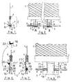
- Figures 1 to 8 show, partially, the pulling strip 1, made either of plastic material or of woven or nonwoven fabric which is intended to be pre-stitched on the back of the cover of a seat to be covered.
- This strip 1 is provided with a device 2 for its attachment to a metal rod or rod 3 embedded in the foam of the seat and / or forming part of its frame.
- the pulling strip 1, with its hooking device 2 allows the fixing and the tensioning at certain points, of the cover on the seat.
- the attachment device 2 is obtained in a single piece by injection molding of plastic material of the polyamide type on the edge of the strip 1.
- the fastening device 2 consists of a longitudinal bar 4, which extends for example over the entire length of the strip 1, and from which s 'extend downwards, one or more independent hooks 5 in the form of a carabiner.
- the number and spacing of the hooks 5, obtained directly by the molding operation, are a function of the pulling and return characteristics desired on the cover of the seat.
- the reinforcing rod 3 is arranged substantially parallel to the longitudinal bar 4 and it is situated practically in the plane of the pulling strip 1; the orientation of the hook (s) 5 is perpendicular to the rod 3.
- Each hook 5 has a base 6 which is intended to come into contact with the lower generatrix of the rod 3 and which serves as a pulling and pulling member on the cap.
- This base 6 is bordered by at least two edges 7 and 8, in the form of shoulders, intended for the lateral retention of the rod 3.
- the edges 7 and 8 are offset between them longitudinally, and one of 'between them, the border 7 in this case, serves as a connection between the base 6 and the bar 4.
- the border 8 consists of an elastic tongue intended to hold the rod 3 in the housing 9 formed by the base 6 and the connecting border 7.
- FIG. 2A schematically shows, front view, a possible embodiment of the one-piece attachment device 2.
- the bar 4 is extended downwards by another vertical border 7 in the form of a beam, the lower end of which extends at an angle towards the front, to form the base 6.
- This base 6 is itself extended upwards, on the other side of the rod 3 relative to the border 7, by two tabs 8 'and 8' ', offset on either side of said border 7.
- FIG. 2B schematically shows, also from the front, a second possible embodiment of the hooking system.
- the longitudinal bar 4 extends downwards by two vertical edges 7 'and 7 '' which are arranged on the same side of the rod 3.
- the two edges 7 'and 7'' are extended forward by a square return defining the base 6, itself extended upwards by a tongue central 8.
- the lateral edges, respectively 7, 8 ', 8' 'and 7', 7 '' and 8, according to the embodiment, are offset longitudinally relative to each other, along the length of the rod, to allow molding by injection of the attachment system on the strips 1.
- a continuous overmolding is carried out step by step, in order to obtain a very long pulling strip, intended to be then split by cutting according to the desired dimensions.
- the strips 1 which equip the cover of a seat generally have lengths of the order of 20 to 40 cm; the bar 4 extends over the entire length of the strip 1 and it comprises a plurality of separate hooks 5 (two to four in general).
- the free edges, in the form of strips or tongues 8, 8 ', 8' ' are advantageously elastic and shaped so, on the one hand, to allow the forced insertion of the rods 3 into their housing (s) ) 9 and, on the other hand, to block the rods in this or these housings.
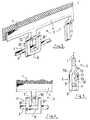
- FIGS 3 to 5 show a first embodiment of the attachment device according to the invention. To simplify the description, the structural elements corresponding to those described in connection with Figures 1 and 2 retain the same references.
- each hook 5 consists of a beam 7 which defines the back of the hook and which extends from the bar 4 to form an assembly having a general T shape.
- the beam 7 is connected to the bar 4 by an inclined pan 10 which shifts it slightly backwards relative to the plane of the strip 1.
- the lower end of the beam 7 is extended at right angles, forward, to form the bottom 6 of the hook.
- This bottom 6 is itself extended upward, by a square return, substantially parallel to the beam 7.
- This return in the example shown, consists of two front tongues 8 'and 8'', mutually parallel and offset laterally on either side of said beam 7.
- the beam 7, bottom 6 and tongue 8, 8 ′ assembly defines a hook arranged transversely with respect to the plane of the strip 1.
- the back of the hook is located behind the plane of said strip 1 and the tongues 8 ′, 8 ′ 'ahead of this plan.
- the tongues are offset laterally with respect to the beam 7 to allow overmolding by injection of the plastic profile 2.
- the end of the tongues 8 'and 8' ' has a re-entrant stop 11 whose upper profile 12 is substantially parallel to the inclined face 10 and whose lower profile 13 extends substantially parallel to the bottom 6.
- the opening 14 of the hook is arranged to obtain easy picking of the rod 3. This opening 14 narrows at the level of the stop 11 to allow locking of the rod 3 in the hook.
- the rod 3 is situated substantially in the plane of the strip 1, thanks to a rearward offset of the beam 7 relative to said plane of the strip 1.
- FIGs 6 to 8 show a second embodiment of the attachment device according to the invention, which is close to the schematic representation of Figure 2B.
- This device consists of a plastic frame 15 ( Figure 8), made in one piece with the bar 4. This frame extends in a plane parallel to that of the strip 1, from the rear face of said bar 4.
- This frame 15 consists of two vertical legs defining the edges 7 'and 7'', connected by a sole 16 disposed parallel to the bar 4, below the level of the rod 3, and from which s 'extends, upwards, the central tongue 8.
- each edge 7, 7 '' has, on its height, a housing 9 in the form of a lying U, open on the side of the strip 8 ( Figures 6 and 7).
- Each housing 9 is delimited by the base 6 forming a bearing surface for the rod 3 and by the connecting edge 7 ', 7'', shaped to define a vertical lateral support 17 forming the bottom of the U 9, extended by a upper return 18 which defines the ceiling of said housing, itself extended by a vertical connecting strip 19 joining the bar 4.
- Each longitudinal housing receives a portion of the rod 3.
- the tongue 8 takes birth from the sole 16, under the base 6. it is shaped to prevent the rod 3 from coming out of the housings 9; its elasticity can in particular make it possible to apply pressure to said rod 3 in order to press the latter against the vertical lateral supports 17.
- the free end of the tongue 8 may advantageously include a ramp 20 which guides the rod 3 and facilitates its introduction into the housing or housings 9 for reception.
- the upper end of the ramp 20 is located at a sufficient distance from the edges 7 ', 7' 'to allow the rod to be hooked by a simple pulling movement on the bar 4.
- This tongue 8 may also have, over its height, a notch 21 more or less marked, making it possible to complete the blocking of the rod 3 in the corresponding housing or housings 9.
- a lug 22 positioned at the entrance to the upper return 18 forming the ceiling of the housing 9; this lug 22 serves as a stop for the rod 3 and maintains it in said housing in the event of pressure on the bar 4.
- An elastic strip 8, disposed between two connecting edges 7 ′, 7 ′′ allows obtaining the homogeneous attachment means, applying no torsional effect to the rod 3.
- the three alternating lateral support zones allow blocking and holding fastening.
- the various embodiments according to the invention allow the strip 1 pre-sewn upside down from a cover for covering car seats, for example, to be hung on a rod 3 forming part of the metal frame of the seat and integrated into a longitudinal well formed in the padding.
- the return band 1 is placed along the length of the well, so that the hooks 5 are arranged perpendicular to the rod 3 and can easily hook it.
- the rod 3 is force-fitted by pressing on the ramps 11 or 20 as appropriate.
- the introduction into the receiving housing 9 can be obtained by making use of the elasticity of the front tab or tabs.
- the positioning of the hooks 5 on the rod 3 makes it possible to create the desired pulling lines.
- the embedding of the rods 3, linked for example to the pushes on the cover during the seat, is avoided, thanks to the particular conformation of the housings 9 and of the support strip (s) 8, 8 ', 8' 'which provide a blocage.
- the rod 3 is disposed on the base 6 of the hook 5, substantially in the plane of the strip 1 and of the bar 4. This arrangement makes it possible to correctly position the device and to distribute the forces well.
- the strip 1 of plastic material; in this case, the entire return band (parts 1, 4 and 5) is advantageously obtained by molding, in one piece; the means for fixing this assembly to the seat cover will then be adapted.
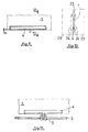
- Figures 9 to 11 relate to the particular assembly method of the attachment device on the return band.
- FIG. 9 shows a portion of fabric 1.
- This fabric can be any, woven or non-woven, made for example of plastic material of the polypropylene or polyamide type.
- the bar 4 used to fix the fabric 1 on the seat frame, not shown, is positioned on the edge of the fabric 1. It can be seen in fact that the bar 4 is arranged in full fabric, that is to say that the canvas overflows all around.
- the plastic material is injected in the middle of the bar, in its median plane, that is to say the plane of the fabric. During the injection, there is a partial melting and an overall softening of your fabric, which promotes welding and provides very high resistance.
- Figure 10 in section, the fabric 1 and the bar 4 which are in the form of two plastic strips arranged on either side of said fabric 1.
- the injection mold is illustrated in thin dashed lines . It consists of two identical blocks 23 in the figure, which have an imprint 24 corresponding to the shape of your bar 4.
- the location of the canvas in the mold this location consists of a very large counterbore 25 produced in each block 23; the depth of this counterbore takes account of the thickness of the fabric 1.
- the fabric 1 is pinched in the mold, around the entire periphery of the imprint of the bar 4. After injection of the plastic material into the mold, the fabric is thus perfectly centered in the thickness of the bar 4.
- the fabric 1 overflows with respect to the bar 4, on the edge, with a value a which is of the order of 1 mm. This overflow can be leveled off afterwards, depending on the aesthetics sought.
- FIG. 11 shows a portion of the pulling or return band produced according to the overmolding method detailed above.
- This pulling strip is in the form of a canvas 1 provided on its edge, with at least one simple strip 4 molded.
- the bar 4 comprises, in a single piece, at least one hook 5 which grips and locks on a rod 3 attached to the cushion or the seat frame, not shown.
Claims (16)
- Befestigungsmittel für ein Spannband (1), insbesondere für ein Spannband eines Sitzüberzugs, an einer im wesentlichen in der Ebene des Bandes angeordneten Stange (3), wobei das Mittel einblockförmig aus einem an dem Spannband (1) festgegossenen Steg (4), der mit einem Einhakungsmittel in Form eines die Stange (3) durch Zug ergreifend angeordneten Karabinerhakens verbunden ist, besteht und das Einhakungsmittel aus mindestens einem Haken (5) besteht, der- ein Fußteil (6), das dazu bestimmt ist, mit der Unterseite der Stange (3)in Kontakt zu stehen, und- mindestens zwei schulterförmige Randteile (7, 8), die zum seitlichen Festhalten der Stange bestimmt sowie auf der einen und der anderen Seite der Stange angeordnet sind, aufweist, dadurch gekennzeichnet, daß die Randteile (7, 8) in Längsrichtung auf der Länge der Stange gegeneinander versetzt sind, und einer von ihnen zur Verbindung zwischen dem Fußteil (6) und dem Steg (4) dient.
- Befestigungsmittel nach Anspruch 1, dadurch gekennzeichnet, daß es zwei auf der selben Seite der Stange (3) angeordnete Verbindungsrandteile(7',7'') und ein freies, auf der anderen Seite zwischen den Verbindungsrandteilen(7',7'')angeordnetes Randteil (8) aufweist.
- Befestigungsmittel nach Anspruch 1, dadurch gekennzeichnet, daß es ein Verbindungsrandteil (7) auf einer Seite der Stange (3) und zwei freie, auf der anderen Seite beiderseits des Verbindungsrandteils (7) angeordnete Randteile (8',8'')aufweist.
- Befestigungsmittel nach einem der Ansprüche 1 bis 3, dadurch gekennzeichnet, daß es einen Haken (5) aufweist, der aus mindestens einem Verbindungsrandteil (7) in Form eines Balkens, wobei der Balken (7) sich im Winkel verlängert, um das Fußteil (6) des Hakens zu bilden, und das Fußteil (6) selbst zu einem zum Balken (7) im wesentlichen parallelen Umkehrteil verlängert ist, und aus mindestens einem freien Randteil (8',8'') in Form einer in Längsrichtung gegenüber dem Balken (7) verschobenen Zunge besteht.
- Befestigungsmittel nach Anspruch 4, dadurch gekennzeichnet, daß das Ende der Zunge oder Zungen (8, 8) einen Anschlag (11) aufweist, der einen Halter für die Beschlagstange (3) bildet.
- Befestigungsmittel nach Anspruch 4 oder 5, dadurch gekennzeichnet, daß es einen gegenüber der Ebene des Rückstellbands (1) nach hinten verschobenen Balken (7) aufweist, so daß die Beschlagstange (3) auf dem Fußteil (6) des Hakens (5) in der Ebene des Bandes (1) angeordnet ist.
- Befestigungsmittel nach einem der Ansprüche 1 bis 3, dadurch gekennzeichnet, daß das freie Randteil oder die freien Randteile (8,8',8'') aus einer zum Festhalten der Stange (3) in dem durch das Fußteil (6) und das Verbindungsrandteil oder die Verbindungsrandteile (7,7',7'') gebildeten Sitz (9) bestimmten, elastischen Lamelle oder Zunge besteht oder bestehen.
- Befestigungsmittel nach Anspruch 7, dadurch gekennzeichnet, daß der Sitz (9) der Stange (3) in Form eines liegenden, nach der elastischen Zunge oder den elastischen Zungen (8,8',8'') hin offenen U's vorliegt, wobei der Sitz (9) durch das Fußteil (6) und das seitliche Verbindungsrandteil oder die seitlichen Verbindungsrandteile (7,7',7'')begrenzt ist, die sich in- einen senkrechten, den tiefsten Teil des Sitzes (9) bildenden Halt (17)- ein oberes, den tiefsten Teil des Sitzes (9) definierendes Umkehrteil (18) und- eine senkrechte, den Steg (4) erreichende Verbindung (19) aufteilen.
- Befestigungsmittel nach Anspruch 7 oder 8, dadurch gekennzeichnet, daß das Ende der Zungen (8,8',8'')eine Rampe (12, 20) zur Führung und Einführung der Stange (3) in ihren Sitz oder ihre Sitze (9) aufweist.
- Befestigungsmittel nach einem der Ansprüche 7 bis 9, dadurch gekennzeichnet, daß das obere Umkehrteil (18) einen als Anschlag der Stange (3) dienenden Vorsprung (22) aufweist.
- Verfahren zur Anbringung durch Festgießen eines Stegs aus Kunststoffmaterial an einem Gewebe , insbesondere für die Ausführung eines Spannbands durch das Spritzgußverfahren, dadurch gekennzeichnet, daß es aus dem Einklemmen des Gewebes (1) in der Form über den gesamten Umfang des Abdrucks des in der Form angeordneten Stegs (4) und dem Einspritzen des Kunststoffmaterials in den Abdruck auf beiden Seiten des Gewebes (1) gleichzeitig besteht.
- Verfahren nach Anspruch 11, dadurch gekennzeichnet, daß es aus dem Einklemmen des Gewebes (1) in der Form auf einem Randteil von mindestens 1 mm besteht.
- Verfahren nach Anspruch 11 oder 12, dadurch gekennzeichnet, daß es aus dem Einspritzen des Kunststoffmaterials in der Mitte des Abdrucks des Stegs (4) innerhalb seiner Mittelebene besteht.
- Verfahren nach einem der Ansprüche 11 bis 13, dadurch gekennzeichnet, daß es aus dem Positionieren des Gewebes (1) in eine Vertiefung (25), die in jedem die Form bildenden Block angeordnet ist, und dem Einklemmen des Gewebes (1) in der Vertiefung (25) vor und während der in geeigneter Weise festgelegten Einspritzung besteht.
- Spannband, das mindestens ein Befestigungsmittel nach einem der Ansprüche 1 bis 10 aufweist und/oder mit dem Verfahren nach einem der Ansprüche 11 bis 14 erhalten ist.
- Haube oder Überzug zum Einhüllen, die oder der mindestens ein Spannband nach Anspruch 15 aufweist.
Applications Claiming Priority (6)
| Application Number | Priority Date | Filing Date | Title |
|---|---|---|---|
| FR9011190 | 1990-09-06 | ||
| FR9011190A FR2666496B1 (fr) | 1990-09-06 | 1990-09-06 | Dispositif d'accrochage d'une bande de rappel notamment pour la coiffe d'un siege et coiffe munie d'un tel dispositif. |
| FR9103542 | 1991-03-19 | ||
| FR9103542A FR2674178B1 (fr) | 1991-03-19 | 1991-03-19 | Procede d'assemblage par surmoulage d'une barrette sur une toile en materiau plastique et produit obtenu du genre bande de tirage pour la confection de sieges. |
| FR9105778 | 1991-05-07 | ||
| FR9105778A FR2676259B1 (fr) | 1991-05-07 | 1991-05-07 | Dispositif d'accrochage d'une bande de tirage en particulier pour la coiffe d'un siege et coiffe munie d'au moins un tel dispositif. |
Publications (2)
| Publication Number | Publication Date |
|---|---|
| EP0474558A1 EP0474558A1 (de) | 1992-03-11 |
| EP0474558B1 true EP0474558B1 (de) | 1995-04-19 |
Family
ID=27252306
Family Applications (1)
| Application Number | Title | Priority Date | Filing Date |
|---|---|---|---|
| EP19910402372 Expired - Lifetime EP0474558B1 (de) | 1990-09-06 | 1991-09-04 | Befestigungsmittel für ein Spannband, insbesondere für ein Spannband eines Sitzüberzuges, Verfahren zur Anbringung des Befestigungsmittels am Gewebe des Spannbandes, und das so hergestellte Spannband |
Country Status (2)
| Country | Link |
|---|---|
| EP (1) | EP0474558B1 (de) |
| DE (1) | DE69109027T2 (de) |
Families Citing this family (5)
| Publication number | Priority date | Publication date | Assignee | Title |
|---|---|---|---|---|
| FR2735960B1 (fr) * | 1995-06-30 | 1997-09-12 | Delahousse Et Fils Sa | Perfectionnements aux bandes de tirage pour le maintien d'une coiffe de coussin |
| DE19929241A1 (de) * | 1999-06-25 | 2000-12-28 | Volkswagen Ag | Anordnung zur Befestigung eines Bezugs auf einem Formteil |
| DE102008009981A1 (de) * | 2008-02-19 | 2009-08-20 | Seatex Ag | Abspanneinrichtung für Sitze |
| FR2970213B1 (fr) * | 2011-01-11 | 2013-01-18 | Cera | Composant de garnissage d'un siege de vehicule automobile |
| DE102011051983B4 (de) * | 2011-07-20 | 2019-11-21 | Oke Group Gmbh | Befestigungselement zur Befestigung eines Sitzbezugs an einem Sitzelement |
Family Cites Families (6)
| Publication number | Priority date | Publication date | Assignee | Title |
|---|---|---|---|---|
| US2335222A (en) * | 1942-07-14 | 1943-11-23 | Harry E Darr | Ornamental plastic fabric |
| US3176057A (en) * | 1963-01-23 | 1965-03-30 | Union Carbide Corp | Molding process |
| US3362302A (en) * | 1965-08-12 | 1968-01-09 | Studley Paper Company Inc | Bag closure |
| FR2596626B1 (fr) * | 1986-04-02 | 1989-07-13 | Peugeot | Siege, notamment pour vehicule automobile |
| JPS6477515A (en) * | 1987-06-18 | 1989-03-23 | Mitsubishi Chem Ind | Manufacture of thin molded item with projected portion |
| FR2636320B1 (fr) * | 1988-09-14 | 1993-12-10 | Nobel Plastiques | Dispositif d'accrochage permettant la realisation de rappels de tissus de recouvrement de sieges |
-
1991
- 1991-09-04 EP EP19910402372 patent/EP0474558B1/de not_active Expired - Lifetime
- 1991-09-04 DE DE1991609027 patent/DE69109027T2/de not_active Expired - Fee Related
Also Published As
| Publication number | Publication date |
|---|---|
| DE69109027D1 (de) | 1995-05-24 |
| EP0474558A1 (de) | 1992-03-11 |
| DE69109027T2 (de) | 1995-12-07 |
Similar Documents
| Publication | Publication Date | Title |
|---|---|---|
| EP1118443B1 (de) | Einsatz sowie Giessformverfahren zum Übergiessen desselben | |
| EP3041652B1 (de) | Haltevorrichtung mit haken | |
| EP0296898A1 (de) | Schuhbefestigungsvorrichtung an einem Fahrradpedal | |
| EP0240388B1 (de) | Sitz, insbesondere für ein Kraftfahrzeug | |
| FR2817714A1 (fr) | Fermeture contact moulee d'un seul tenant | |
| FR2466330A1 (fr) | Procede de surmoulage de bandes femelles pour systemes a crochets sur des matelassures en mousse de polyurethane | |
| EP0474558B1 (de) | Befestigungsmittel für ein Spannband, insbesondere für ein Spannband eines Sitzüberzuges, Verfahren zur Anbringung des Befestigungsmittels am Gewebe des Spannbandes, und das so hergestellte Spannband | |
| EP0433100B1 (de) | Vorrichtung zum Befestigen eines Überzuges eines Kraftzeugsitzes | |
| FR2735960A1 (fr) | Perfectionnements aux bandes de tirage pour le maintien d'une coiffe de coussin | |
| WO2011089334A1 (fr) | Assemblage d'un surmoule a crochets et d'un moule comportant un piedestal | |
| FR2761863A1 (fr) | Ruban auto-agrippant pour siege, son procede de fabrication, procede de fabrication d'un siege comportant un tel ruban et siege ainsi obtenu | |
| EP2384925B1 (de) | Rückenlehnenkörper eines im Blasverfahren hergestellten Kunststoff-Sitzes, der mit einer Verankerungsvorrichtung für die gesicherte Fixierung eines Kindersitzes ausgestattet ist | |
| EP0252783B1 (de) | Vorrichtung zum Befestigen eines Überzuges eines Kraftfahrzeugsitzes | |
| EP2525688B1 (de) | Anordnung eines geformten objekts mit einer vielzahl umgespritzter hakenelemente und mit einer abdeckung | |
| FR2917023A1 (fr) | Structure d'assise pour siege de vehicule et siege de vehicule comportant une telle structure | |
| FR2624355A1 (fr) | Piece monobloc destinee a la confection d'une chaussure | |
| FR2666496A1 (fr) | Dispositif d'accrochage d'une bande de rappel notamment pour la coiffe d'un siege et coiffe munie d'un tel dispositif. | |
| FR2939085A1 (fr) | Systeme d'accrochage d'une coiffe pour sieges de vehicule automobile | |
| EP0008986B1 (de) | Verfahren und Vorrichtung zum Beziehen eines Polsters mit einem Bezug | |
| FR2676259A1 (fr) | Dispositif d'accrochage d'une bande de tirage en particulier pour la coiffe d'un siege et coiffe munie d'au moins un tel dispositif. | |
| FR2780355A1 (fr) | Appui-tete de type sensiblement annulaire, notamment pour siege de vehicule automobile | |
| EP2961631B1 (de) | Kraftfahrzeugsitzelement, sitz mit solch einem element, fahrzeug mit solch einem sitz und verfahren zur montage solch eines elements | |
| FR3018234A1 (fr) | Armature d'assise de siege de vehicule automobile integrant des moyens de retenue de la garniture | |
| FR2750372A1 (fr) | Siege pour enfant a harnais de securite reglable | |
| FR2891217A1 (fr) | Dossier de siege de vehicule automobile comportant un panneau arriere d'habillage. |
Legal Events
| Date | Code | Title | Description |
|---|---|---|---|
| PUAI | Public reference made under article 153(3) epc to a published international application that has entered the european phase |
Free format text: ORIGINAL CODE: 0009012 |
|
| AK | Designated contracting states |
Kind code of ref document: A1 Designated state(s): BE DE ES FR GB IT SE |
|
| 17P | Request for examination filed |
Effective date: 19920907 |
|
| 17Q | First examination report despatched |
Effective date: 19930223 |
|
| RAP3 | Party data changed (applicant data changed or rights of an application transferred) |
Owner name: SA DELAHOUSSE ET FILS |
|
| RBV | Designated contracting states (corrected) |
Designated state(s): DE FR |
|
| GRAA | (expected) grant |
Free format text: ORIGINAL CODE: 0009210 |
|
| RBV | Designated contracting states (corrected) |
Designated state(s): BE DE ES FR GB IT SE |
|
| AK | Designated contracting states |
Kind code of ref document: B1 Designated state(s): BE DE ES FR GB IT SE |
|
| PG25 | Lapsed in a contracting state [announced via postgrant information from national office to epo] |
Ref country code: IT Free format text: LAPSE BECAUSE OF FAILURE TO SUBMIT A TRANSLATION OF THE DESCRIPTION OR TO PAY THE FEE WITHIN THE PRE;WARNING: LAPSES OF ITALIAN PATENTS WITH EFFECTIVE DATE BEFORE 2007 MAY HAVE OCCURRED AT ANY TIME BEFORE 2007. THE CORRECT EFFECTIVE DATE MAY BE DIFFERENT FROM THE ONE RECORDED.SCRIBED TIME-LIMIT Effective date: 19950419 Ref country code: ES Free format text: THE PATENT HAS BEEN ANNULLED BY A DECISION OF A NATIONAL AUTHORITY Effective date: 19950419 Ref country code: GB Effective date: 19950419 |
|
| REF | Corresponds to: |
Ref document number: 69109027 Country of ref document: DE Date of ref document: 19950524 |
|
| PG25 | Lapsed in a contracting state [announced via postgrant information from national office to epo] |
Ref country code: SE Effective date: 19950719 |
|
| PG25 | Lapsed in a contracting state [announced via postgrant information from national office to epo] |
Ref country code: BE Effective date: 19950930 |
|
| GBV | Gb: ep patent (uk) treated as always having been void in accordance with gb section 77(7)/1977 [no translation filed] |
Effective date: 19950419 |
|
| PLBE | No opposition filed within time limit |
Free format text: ORIGINAL CODE: 0009261 |
|
| STAA | Information on the status of an ep patent application or granted ep patent |
Free format text: STATUS: NO OPPOSITION FILED WITHIN TIME LIMIT |
|
| BERE | Be: lapsed |
Owner name: S.A. DELAHOUSSE ET FILS Effective date: 19950930 |
|
| 26N | No opposition filed | ||
| REG | Reference to a national code |
Ref country code: FR Ref legal event code: CD Ref country code: FR Ref legal event code: TP |
|
| PGFP | Annual fee paid to national office [announced via postgrant information from national office to epo] |
Ref country code: FR Payment date: 20010829 Year of fee payment: 11 |
|
| PGFP | Annual fee paid to national office [announced via postgrant information from national office to epo] |
Ref country code: DE Payment date: 20011123 Year of fee payment: 11 |
|
| PG25 | Lapsed in a contracting state [announced via postgrant information from national office to epo] |
Ref country code: DE Free format text: LAPSE BECAUSE OF NON-PAYMENT OF DUE FEES Effective date: 20030401 |
|
| PG25 | Lapsed in a contracting state [announced via postgrant information from national office to epo] |
Ref country code: FR Free format text: LAPSE BECAUSE OF NON-PAYMENT OF DUE FEES Effective date: 20030603 |
|
| REG | Reference to a national code |
Ref country code: FR Ref legal event code: ST |