EP0474558B1 - Fastening device for a tightening band, in particular for a tightening band of a seat cover, method of the assembly of the fastening device on the cloth of the tightening band and tightening band obtained - Google Patents
Fastening device for a tightening band, in particular for a tightening band of a seat cover, method of the assembly of the fastening device on the cloth of the tightening band and tightening band obtained Download PDFInfo
- Publication number
- EP0474558B1 EP0474558B1 EP19910402372 EP91402372A EP0474558B1 EP 0474558 B1 EP0474558 B1 EP 0474558B1 EP 19910402372 EP19910402372 EP 19910402372 EP 91402372 A EP91402372 A EP 91402372A EP 0474558 B1 EP0474558 B1 EP 0474558B1
- Authority
- EP
- European Patent Office
- Prior art keywords
- rod
- fastening device
- bar
- tightening band
- cloth
- Prior art date
- Legal status (The legal status is an assumption and is not a legal conclusion. Google has not performed a legal analysis and makes no representation as to the accuracy of the status listed.)
- Expired - Lifetime
Links
Images
Classifications
-
- B—PERFORMING OPERATIONS; TRANSPORTING
- B60—VEHICLES IN GENERAL
- B60N—SEATS SPECIALLY ADAPTED FOR VEHICLES; VEHICLE PASSENGER ACCOMMODATION NOT OTHERWISE PROVIDED FOR
- B60N2/00—Seats specially adapted for vehicles; Arrangement or mounting of seats in vehicles
- B60N2/58—Seat coverings
- B60N2/5816—Seat coverings attachments thereof
- B60N2/5825—Seat coverings attachments thereof by hooks, staples, clips, snap fasteners or the like
-
- B—PERFORMING OPERATIONS; TRANSPORTING
- B29—WORKING OF PLASTICS; WORKING OF SUBSTANCES IN A PLASTIC STATE IN GENERAL
- B29C—SHAPING OR JOINING OF PLASTICS; SHAPING OF MATERIAL IN A PLASTIC STATE, NOT OTHERWISE PROVIDED FOR; AFTER-TREATMENT OF THE SHAPED PRODUCTS, e.g. REPAIRING
- B29C45/00—Injection moulding, i.e. forcing the required volume of moulding material through a nozzle into a closed mould; Apparatus therefor
- B29C45/14—Injection moulding, i.e. forcing the required volume of moulding material through a nozzle into a closed mould; Apparatus therefor incorporating preformed parts or layers, e.g. injection moulding around inserts or for coating articles
- B29C45/14336—Coating a portion of the article, e.g. the edge of the article
-
- B—PERFORMING OPERATIONS; TRANSPORTING
- B29—WORKING OF PLASTICS; WORKING OF SUBSTANCES IN A PLASTIC STATE IN GENERAL
- B29L—INDEXING SCHEME ASSOCIATED WITH SUBCLASS B29C, RELATING TO PARTICULAR ARTICLES
- B29L2031/00—Other particular articles
- B29L2031/727—Fastening elements
Definitions
- the present invention relates to a device for attaching a pulling strip intended in particular to equip the cover of a seat; it also relates to a method of assembling such a device on a canvas as well as the pulling strip obtained.
- the seat and the backrest of seats consist of a metal frame around which is placed a padding, for example made of synthetic foam.
- the padding is covered with a cover forming a cover which comprises, on its external surface, a whole set of recessed or imprinted parts, arranged according to the comfort and the desired aesthetics.
- These imprints are obtained by means of reminders from the cover towards the inside of the seat. These reminders are generally produced by strips on the internal face of the cover and provided with attachment means, either in the padding, or on rods or rods embedded in the foam or forming part of the seat carcass.
- the device for attaching the pre-sewn pulling strip to the back of the cap consists of a plastic bar which extends over the entire length of the strip and which is joined on its edge by welding and in particular by means of molding-coextrusion techniques.
- the plastic bar is extended by a one-piece hooking means which is obtained over the entire length of said bar, in connection with the embodiment by extrusion. This longitudinal attachment means is then cut to form a succession of staples.
- the pulling strip can then be secured on the back of a cap and come to hang, from above, by means of its snap hooks in the shape of a carabiner, on a rod of the seat frame, placed under said strip. , substantially in the same plane. To obtain the hooking, you have to press the clip on the rod.
- the device Given its structural characteristics, the device can only be obtained by techniques of the spinning or co-extrusion type. An additional cutting operation is necessary to obtain spaced attachment means and this operation complicates the production of the device and makes it more expensive.
- Document EP-A-0 240 388 describes another type of system consisting of a longitudinal strip overmolded on the edge of the strip and from which extend a plurality of hooking means in the form of sea anchors.
- These attachment systems are obtained in one piece with the bar, by means of an injection molding technique.
- the attachment is carried out on a polyamide fabric with large meshes and no longer on a reinforcing rod arranged parallel to the return band. To obtain the attachment, you must press on each anchor; there are risks of dropping out on this system.
- the object of the present invention relates to a device for hooking a return band intended to be secured to conventional carcasses of seats, that is to say on carcasses equipped with rods or reinforcing rods arranged substantially parallel to the plane of said strip.
- the object of the invention is to simplify the manufacture of these pull or recall strips.
- Another object of the invention is to make the hanging operation easier, to also make it faster and safer, and to allow disassembly of the pulling strip.
- the invention also provides greater security and a guarantee against untimely, accidental stalls.
- the longitudinal offset of the lateral edges allows the use of injection molding techniques, on the edge of the strip to obtain hooking means which extend substantially in a plane perpendicular to the plane of said strip and to the longitudinal plane of the molded bar.
- the device comprises two connecting edges arranged on the same side of the rod and a free edge, on the other side, disposed between said connecting edges.
- the device comprises a connecting edge on one side of the rod and two free edges, on the other side, arranged on either side of said connecting edge.
- the device comprises a hook consisting of at least one connecting edge in the form of a beam, which beam extends at right angles to form the base of said hook.
- This base is itself extended by a return substantially parallel to said beam and consisting of at least one free edge in the form of a tongue offset longitudinally with respect to said beam.
- the end of the tab (s) may include a stop forming a retainer for the reinforcing rod; the beam can advantageously be offset rearward, relative to the plane of the return band, so as to arrange the reinforcing rod on the base of the hook in the plane of said band.
- the free edge or edges consist of a resilient strip or tab intended to hold the rod in the housing formed by the base and the connecting edge.
- the housing of the rod is then in the form of a lying U, open on the elastic tongue.
- This housing is delimited by the base and the lateral connecting edge, which decomposes into a lateral support.
- vertical forming the bottom of the U, in an upper return defining the ceiling of the housing and in a vertical connection joining the molded bar.
- the ceiling may include a lug arranged at the entrance, which lug serves as a means of retaining the rod in the housing to prevent its untimely withdrawal when pressure is exerted on the bar.
- the end of the tongue or tongues comprises a ramp for guiding and introducing the rod into its housing or housings; the tab (s) also preferably include a locking notch for the reinforcing rod which is forcibly embedded in the U-shaped housing.
- the tab or tabs originate under the base which serves to support the rod; it is thus possible to obtain an excellent elasticity of the tongue (s) to achieve effective blocking of the rod, and its possible disassembly by action on said tongue.
- the invention also relates to a method of assembling a bar of plastic material on a canvas. This process is always linked to the concern to allow the use of injection molding techniques to obtain a simple and quality attachment device. Of course, this process is not limited exclusively to the production and application of pulling strips for the manufacture of seats for motor vehicles.
- the fabric which is used to make these return bands is by nature as flexible as possible for reasons of comfort and it is preferably made of non-woven material for economic reasons.
- the invention provides a method of assembling by molding a bar on the edge of a fabric, which has the advantage of avoiding any deformation of the fabric and which makes it possible to perfectly center said fabric in the thickness of the bar.
- This method also has the advantage of considerably reducing the tolerances for positioning the fabric in the mold. This allows in particular a significant saving of time during this positioning.
- the method of assembling by overmolding a bar of plastic material on a canvas consists in pinching the canvas in the mold, around the entire periphery of the imprint of the bar arranged in said mold, and injecting the plastic material into the imprint, on either side of the canvas, simultaneously.
- the canvas is pinched on a border of at least 1 mm, all around the imprint; it is preferably housed in a counterbore arranged in each of the blocks constituting the mold.
- the injection of the plastic material into the impression is preferably carried out in the middle of the impression of the bar, in the median plane corresponding to the plane of the fabric.
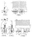
- Figures 1 to 8 show, partially, the pulling strip 1, made either of plastic material or of woven or nonwoven fabric which is intended to be pre-stitched on the back of the cover of a seat to be covered.
- This strip 1 is provided with a device 2 for its attachment to a metal rod or rod 3 embedded in the foam of the seat and / or forming part of its frame.
- the pulling strip 1, with its hooking device 2 allows the fixing and the tensioning at certain points, of the cover on the seat.
- the attachment device 2 is obtained in a single piece by injection molding of plastic material of the polyamide type on the edge of the strip 1.
- the fastening device 2 consists of a longitudinal bar 4, which extends for example over the entire length of the strip 1, and from which s 'extend downwards, one or more independent hooks 5 in the form of a carabiner.
- the number and spacing of the hooks 5, obtained directly by the molding operation, are a function of the pulling and return characteristics desired on the cover of the seat.
- the reinforcing rod 3 is arranged substantially parallel to the longitudinal bar 4 and it is situated practically in the plane of the pulling strip 1; the orientation of the hook (s) 5 is perpendicular to the rod 3.
- Each hook 5 has a base 6 which is intended to come into contact with the lower generatrix of the rod 3 and which serves as a pulling and pulling member on the cap.
- This base 6 is bordered by at least two edges 7 and 8, in the form of shoulders, intended for the lateral retention of the rod 3.
- the edges 7 and 8 are offset between them longitudinally, and one of 'between them, the border 7 in this case, serves as a connection between the base 6 and the bar 4.
- the border 8 consists of an elastic tongue intended to hold the rod 3 in the housing 9 formed by the base 6 and the connecting border 7.
- FIG. 2A schematically shows, front view, a possible embodiment of the one-piece attachment device 2.
- the bar 4 is extended downwards by another vertical border 7 in the form of a beam, the lower end of which extends at an angle towards the front, to form the base 6.
- This base 6 is itself extended upwards, on the other side of the rod 3 relative to the border 7, by two tabs 8 'and 8' ', offset on either side of said border 7.
- FIG. 2B schematically shows, also from the front, a second possible embodiment of the hooking system.
- the longitudinal bar 4 extends downwards by two vertical edges 7 'and 7 '' which are arranged on the same side of the rod 3.
- the two edges 7 'and 7'' are extended forward by a square return defining the base 6, itself extended upwards by a tongue central 8.
- the lateral edges, respectively 7, 8 ', 8' 'and 7', 7 '' and 8, according to the embodiment, are offset longitudinally relative to each other, along the length of the rod, to allow molding by injection of the attachment system on the strips 1.
- a continuous overmolding is carried out step by step, in order to obtain a very long pulling strip, intended to be then split by cutting according to the desired dimensions.
- the strips 1 which equip the cover of a seat generally have lengths of the order of 20 to 40 cm; the bar 4 extends over the entire length of the strip 1 and it comprises a plurality of separate hooks 5 (two to four in general).
- the free edges, in the form of strips or tongues 8, 8 ', 8' ' are advantageously elastic and shaped so, on the one hand, to allow the forced insertion of the rods 3 into their housing (s) ) 9 and, on the other hand, to block the rods in this or these housings.
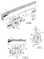
- FIGS 3 to 5 show a first embodiment of the attachment device according to the invention. To simplify the description, the structural elements corresponding to those described in connection with Figures 1 and 2 retain the same references.
- each hook 5 consists of a beam 7 which defines the back of the hook and which extends from the bar 4 to form an assembly having a general T shape.
- the beam 7 is connected to the bar 4 by an inclined pan 10 which shifts it slightly backwards relative to the plane of the strip 1.
- the lower end of the beam 7 is extended at right angles, forward, to form the bottom 6 of the hook.
- This bottom 6 is itself extended upward, by a square return, substantially parallel to the beam 7.
- This return in the example shown, consists of two front tongues 8 'and 8'', mutually parallel and offset laterally on either side of said beam 7.
- the beam 7, bottom 6 and tongue 8, 8 ′ assembly defines a hook arranged transversely with respect to the plane of the strip 1.
- the back of the hook is located behind the plane of said strip 1 and the tongues 8 ′, 8 ′ 'ahead of this plan.
- the tongues are offset laterally with respect to the beam 7 to allow overmolding by injection of the plastic profile 2.
- the end of the tongues 8 'and 8' ' has a re-entrant stop 11 whose upper profile 12 is substantially parallel to the inclined face 10 and whose lower profile 13 extends substantially parallel to the bottom 6.
- the opening 14 of the hook is arranged to obtain easy picking of the rod 3. This opening 14 narrows at the level of the stop 11 to allow locking of the rod 3 in the hook.
- the rod 3 is situated substantially in the plane of the strip 1, thanks to a rearward offset of the beam 7 relative to said plane of the strip 1.
- FIGs 6 to 8 show a second embodiment of the attachment device according to the invention, which is close to the schematic representation of Figure 2B.
- This device consists of a plastic frame 15 ( Figure 8), made in one piece with the bar 4. This frame extends in a plane parallel to that of the strip 1, from the rear face of said bar 4.
- This frame 15 consists of two vertical legs defining the edges 7 'and 7'', connected by a sole 16 disposed parallel to the bar 4, below the level of the rod 3, and from which s 'extends, upwards, the central tongue 8.
- each edge 7, 7 '' has, on its height, a housing 9 in the form of a lying U, open on the side of the strip 8 ( Figures 6 and 7).
- Each housing 9 is delimited by the base 6 forming a bearing surface for the rod 3 and by the connecting edge 7 ', 7'', shaped to define a vertical lateral support 17 forming the bottom of the U 9, extended by a upper return 18 which defines the ceiling of said housing, itself extended by a vertical connecting strip 19 joining the bar 4.
- Each longitudinal housing receives a portion of the rod 3.
- the tongue 8 takes birth from the sole 16, under the base 6. it is shaped to prevent the rod 3 from coming out of the housings 9; its elasticity can in particular make it possible to apply pressure to said rod 3 in order to press the latter against the vertical lateral supports 17.
- the free end of the tongue 8 may advantageously include a ramp 20 which guides the rod 3 and facilitates its introduction into the housing or housings 9 for reception.
- the upper end of the ramp 20 is located at a sufficient distance from the edges 7 ', 7' 'to allow the rod to be hooked by a simple pulling movement on the bar 4.
- This tongue 8 may also have, over its height, a notch 21 more or less marked, making it possible to complete the blocking of the rod 3 in the corresponding housing or housings 9.
- a lug 22 positioned at the entrance to the upper return 18 forming the ceiling of the housing 9; this lug 22 serves as a stop for the rod 3 and maintains it in said housing in the event of pressure on the bar 4.
- An elastic strip 8, disposed between two connecting edges 7 ′, 7 ′′ allows obtaining the homogeneous attachment means, applying no torsional effect to the rod 3.
- the three alternating lateral support zones allow blocking and holding fastening.
- the various embodiments according to the invention allow the strip 1 pre-sewn upside down from a cover for covering car seats, for example, to be hung on a rod 3 forming part of the metal frame of the seat and integrated into a longitudinal well formed in the padding.
- the return band 1 is placed along the length of the well, so that the hooks 5 are arranged perpendicular to the rod 3 and can easily hook it.
- the rod 3 is force-fitted by pressing on the ramps 11 or 20 as appropriate.
- the introduction into the receiving housing 9 can be obtained by making use of the elasticity of the front tab or tabs.
- the positioning of the hooks 5 on the rod 3 makes it possible to create the desired pulling lines.
- the embedding of the rods 3, linked for example to the pushes on the cover during the seat, is avoided, thanks to the particular conformation of the housings 9 and of the support strip (s) 8, 8 ', 8' 'which provide a blocage.
- the rod 3 is disposed on the base 6 of the hook 5, substantially in the plane of the strip 1 and of the bar 4. This arrangement makes it possible to correctly position the device and to distribute the forces well.
- the strip 1 of plastic material; in this case, the entire return band (parts 1, 4 and 5) is advantageously obtained by molding, in one piece; the means for fixing this assembly to the seat cover will then be adapted.
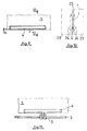
- Figures 9 to 11 relate to the particular assembly method of the attachment device on the return band.
- FIG. 9 shows a portion of fabric 1.
- This fabric can be any, woven or non-woven, made for example of plastic material of the polypropylene or polyamide type.
- the bar 4 used to fix the fabric 1 on the seat frame, not shown, is positioned on the edge of the fabric 1. It can be seen in fact that the bar 4 is arranged in full fabric, that is to say that the canvas overflows all around.
- the plastic material is injected in the middle of the bar, in its median plane, that is to say the plane of the fabric. During the injection, there is a partial melting and an overall softening of your fabric, which promotes welding and provides very high resistance.
- Figure 10 in section, the fabric 1 and the bar 4 which are in the form of two plastic strips arranged on either side of said fabric 1.
- the injection mold is illustrated in thin dashed lines . It consists of two identical blocks 23 in the figure, which have an imprint 24 corresponding to the shape of your bar 4.
- the location of the canvas in the mold this location consists of a very large counterbore 25 produced in each block 23; the depth of this counterbore takes account of the thickness of the fabric 1.
- the fabric 1 is pinched in the mold, around the entire periphery of the imprint of the bar 4. After injection of the plastic material into the mold, the fabric is thus perfectly centered in the thickness of the bar 4.
- the fabric 1 overflows with respect to the bar 4, on the edge, with a value a which is of the order of 1 mm. This overflow can be leveled off afterwards, depending on the aesthetics sought.
- FIG. 11 shows a portion of the pulling or return band produced according to the overmolding method detailed above.
- This pulling strip is in the form of a canvas 1 provided on its edge, with at least one simple strip 4 molded.
- the bar 4 comprises, in a single piece, at least one hook 5 which grips and locks on a rod 3 attached to the cushion or the seat frame, not shown.
Description
La présente invention concerne un dispositif d'accrochage d'une bande de tirage destinée en particulier à équiper la coiffe d'un siège ; elle concerne également un procédé d'assemblage d'un tel dispositif sur une toile ainsi que la bande de tirage obtenue.The present invention relates to a device for attaching a pulling strip intended in particular to equip the cover of a seat; it also relates to a method of assembling such a device on a canvas as well as the pulling strip obtained.
L'assise et le dossier de sièges, notamment des sièges automobiles, sont constitués d'une armature métallique autour de laquelle est disposée une matelassure, par exemple constituée de mousse synthétique. La matelassure est recouverte d'une coiffe formant housse qui comporte, sur sa surface externe, tout un ensemble de parties en creux ou empreintes, disposées en fonction du confort et de l'esthétique désirée. Ces empreintes sont obtenues au moyen de rappels de la coiffe vers l'intérieur du siège. Ces rappels sont en règle générale réalisés par des bandes sur la face interne de la coiffe et munis de moyens d'accrochage, soit dans la matelassure, soit sur des tiges ou des tringles noyées dans la mousse ou faisant partie de la carcasse du siège.The seat and the backrest of seats, in particular of automobile seats, consist of a metal frame around which is placed a padding, for example made of synthetic foam. The padding is covered with a cover forming a cover which comprises, on its external surface, a whole set of recessed or imprinted parts, arranged according to the comfort and the desired aesthetics. These imprints are obtained by means of reminders from the cover towards the inside of the seat. These reminders are generally produced by strips on the internal face of the cover and provided with attachment means, either in the padding, or on rods or rods embedded in the foam or forming part of the seat carcass.
Tel que décrit dans le document EP-A-0 359 643 qui représente le préambule des revendications indépendantes 1, 11, 15 et 16, le dispositif d'accrochage de la bande de tirage précousue sur l'envers de la coiffe, consiste en une barrette plastique qui s'étend sur toute la longueur de la bande et qui est solidarisée sur sa bordure par soudage et notamment au moyen de techniques de moulage-coextrusion. La barrette plastique se prolonge par un moyen d'accrochage monobloc qui est obtenu sur toute la longueur de ladite barrette, en liaison avec le mode de réalisation par extrusion. Ce moyen d'accrochage longitudinal est ensuite découpé pour former une succession d'agrafes. La bande de tirage peut alors être solidarisée sur l'envers d'une coiffe et venir s'accrocher, par le dessus, au moyen de ses agrafes en forme de mousqueton, sur une tringle de l'armature du siège, disposée sous ladite bande, sensiblement dans le même plan. Pour obtenir l'accrochage, il faut presser l'agrafe sur la tringle.As described in document EP-A-0 359 643 which represents the preamble of the
Compte tenu de ses caractéristiques structurelles, le dispositif ne peut être obtenu que par des techniques du type filage ou co-extrusion. Une opération complémentaire de découpe est nécessaire pour obtenir des moyens d'accrochage espacés et cette opération complique la réalisation du dispositif et la rend plus onéreuse.Given its structural characteristics, the device can only be obtained by techniques of the spinning or co-extrusion type. An additional cutting operation is necessary to obtain spaced attachment means and this operation complicates the production of the device and makes it more expensive.
On connaît d'autres systèmes d'amarrage sur une tige d'armature, au moyen d'agrafes du type "nez de porc" solidarisées à la bande de tissu au moyen de couture ou d'une bordure soudée. Les agrafes s'étendent perpendiculairement au plan de la bande et permettent l'accrochage sur des tiges d'armatures parallèles à cette bande. Ce type de système est relativement complexe à mettre en oeuvre ; il nécessite de nombreuses opérations, à la fabrication ainsi qu'au montage sur le siège.Other mooring systems are known on a reinforcing rod, by means of staples of the "pig nose" type secured to the strip of fabric by means of sewing or a welded edge. The staples extend perpendicular to the plane of the strip and allow the attachment to reinforcing rods parallel to this strip. This type of system is relatively complex to implement; it requires numerous operations, both in manufacturing and in mounting on the seat.
Le document EP-A-0 240 388 décrit un autre type de système constitué d'une barrette longitudinale surmoulée sur la bordure de la bande et à partir de laquelle s'étendent une pluralité de moyens d'accrochage en forme d'ancres marines. Ces systèmes d'accrochage sont obtenus d'un seul tenant avec la barrette, au moyen d'une technique de surmoulage par injection. L'accrochage s'effectue sur une toile polyamide à grosses mailles et non plus sur une tringle d'armature disposée parallèlement à la bande de rappel. Pour obtenir l'accrochage, il faut appuyer sur chaque ancre ; des risques de décrochage existent sur ce système.Document EP-A-0 240 388 describes another type of system consisting of a longitudinal strip overmolded on the edge of the strip and from which extend a plurality of hooking means in the form of sea anchors. These attachment systems are obtained in one piece with the bar, by means of an injection molding technique. The attachment is carried out on a polyamide fabric with large meshes and no longer on a reinforcing rod arranged parallel to the return band. To obtain the attachment, you must press on each anchor; there are risks of dropping out on this system.
L'objet de la présente invention concerne un dispositif d'accrochage d'une bande de rappel destinée à être solidarisée sur des carcasses classiques de sièges, c'est-à-dire sur des carcasses équipées de tringles ou de tiges d'armature disposées sensiblement parallèlement au plan de ladite bande. Le but de l'invention est de simplifier la fabrication de ces bandes de tirage ou de rappel. Un autre but de l'invention est de rendre plus facile l'opération d'accrochage, de la rendre également plus rapide et plus sûre, et de permettre un démontage de la bande de tirage.The object of the present invention relates to a device for hooking a return band intended to be secured to conventional carcasses of seats, that is to say on carcasses equipped with rods or reinforcing rods arranged substantially parallel to the plane of said strip. The object of the invention is to simplify the manufacture of these pull or recall strips. Another object of the invention is to make the hanging operation easier, to also make it faster and safer, and to allow disassembly of the pulling strip.
L'invention procure également une plus grande sécurité et une garantie contre les décrochages intempestifs, accidentels.The invention also provides greater security and a guarantee against untimely, accidental stalls.
Selon l'invention, le dispositif est constitué, de façon monobloc, d'une barrette surmoulée sur la bordure de la bande, associée à un moyen de crochetage du type mousqueton. Ce dernier est disposé de façon à agripper la tige et à se verrouiller par traction, et il est constitué d'au moins un crochet comportant :
- une embase destinée à être en contact avec la génératrice dé la tige qui est à l'opposé de la bande de tirage,
- au moins deux bordures en forme d'épaulements, destinées au maintien latéral de la tige ; ces bordures sont décalées entre elles, longitudinalement sur la longueur de la tige ; l'une desdites bordures sert de liaison entre l'embase et la barrette.
- a base intended to be in contact with the generator of the rod which is opposite the pulling strip,
- at least two edges in the form of shoulders, intended for lateral support of the rod; these edges are offset between them, longitudinally along the length of the rod; one of said edges serves as a connection between the base and the bar.
Le décalage longitudinal des bordures latérales permet l'utilisation de techniques de surmoulage par injection, sur la bordure de la bande pour obtenir des moyens d'accrochage qui s'étendent sensiblement dans un plan perpendiculaire au plan de ladite bande et au plan longitudinal de la barrette surmoulée.The longitudinal offset of the lateral edges allows the use of injection molding techniques, on the edge of the strip to obtain hooking means which extend substantially in a plane perpendicular to the plane of said strip and to the longitudinal plane of the molded bar.
Selon un premier mode de réalisation, le dispositif comporte deux bordures de liaison disposées d'un même côté de la tige et une bordure libre, de l'autre côté, disposée entre lesdites bordures de liaison.According to a first embodiment, the device comprises two connecting edges arranged on the same side of the rod and a free edge, on the other side, disposed between said connecting edges.
Selon un second mode de réalisation, le dispositif comporte une bordure de liaison d'un côté de la tige et deux bordures libres, de l'autre côté, disposées de part et d'autre de ladite bordure de liaison.According to a second embodiment, the device comprises a connecting edge on one side of the rod and two free edges, on the other side, arranged on either side of said connecting edge.
Dans une forme de réalisation particulière, le dispositif comporte un crochet constitué d'au moins une bordure de liaison en forme de poutre, laquelle poutre se prolonge en équerre pour former l'embase dudit crochet. Cette embase est elle-même prolongée par un retour sensiblement parallèle à ladite poutre et constituée d'au moins une bordure libre en forme de languette décalée longitudinalement par rapport à ladite poutre.In a particular embodiment, the device comprises a hook consisting of at least one connecting edge in the form of a beam, which beam extends at right angles to form the base of said hook. This base is itself extended by a return substantially parallel to said beam and consisting of at least one free edge in the form of a tongue offset longitudinally with respect to said beam.
L'extrémité de la ou des languettes peut comporter une butée formant arrêtoir pour la tige d'armature ; la poutre peut avantageusement être décalée vers l'arrière, par rapport au plan de la bande de rappel, de façon à disposer la tige d'armature sur l'embase du crochet dans le plan de ladite bande.The end of the tab (s) may include a stop forming a retainer for the reinforcing rod; the beam can advantageously be offset rearward, relative to the plane of the return band, so as to arrange the reinforcing rod on the base of the hook in the plane of said band.
Selon une autre forme de réalisation, la ou les bordures libres consistent en une lamelle ou languette élastique destinée au maintien de la tige dans le logement formé par l'embase et la bordure de liaison.According to another embodiment, the free edge or edges consist of a resilient strip or tab intended to hold the rod in the housing formed by the base and the connecting edge.
Selon une disposition préférentielle, le logement de la tige est alors en forme de U couché, ouvert sur la languette élastique. Ce logement est délimilé par l' embase et la bordure latérale de liaison, laquelle se décompose en un appui latéral vertical formant le fond du U, en un retour supérieur définissant le plafond du logement et en une liaison verticale rejoignant la barrette surmoulée. Le plafond peut comporter un ergot disposé à l'entrée, lequel ergot sert de moyen de retenue de la tige dans le logement pour éviter son retrait intempestif lorsqu'une pression s'exerce sur la barrette.According to a preferred arrangement, the housing of the rod is then in the form of a lying U, open on the elastic tongue. This housing is delimited by the base and the lateral connecting edge, which decomposes into a lateral support. vertical forming the bottom of the U, in an upper return defining the ceiling of the housing and in a vertical connection joining the molded bar. The ceiling may include a lug arranged at the entrance, which lug serves as a means of retaining the rod in the housing to prevent its untimely withdrawal when pressure is exerted on the bar.
Selon une autre caractéristique avantageuse , l'extrémité de la ou des languettes comporte une rampe de guidage et d'introduction de la tige dans son ou ses logements ; la ou les languetttes comportent également de préférence une échancrure de blocage pour la tige d'armature qui est encastrée à force dans le logement en forme de U.According to another advantageous characteristic, the end of the tongue or tongues comprises a ramp for guiding and introducing the rod into its housing or housings; the tab (s) also preferably include a locking notch for the reinforcing rod which is forcibly embedded in the U-shaped housing.
Selon une autre caractéristique, la ou les languettes prennent naissance sous l'embase qui sert d'appui à la tige ; il est ainsi possible d'obtenir une excellente élasticité de la ou des languettes pour réaliser un blocage efficace de la tige, et son démontage éventuel par action sur ladite languette.According to another characteristic, the tab or tabs originate under the base which serves to support the rod; it is thus possible to obtain an excellent elasticity of the tongue (s) to achieve effective blocking of the rod, and its possible disassembly by action on said tongue.
L'invention concerne également un procédé d'assemblage d'une barrette en matériau plastique sur une toile. Ce procédé est toujours lié au souci de permettre l'utilisation de techniques de moulage-injection pour l'obtention d'un dispositif d'accrochage simple et de qualité. Bien entendu ce procédé n'est pas limité exclusivement à la réalisation et à l'application de bandes de tirage pour la confection de sièges de véhicules automobiles.The invention also relates to a method of assembling a bar of plastic material on a canvas. This process is always linked to the concern to allow the use of injection molding techniques to obtain a simple and quality attachment device. Of course, this process is not limited exclusively to the production and application of pulling strips for the manufacture of seats for motor vehicles.
Lorsque l'on veut réaliser un surmoulage sur la bordure de la toile, par une injection de matériau plastique face à cette bordure, en prévoyant une répartition de la matière de part et d'autre de la toile, sur les deux faces et sur une longueur relativement importante, on assiste à une déformation de ladite bo du e de la toile ; elle a tendance à se plaquer sur les parois de l'empreinte de la barrette que l'on veut réaliser. La toile ne présente pas une raideur suffisante pour résister a des contraintes importantes comme celles que l'on peut rencontrer lors de l'injection du plastique dans une empreinte.When one wishes to carry out an overmolding on the edge of the canvas, by an injection of plastic material facing this edge, by providing a distribution of the material on either side of the canvas, on the two sides and on a relatively large length, there is a deformation of said bo of the e of the canvas; it tends to stick to the walls of the imprint of the bar that we want to make. The fabric does not have sufficient stiffness to withstand significant stresses such as those that can be encountered when injecting plastic into an imprint.
Indépendamment de l'aspect esthétique peu favorable, lorsque l'on utilise une toile de matériau plastique, l'accrochage de la barrette surmoulée sur la bordure de ladite toile n'est pas satisfaisant non plus, malgré le mélange entre les matériaux plastiques constituant la toile et la barrette, par fusion notamment, au moment de l'injection.Regardless of the unfavorable aesthetic aspect, when a canvas of plastic material is used, the attachment of the overmolded bar to the edge of said canvas is not satisfactory either, despite the mixture between the plastic materials constituting the canvas and the bar, in particular by fusion, at the time of injection.
La toile qui est utilisée pour réaliser ces bandes de rappel est par nature aussi souple que possible pour des raisons de confort et elle est de préférence en matériau non tissé pour des raisons économiques.The fabric which is used to make these return bands is by nature as flexible as possible for reasons of comfort and it is preferably made of non-woven material for economic reasons.
L'invention propose un procédé d'assemblage par surmoulage d'une barrette sur la bordure d'une toile, qui présente l'avantage d'éviter toute déformation de la toile et qui permet de centrer parfaitement ladite toile dans l'épaisseur de la barrette. Ce procédé présente également l'avantage de réduire de façon considérable les tolérances de positionnement de la toile dans le moule. Ceci permet notamment un gain de temps important lors de ce positionnement.The invention provides a method of assembling by molding a bar on the edge of a fabric, which has the advantage of avoiding any deformation of the fabric and which makes it possible to perfectly center said fabric in the thickness of the bar. This method also has the advantage of considerably reducing the tolerances for positioning the fabric in the mold. This allows in particular a significant saving of time during this positioning.
Par ailleurs, compte-tenu du centrage parfait de la toile dans l'épaisseur de la barrette, on obtient un meilleur accrochage entre la toile et la barrette. Ceci permet, selon le cas, de réduire le grammage de la toile et de ce fait d'obtenir une diminution du prix de revient des articles réalisés par cet assemblage.Furthermore, taking into account the perfect centering of the fabric in the thickness of the bar, better attachment is obtained between the fabric and the bar. This makes it possible, as the case may be, to reduce the grammage of the canvas and therefore to obtain a reduction in the cost price of the articles produced by this assembly.
Selon l'invention, le procédé d'assemblage par surmoulage d'une barrette en matériau plastique sur une toile, par exemple en matériau plastique également, consiste à pincer la toile dans le moule, sur tout le pourtour de l'empreinte de la barrette aménagée dans ledit moule, et à injecter le matériau plastique dans l'empreinte, de part et d'autre de la toile, simultanément.According to the invention, the method of assembling by overmolding a bar of plastic material on a canvas, for example also in plastic material, consists in pinching the canvas in the mold, around the entire periphery of the imprint of the bar arranged in said mold, and injecting the plastic material into the imprint, on either side of the canvas, simultaneously.
Toujours selon l'invention, la toile est pincée sur une bordure d'au moins 1 mm, tout autour de l'empreinte ; elle est de préférence logée dans un lamage aménagé dans chacun des blocs constituant le moule.Still according to the invention, the canvas is pinched on a border of at least 1 mm, all around the imprint; it is preferably housed in a counterbore arranged in each of the blocks constituting the mold.
L'injection du matériau plastique dans l'empreinte s'effectue de préférence au milieu de l'empreinte de la barrette, dans le plan médian correspondant au plan de la toile.The injection of the plastic material into the impression is preferably carried out in the middle of the impression of the bar, in the median plane corresponding to the plane of the fabric.
Mais l'invention sera encore illustrée, sans être aucunement limitée, par la description suivante d'un mode de réalisation particulier, donné à titre d'exemple et représenté sur les dessins annexés, dans lesquels :
- La figure 1 est une représentation schématique du dispositif d'accrochage selon l'invention, vue de côté ;
- La figure 2 est une vue schématique de face montrant deux exemples A et B de réalisation de ce dispositif ;
- la figure 3 représente un premier mode de réalisation du dispositif, vue en perspective et accroché sur une tige d'armature ;
- la figure 4 est une vue de face du dispositif de la figure 3 ;
- la figure 5 est une vue de côté du dispositif représenté figure 3 et 4 ;
- la figure 6 est une vue de côté schématique d'un second mode de réalisation du dispositif d'accrochage selon l'invention, montrant l'initiation de l'encastrement de la tige d'armature dans le système d'accrochage ;
- la figure 7 est une vue de côté schématique du dispositif de la figure 6, avec la tige d'armature encastrée dans le système de crochetage ;
- la figure 8 est une vue de face du dispositif d'accrochage représenté figure 7 ;
- la figure 9 illustre, en vue de dessus, une barrette assemblée sur la toile par le procédé selon l'invention ;
- la figure 10 illustre, en coupe selon 10-10, la barrette surmoulée sur la toile, avec, en traits mixtes fins, la schématisation du moule d' injection ;
- la figure 11 illustre une bande de tirage comprenant une barrette munie d' un crochet.
- Figure 1 is a schematic representation of the attachment device according to the invention, seen from the side;
- Figure 2 is a schematic front view showing two examples A and B of this device;
- FIG. 3 represents a first embodiment of the device, seen in perspective and hung on a reinforcing rod;
- Figure 4 is a front view of the device of Figure 3;
- Figure 5 is a side view of the device shown in Figure 3 and 4;
- Figure 6 is a schematic side view of a second embodiment of the attachment device according to the invention, showing the initiation of the embedding of the reinforcing rod in the attachment system;
- Figure 7 is a schematic side view of the device of Figure 6, with the reinforcing rod embedded in the hooking system;
- Figure 8 is a front view of the attachment device shown in Figure 7;
- FIG. 9 illustrates, in top view, a bar assembled on the canvas by the method according to the invention;
- FIG. 10 illustrates, in section along 10-10, the strip overmolded on the canvas, with, in thin dashed lines, the diagram of the injection mold;
- FIG. 11 illustrates a pulling strip comprising a bar provided with a hook.
Les figures 1 à 8 montrent, partiellement, la bande de tirage 1, réalisée soit en matériau plastique soit en toile tissée ou non tissée qui est destinée à être précousue sur l'envers de la coiffe d'un siège à recouvrir. Cette bande 1 est munie d'un dispositif 2 pour son accrochage sur une tige ou tringle métallique 3 noyée dans la mousse du siège et/ou faisant partie de son armature. La bande de tirage 1, avec son dispositif d'accrochage 2, permet la fixation et la mise en tension en certains points, de la coiffe sur le siège.Figures 1 to 8 show, partially, the pulling
Le dispositif d'accrochage 2 est obtenu de façon monobloc par moulage-injection de matériau plastique du type polyamide sur la bordure de la bande 1.The
Tel qu'on l'a représenté schématiquement sur la figure 1, le dispositif d' accrochage 2 est constitué d'une barrette longitudinale 4, qui s'étend par exemple sur toute la longueur de la bande 1, et à partir de laquelle s'étendent vers le bas, un ou plusieurs crochets indépendants 5 en forme de mousqueton. Le nombre et l'espacement des crochets 5, obtenus directement par l'opération de moulage, sont fonction des caractéristiques de tirage et de rappel désirées sur la coiffe du siège. La tige d'armature 3 est disposée sensiblement parallèlement à la barrette 4 longitudinale et elle se situe pratiquement dans le plan de la bande de tirage 1 ; l'orientation du ou des crochets 5 est perpendiculaire à la tige 3.As shown schematically in Figure 1, the
Ces crochets 5 sont positionnés en passant sous la tige 3 et leur verrouillage sur cette dernière s'effectue par traction.These
Chaque crochet 5 comporte une embase 6 qui est destinée à entrer en contact avec la génératrice inférieure de la tige 3 et qui sert d'organe de traction et de tirage sur la coiffe. Cette embase 6 est bordée par au moins deux bordures 7 et 8, en forme d'épaulements, destinées au maintien latéral de la tige 3. Pour permettre le moulage, les bordures 7 et 8 sont décalées entre elles longitudinalement, et l'une d'entre elles, la bordure 7 en l'occurence, sert de liaison entre l'embase 6 et la barrette 4. La bordure 8 consiste en une languette élastique destinée au maintien de la tige 3 dans le logement 9 formé par l'embase 6 et la bordure de liaison 7.Each
La figure 2A montre schématiquement, vue de face, un mode de réalisation possible du dispositif d'accrochage monobloc 2. Dans ce mode de réalisation détaillé plus loin figures 3 à 5, la barrette 4 se prolonge vers le bas par une autre bordure verticale 7 en forme de poutre, dont l'extrémité basse se prolonge en équerre vers l'avant, pour former l'embase 6. Cette embase 6 est elle-même prolongée vers le haut, de l autre coté de la tige 3 par rapport à la bordure 7, par deux languettes 8' et 8'', décalées de part et d'autre de ladite bordure 7.FIG. 2A schematically shows, front view, a possible embodiment of the one-
La figure 2B montre schématiquement, également de face, un second mode de réalisation possible du système de crochetage. Dans ce second mode de réalisation, la barrette longitudinale 4 se prolonge vers le bas par deux bordures verticales 7' et 7'' qui sont disposées du même côte de la tige 3. Les deux bordures 7' et 7'' sont prolongées vers l'avant par un retour en équerre définissant l'embase 6, elle-même prolongée vers le haut par une languette centrale 8.FIG. 2B schematically shows, also from the front, a second possible embodiment of the hooking system. In this second embodiment, the
Les bordures latérales, respectivement 7, 8', 8'' et 7', 7'' et 8, selon le mode de réalisation, sont décalées longitudinalement les unes par rapport aux autres, sur la longueur de la tige, pour permettre le moulage par injection du système d'accrochage sur les bandes 1. On réalise un surmoulage pas à pas, en continu, pour obtenir une bande de tirage de grande longueur, destinée à être ensuite scindée par découpage en fonction des dimensions désirées.The lateral edges, respectively 7, 8 ', 8' 'and 7', 7 '' and 8, according to the embodiment, are offset longitudinally relative to each other, along the length of the rod, to allow molding by injection of the attachment system on the
Les bandes 1 qui équipent la coiffe d'un siège ont en général des longueurs de l'ordre de 20 à 40 cm ; la barrette 4 s'étend sur toute la longueur de la bande 1 et elle comporte une pluralité de crochets 5 distincts (deux à quatre en général).The
Les bordures libres, en forme de lamelles ou de languettes 8, 8', 8'' sont avantageusement élastiques et conformées de façon, d'une part, à permettre l' introduction à force des tiges 3 dans leur(s) logement(s) 9 et, d'autre part, à bloquer les tiges dans ce ou ces logements.The free edges, in the form of strips or
Les figures 3 à 5 montrent un premier exemple de réalisation du dispositif d'accrochage selon l'invention. Pour simplifier la description, les éléments de structure correspondant à ceux décrits en liaison avec les figures 1 et 2 conservent les mêmes repères.Figures 3 to 5 show a first embodiment of the attachment device according to the invention. To simplify the description, the structural elements corresponding to those described in connection with Figures 1 and 2 retain the same references.
Selon ce mode de réalisation, chaque crochet 5 est constitué d'une poutre 7 qui définit le dos du crochet et qui s'étend à partir de la barrette 4 pour former un ensemble ayant une forme générale en T. Comme on peut le voir sur les figures 3 à 5, la poutre 7 est raccordée à la barrette 4 par un pan incline 10 qui la décale légèrement vers l'arrière par rapport au plan de la bande 1. L'extrémité basse de la poutre 7 se prolonge en équerre, vers l'avant, pour former le fond 6 du crochet. Ce fond 6 est lui-même prolongé vers le haut, par un retour en équerre, sensiblement parallèle à la poutre 7. Ce retour, dans l'exemple représenté, est constitué de deux languettes frontales 8' et 8'', parallèles entre elles et décalées latéralement de part et d'autre de ladite poutre 7.According to this embodiment, each
L'ensemble poutre 7, fond 6 et languette 8, 8' définit un crochet disposé transversalement par rapport au plan de la bande 1. Le dos du crochet se situe en arrière du plan de ladite bande 1 et les languettes 8', 8'' en avant de ce plan. Les languettes sont décalées latéralement par rapport à la poutre 7 pour permettre le surmoulage par injection du profil plastique 2.The
L'extrémité des languettes 8' et 8'' comporte une butée rentrante 11 dont le profil supérieur 12 est sensiblement parallèle au pan incliné 10 et dont le profil inférieur 13 s'étend sensiblement parallèlement au fond 6.The end of the tongues 8 'and 8' 'has a re-entrant stop 11 whose
L'ouverture 14 du crochet est aménagé pour obtenir un crochetage aisé de la tige 3. Cette ouverture 14 se rétrécit au ni veau de la butée 11 pour permettre un verrouillage de la tige 3 dans le crochet.The
On remarque, figure 5, que la tige 3 est située sensiblement dans le plan de la bande 1, grâce à un décalage vers l'arrière de la poutre 7 par rapport audit plan de la bande 1.Note, in FIG. 5, that the
Les figures 6 à 8 montrent un second mode de réalisation du dispositif d'accrochage selon l' invention, qui se rapproche de la représentation schématique de la figure 2B. Ce dispositif est constitué d'un cadre plastique 15 (figure 8), réalisé d'un seul tenant avec la barrette 4. Ce cadre s'étend dans un plan parallèle à celui de la bande 1, à partir de la face arrière de ladite barrette 4. Ce cadre 15 est constitué de deux jambes verticales définissant les bordures 7' et 7'', reliées par une semelle 16 disposée parallèlement à la barrette 4, en-dessous du niveau de la tige 3, et à partir de laquelle s'étend, vers le haut, la languette centrale 8. Vue de face, figure 8, la languette 8 occupe la quasi intégralité de l'espace central défini par le cadre 15 et la barrette 4 ; chaque bordure 7, 7'' comporte, sur sa hauteur, un logement 9 en forme de U couché, ouvert du côté de la lamelle 8 (figures 6 et 7). Chaque logement 9 est délimité par l' embase 6 formant surface d'appui pour la tige 3 et par la bordure de liaison 7', 7'', conformée pour définir un appui latéral vertical 17 formant le fond du U 9, prolongé par un retour supérieur 18 qui définit le plafond dudit logement, lui même prolongé par une bande de liaison verticale 19 rejoignant la barrette 4.Figures 6 to 8 show a second embodiment of the attachment device according to the invention, which is close to the schematic representation of Figure 2B. This device consists of a plastic frame 15 (Figure 8), made in one piece with the
Chaque logement longitudinal accueille une portion de la tige 3.Each longitudinal housing receives a portion of the
La languette 8 prend la naissance à partir de la semelle 16, sous l'embase 6. elle est conformée pour empêcher la tige 3 de sortir des logements 9 ; son élasticité peut notamment permettre d'appliquer une pression sur ladite tige 3 afin de plaquer cette dernière contre les appuis latéraux verticaux 17.The
L'extrémité libre de la languette 8 peut avantageusement comporter une rampe 20 qui assure le guidage de la tige 3 et facilite son introduction dans le ou les logements 9 de réception. L'extrémité supérieure de la rampe 20 se situe à une distance suffisante des bordures 7', 7'' pour permettre un crochetage de la tige par un simple mouvement de traction sur la barrette 4.The free end of the
Cette languette 8 peut également comporter sur sa hauteur, une échancrure 21 plus ou moins marquée, permettant de compléter le blocage de la tige 3 dans le ou les logements 9 correspondants.This
On peut également prévoir comme représenté de façon agrandie dans l'encadré de la figure 6, un ergot 22 positionné à l'entrée du retour supérieur 18 formant le plafond du logement 9 ; cet ergot 22 sert de butée à la tige 3 et la maintien dans ledit logement en cas de pression sur la barrette 4.One can also provide as shown in an enlarged manner in the box of FIG. 6, a
Une lamelle élastique 8, disposée entre deux bordures de liaison 7', 7'' permet l'obtention du moyen d'accrochage homogène, n'appliquant aucun effet de torsion sur la tige 3. Les trois zones latérales d'appui alternées permettent un blocage et un maintien d'accrochage.An
Les différents modes de réalisation selon l'invention, permettent a la bande 1 précousue à l'envers d'une housse d'habilláge de sièges automobiles, par exemple, d'être accrochée sur une tige 3 faisant partie de l'armature métallique du siège et intégrée dans un puits longitudinal formé dans la matelassure. La bande de rappel 1 est placée dans la longueur du puits, de telle sorte que les crochets 5 soient disposés perpendiculairement à la tige 3 et puissent la crocheter facilement.
La tige 3 est encastrée à force par appui sur les rampes 11 ou 20 selon le cas. L'introduction dans le logement 9 de réception peut être obtenue en faisant jouer l'élasticité de la ou des languettes frontales.The various embodiments according to the invention allow the
The
Le positionnement des crochets 5 sur la tige 3 permet de créer les lignes de tirage désirées. Le désencastrement des tiges 3, liées par exemple aux poussées sur la coiffe lors de l'assise, est évité, grâce à la conformation particulière des logements 9 et de la ou des lamelles d'appui 8, 8', 8'' qui assurent un blocage.The positioning of the
La tige 3 est disposée sur l'embase 6 du crochet 5, sensiblement dans le plan de la bande 1 et de la barrette 4. Cette disposition permet de positionner correctement le dispositif et de bien répartir les efforts.The
Dans un mode de réalisation particulier, on peut envisager de réaliser la bande 1 en matériau plastique ; dans ce cas, l'ensemble de la bande de rappel (parties 1, 4 et 5) est avantageusement obtenu par moulage, d'un seul tenant ; les moyens de fixation de cet ensemble sur la coiffe du siège seront alors adaptés.In a particular embodiment, it is possible to envisage making the
Les figures 9 à 11 ont trait au procédé d'assemblage particulier du dispositif d'accrochage sur la bande de rappel.Figures 9 to 11 relate to the particular assembly method of the attachment device on the return band.
On a représenté, figure 9, une portion de toile 1. Cette toile peut être quelconque, tissée ou non tissée, réalisée par exemple en matériau plastique du genre polypropylène ou polyamide.FIG. 9 shows a portion of
La barrette 4 servant à fixer la toile 1 sur l'armature du siège, non représenté, est positionnée sur la bordure de la toile 1. On remarque en fait que la barrette 4 est disposée en pleine toile, c'est-à-dire que la toile déborde tout autour. L'injection du matériau plastique s'effectue au milieu de la barrette, dans son plan médian, c'est-à-dire le plan de la toile. On observe, lors de l'injection, une fusion partielle et un ramollissement global de ta toile, ce qui favorise la soudure et procure une très grande résistance.The
On a représenté, figure 10, en coupe, la toile 1 et la barrette 4 qui se présentent sous la forme de deux bandes plastique disposées de part et d'autre de ladite toile 1. Le moule d'injection est illustré en traits mixtes fins. Il est constitué de deux blocs 23 identiques sur la figure, qui comportent une empreinte 24 correspondant à la forme de ta barrette 4. On remarque également, représenté de façon exagérée, l'emplacement de la toile dans le moule ; cet emplacement consiste en un très large lamage 25 réalisé dans chaque bloc 23 ; la profondeur de ce lamage tient compte de l'épaisseur de la toile 1.There is shown, Figure 10, in section, the
On remarque que la toile 1 est pincée dans le moule, sur tout le pourtour de l'empreinte de la barrette 4. Après injection du matériau plastique dans le moule, la toile est ainsi parfaitement centrée dans l'épaisseur de la barrette 4.It is noted that the
La toile 1 déborde par rapport à la barrette 4, sur la bordure, d'une valeur a qui est de l'ordre de 1 mm. Ce débordement peut être arasé après coup, selon l'esthétique recherchée.The
On a représenté, figure 11, une portion de bande de tirage ou de rappel réalisée selon le procédé de surmoulage détaillé ci-avant. Cette bande de tirage se présente sous ta forme d'une toile 1 munie sur sa bordure, d'au moins une simple barrette 4 surmoulée. La barrette 4 comporte, de façon monobloc, au moins un crochet 5 qui s'agrippe et se verrouille sur une tige 3 soli daire du coussin ou de l'armature du siège, non représentés.FIG. 11 shows a portion of the pulling or return band produced according to the overmolding method detailed above. This pulling strip is in the form of a
Les signes de référence insérés après les caractéristiques techniques mentionnées dans les revendications ont pour seul but de faciliter la compréhension de ces dernières et n'en limitent aucunement la portée.The reference signs inserted after the technical characteristics mentioned in the claims are intended only to facilitate the understanding of the latter and in no way limit their scope.
Claims (16)
- Fastening device for a tightening band (1), in particular for a tightening band of a seat cover, on a rod (3) arranged more or less on the plane of the said band, the said single piece device comprising a bar (4) cast-moulded on the tightening band (1) associated with a hooking means in the form of a snap arranged in order to seize the rod (3) by a pulling action, whereby the said hooking means is made of at least one hook (5) comprising:- a skid (6) designed for touching the underside of the rod (3),- at least two rims (7, 8) in the form of shoulders designed for the lateral support of the said rod, arranged on either side of the said rod, characterised in that the said rims (7, 8) are offset with respect to each other longitudinally over the length of the rod and one of them serving as a link between the skid (6) and the said bar (4).
- Fastening device according to claim 1, characterised in that it contains two linking rims (7', 7''), arranged on the same side of the rod (3) and a free rim (8) on the other side, arranged between the said linking rims (7', 7'').
- Fastening device according to claim 1, characterised in that it contains a linking rim (7) on one side of the rod (3) and two free rims (8', 8'') on the other side, arranged on either side of the said linking rim (7).
- Fastening device according to any of the claims 1 to 3, characterised in that it contains a hook (5) made of at least a linking rim (7) in the form of a beam, whereby the said beam (7) is extended as a square in order to build up the skid (6) of the said hook, whereas the said skid (6) is extended itself by an extremity more or less parallel to the said beam (7) and made of at least one free rim (8', 8'') in the form of a lug offset longitudinally with respect to the said beam (7).
- Fastening device according to claim 4, characterised in that the end of the lug(s) (8', 8'') comprises a limit (11) serving as a stopper for the reinforcement rod (3).
- Fastening device according to any of the claims 4 or 5, characterised in that it contains a beam (7) offset to the rear with respect to the plane of the return band (1), in order to install the reinforcement rod (3) on the skid (6) of the hook (5), on the plane of the said band (1).
- Fastening device according to any of the claims 1 to 3, characterised in that the free rim(s) (8, 8', 8'') consist of an elastic strip or lug designed for maintaining the rod (3) in the recess (9) formed by the skid (6) and the linking rim(s) (7, 7', 7'').
- Fastening device according to claim 7, characterised in that the recess (9) of the rod (3) is U-shaped, lying and open to the elastic lug(s) (8, 8', 8''), whereby the said recess (9) is limited by the skid (6) and the lateral linking rim(s) (7, 7', 7'') which can be broken down as follows :- a vertical bracket (17) forming the bottom of the said recess (9),- an upper extremity (18) describing the bottom of the side recess (9),- a vertical link (19) joining the bar (4).
- Fastening device according to any of the claims 7 or 8, characterised in that the end of the lugs (8, 8', 8'') comprises a ramp (12, 20) for guiding and inserting the rod (3) into its recess(es).
- Fastening device according to any of the claims 7 to 9, characterised in that the upper extremity (18) exhibits a toe (22) serving as a stop for the rod (3).
- Cast-moulding assembly process of a bar made of a plastic material on a cloth, in particular for the manufacture of a tightening band obtained by injecting moulding, characterised in that it consists in pinching the cloth (1) in the mould, all over the contour of the shape of the said bar (4), arranged in the said mould, and in injecting the plastic material into the shape, on either side of the cloth (1), simultaneously.
- Process according to claim 11, characterised in that it consists in pinching the cloth (1) inside the cloth, on a rim of at least 1 mm in thickness.
- Process according to any of the claims 11 or 12, characterised in that it consists in injecting the plastic in the middle of the shape of the bar (4) in its middle plane.
- Process according to any of the claims 11 to 13, characterised in that it consists in positioning the cloth (1) in a countersink (25) arranged in each block (23) forming the mould and in pinching the said cloth (1), in this countersink (25) before and during the injection properly speaking.
- Tightening band comprising at least a fastening device according to any of the claims 1 to 10, and/or obtained according to any of the claims 11 to 14.
- Dressing cloth or cover comprising at least a tightening band according to claim 15.
Applications Claiming Priority (6)
| Application Number | Priority Date | Filing Date | Title |
|---|---|---|---|
| FR9011190 | 1990-09-06 | ||
| FR9011190A FR2666496B1 (en) | 1990-09-06 | 1990-09-06 | DEVICE FOR HANGING A RETURN STRIP, PARTICULARLY FOR THE HAIRDRESSING OF A SEAT AND HAIRDRESSING PROVIDED WITH SUCH A DEVICE. |
| FR9103542 | 1991-03-19 | ||
| FR9103542A FR2674178B1 (en) | 1991-03-19 | 1991-03-19 | METHOD OF ASSEMBLING BY MOLDING A BAR ON A CANVAS OF PLASTIC MATERIAL AND PRODUCT OBTAINED OF THE KIND OF DRAWBAND FOR THE MAKING OF SEATS. |
| FR9105778A FR2676259B1 (en) | 1991-05-07 | 1991-05-07 | DEVICE FOR HANGING A DRAWBAND, PARTICULARLY FOR THE HAIRDRESSING OF A SEAT AND HAIRDRESSING PROVIDED WITH AT LEAST SUCH A DEVICE. |
| FR9105778 | 1991-05-07 |
Publications (2)
| Publication Number | Publication Date |
|---|---|
| EP0474558A1 EP0474558A1 (en) | 1992-03-11 |
| EP0474558B1 true EP0474558B1 (en) | 1995-04-19 |
Family
ID=27252306
Family Applications (1)
| Application Number | Title | Priority Date | Filing Date |
|---|---|---|---|
| EP19910402372 Expired - Lifetime EP0474558B1 (en) | 1990-09-06 | 1991-09-04 | Fastening device for a tightening band, in particular for a tightening band of a seat cover, method of the assembly of the fastening device on the cloth of the tightening band and tightening band obtained |
Country Status (2)
| Country | Link |
|---|---|
| EP (1) | EP0474558B1 (en) |
| DE (1) | DE69109027T2 (en) |
Families Citing this family (5)
| Publication number | Priority date | Publication date | Assignee | Title |
|---|---|---|---|---|
| FR2735960B1 (en) * | 1995-06-30 | 1997-09-12 | Delahousse Et Fils Sa | IMPROVEMENTS ON DRAWBANDS FOR MAINTAINING A CUSHION HAIRSTYLE |
| DE19929241A1 (en) * | 1999-06-25 | 2000-12-28 | Volkswagen Ag | Connecting system for moulding made from elastic material and cover comprises wire fixed into moulding which has hooked section fastening over straight wire attached to cover |
| DE102008009981A1 (en) * | 2008-02-19 | 2009-08-20 | Seatex Ag | Stretching device for use in upholstery cover of seat of e.g. airplane, has tension transmission device transmitting forces between inside of seat and cover, and anchoring device fastening cover directly or indirectly to cushion and/or seat |
| FR2970213B1 (en) * | 2011-01-11 | 2013-01-18 | Cera | COMPONENT FOR FILLING A SEAT OF A MOTOR VEHICLE |
| DE102011051983B4 (en) * | 2011-07-20 | 2019-11-21 | Oke Group Gmbh | Fastening element for fastening a seat cover to a seat element |
Family Cites Families (6)
| Publication number | Priority date | Publication date | Assignee | Title |
|---|---|---|---|---|
| US2335222A (en) * | 1942-07-14 | 1943-11-23 | Harry E Darr | Ornamental plastic fabric |
| US3176057A (en) * | 1963-01-23 | 1965-03-30 | Union Carbide Corp | Molding process |
| US3362302A (en) * | 1965-08-12 | 1968-01-09 | Studley Paper Company Inc | Bag closure |
| FR2596626B1 (en) * | 1986-04-02 | 1989-07-13 | Peugeot | SEAT, PARTICULARLY FOR MOTOR VEHICLE |
| JPS6477515A (en) * | 1987-06-18 | 1989-03-23 | Mitsubishi Chem Ind | Manufacture of thin molded item with projected portion |
| FR2636320B1 (en) * | 1988-09-14 | 1993-12-10 | Nobel Plastiques | HANGING DEVICE FOR REALIZING SEAT COVERING TISSUE RECALLS |
-
1991
- 1991-09-04 EP EP19910402372 patent/EP0474558B1/en not_active Expired - Lifetime
- 1991-09-04 DE DE1991609027 patent/DE69109027T2/en not_active Expired - Fee Related
Also Published As
| Publication number | Publication date |
|---|---|
| DE69109027D1 (en) | 1995-05-24 |
| DE69109027T2 (en) | 1995-12-07 |
| EP0474558A1 (en) | 1992-03-11 |
Similar Documents
| Publication | Publication Date | Title |
|---|---|---|
| EP1118443B1 (en) | Insert for overmoulding and overmoulding process | |
| EP3041652B1 (en) | Retaining device having hooks | |
| EP0296898A1 (en) | Fixing device for footwear on a bicycle pedal | |
| EP0240388B1 (en) | Seat, particularly for a motor vehicle | |
| FR2817714A1 (en) | MOLDED CONTACT CLOSURE ONLY ONE HOLDER | |
| EP1726230B1 (en) | Foam mold assembly comprising an insert with fixing means | |
| FR2466330A1 (en) | Seat cushions moulded with integral surface tapes of piled fabric - for anchoring close-fitted covers bearing hooked pile tabs | |
| EP0474558B1 (en) | Fastening device for a tightening band, in particular for a tightening band of a seat cover, method of the assembly of the fastening device on the cloth of the tightening band and tightening band obtained | |
| EP0433100B1 (en) | Device for attaching a seat cover to a motor car seat | |
| FR2735960A1 (en) | Bar to pull cover on to seat cushion | |
| WO2011089334A1 (en) | Assembly of an overmold having hooks and a mold comprising a pedestal | |
| FR2761863A1 (en) | Self-fastening strip for fixing foam seat padding to seat cover | |
| EP2384925B1 (en) | Seat backrest body made of blow-molded plastic, comprising an anchoring device for secure attachment of a child safety seat | |
| EP0252783B1 (en) | Device for attaching a seat cover to a motor car seat | |
| EP2525688B1 (en) | Assembly of a molded object that comprises a plurality of overmolded hook elements and further comprises a covering | |
| FR2917023A1 (en) | Base structure for seat of motor vehicle, has suspension layer comprising safety section for rigidifying frame rear crossmember when crossmember is bent forward by tractive efforts on anchoring loop during shock subjected by motor vehicle | |
| FR2624355A1 (en) | Monoblock piece intended for making up a shoe | |
| FR2666496A1 (en) | Device for attaching a return strip, particularly for a seat cover and cover equipped with such a device | |
| FR2939085A1 (en) | Cover attaching system for seat element e.g. base, for motor vehicle, has sectioned bar fixed to internal surface of cover, and provided with elastically deformable wings to cooperate with part to fix cover in removable manner | |
| EP0008986B1 (en) | Method and means for covering stuffing with an upholstery sheet | |
| FR2676259A1 (en) | Device for fastening a pull-down band particularly for the cover of a seat, and cover equipped with at least one such device | |
| EP2961631B1 (en) | Motor vehicle seat element, seat equipped with such an element, vehicle equipped with such a seat and method for assembling such an element | |
| FR3018234A1 (en) | SEAT FRAME FOR A MOTOR VEHICLE INTEGRATING MEANS FOR RETAINING THE TRIM | |
| FR2750372A1 (en) | Child seat for motor vehicle | |
| FR2891217A1 (en) | Seat`s backrest for motor vehicle, has panel having peripheral frame made of rigid material e.g. polypropylene, and central face made of semi-rigid material e.g. hot compressed material, which is more flexible than former material |
Legal Events
| Date | Code | Title | Description |
|---|---|---|---|
| PUAI | Public reference made under article 153(3) epc to a published international application that has entered the european phase |
Free format text: ORIGINAL CODE: 0009012 |
|
| AK | Designated contracting states |
Kind code of ref document: A1 Designated state(s): BE DE ES FR GB IT SE |
|
| 17P | Request for examination filed |
Effective date: 19920907 |
|
| 17Q | First examination report despatched |
Effective date: 19930223 |
|
| RAP3 | Party data changed (applicant data changed or rights of an application transferred) |
Owner name: SA DELAHOUSSE ET FILS |
|
| RBV | Designated contracting states (corrected) |
Designated state(s): DE FR |
|
| GRAA | (expected) grant |
Free format text: ORIGINAL CODE: 0009210 |
|
| RBV | Designated contracting states (corrected) |
Designated state(s): BE DE ES FR GB IT SE |
|
| AK | Designated contracting states |
Kind code of ref document: B1 Designated state(s): BE DE ES FR GB IT SE |
|
| PG25 | Lapsed in a contracting state [announced via postgrant information from national office to epo] |
Ref country code: IT Free format text: LAPSE BECAUSE OF FAILURE TO SUBMIT A TRANSLATION OF THE DESCRIPTION OR TO PAY THE FEE WITHIN THE PRE;WARNING: LAPSES OF ITALIAN PATENTS WITH EFFECTIVE DATE BEFORE 2007 MAY HAVE OCCURRED AT ANY TIME BEFORE 2007. THE CORRECT EFFECTIVE DATE MAY BE DIFFERENT FROM THE ONE RECORDED.SCRIBED TIME-LIMIT Effective date: 19950419 Ref country code: ES Free format text: THE PATENT HAS BEEN ANNULLED BY A DECISION OF A NATIONAL AUTHORITY Effective date: 19950419 Ref country code: GB Effective date: 19950419 |
|
| REF | Corresponds to: |
Ref document number: 69109027 Country of ref document: DE Date of ref document: 19950524 |
|
| PG25 | Lapsed in a contracting state [announced via postgrant information from national office to epo] |
Ref country code: SE Effective date: 19950719 |
|
| PG25 | Lapsed in a contracting state [announced via postgrant information from national office to epo] |
Ref country code: BE Effective date: 19950930 |
|
| GBV | Gb: ep patent (uk) treated as always having been void in accordance with gb section 77(7)/1977 [no translation filed] |
Effective date: 19950419 |
|
| PLBE | No opposition filed within time limit |
Free format text: ORIGINAL CODE: 0009261 |
|
| STAA | Information on the status of an ep patent application or granted ep patent |
Free format text: STATUS: NO OPPOSITION FILED WITHIN TIME LIMIT |
|
| BERE | Be: lapsed |
Owner name: S.A. DELAHOUSSE ET FILS Effective date: 19950930 |
|
| 26N | No opposition filed | ||
| REG | Reference to a national code |
Ref country code: FR Ref legal event code: CD Ref country code: FR Ref legal event code: TP |
|
| PGFP | Annual fee paid to national office [announced via postgrant information from national office to epo] |
Ref country code: FR Payment date: 20010829 Year of fee payment: 11 |
|
| PGFP | Annual fee paid to national office [announced via postgrant information from national office to epo] |
Ref country code: DE Payment date: 20011123 Year of fee payment: 11 |
|
| PG25 | Lapsed in a contracting state [announced via postgrant information from national office to epo] |
Ref country code: DE Free format text: LAPSE BECAUSE OF NON-PAYMENT OF DUE FEES Effective date: 20030401 |
|
| PG25 | Lapsed in a contracting state [announced via postgrant information from national office to epo] |
Ref country code: FR Free format text: LAPSE BECAUSE OF NON-PAYMENT OF DUE FEES Effective date: 20030603 |
|
| REG | Reference to a national code |
Ref country code: FR Ref legal event code: ST |