EP2384925B1 - Seat backrest body made of blow-molded plastic, comprising an anchoring device for secure attachment of a child safety seat - Google Patents
Seat backrest body made of blow-molded plastic, comprising an anchoring device for secure attachment of a child safety seat Download PDFInfo
- Publication number
- EP2384925B1 EP2384925B1 EP20110163766 EP11163766A EP2384925B1 EP 2384925 B1 EP2384925 B1 EP 2384925B1 EP 20110163766 EP20110163766 EP 20110163766 EP 11163766 A EP11163766 A EP 11163766A EP 2384925 B1 EP2384925 B1 EP 2384925B1
- Authority
- EP
- European Patent Office
- Prior art keywords
- backrest body
- seat backrest
- anchoring
- attachment
- wire
- Prior art date
- Legal status (The legal status is an assumption and is not a legal conclusion. Google has not performed a legal analysis and makes no representation as to the accuracy of the status listed.)
- Not-in-force
Links
Images


Classifications
-
- B—PERFORMING OPERATIONS; TRANSPORTING
- B60—VEHICLES IN GENERAL
- B60N—SEATS SPECIALLY ADAPTED FOR VEHICLES; VEHICLE PASSENGER ACCOMMODATION NOT OTHERWISE PROVIDED FOR
- B60N2/00—Seats specially adapted for vehicles; Arrangement or mounting of seats in vehicles
- B60N2/24—Seats specially adapted for vehicles; Arrangement or mounting of seats in vehicles for particular purposes or particular vehicles
- B60N2/26—Seats specially adapted for vehicles; Arrangement or mounting of seats in vehicles for particular purposes or particular vehicles for children
- B60N2/28—Seats readily mountable on, and dismountable from, existing seats or other parts of the vehicle
- B60N2/2887—Fixation to a transversal anchorage bar, e.g. isofix
- B60N2/2893—Fixation to a transversal anchorage bar, e.g. isofix coupled to the seat sub-frame
-
- B—PERFORMING OPERATIONS; TRANSPORTING
- B29—WORKING OF PLASTICS; WORKING OF SUBSTANCES IN A PLASTIC STATE IN GENERAL
- B29C—SHAPING OR JOINING OF PLASTICS; SHAPING OF MATERIAL IN A PLASTIC STATE, NOT OTHERWISE PROVIDED FOR; AFTER-TREATMENT OF THE SHAPED PRODUCTS, e.g. REPAIRING
- B29C49/00—Blow-moulding, i.e. blowing a preform or parison to a desired shape within a mould; Apparatus therefor
- B29C49/42—Component parts, details or accessories; Auxiliary operations
- B29C49/4273—Auxiliary operations after the blow-moulding operation not otherwise provided for
-
- B—PERFORMING OPERATIONS; TRANSPORTING
- B60—VEHICLES IN GENERAL
- B60N—SEATS SPECIALLY ADAPTED FOR VEHICLES; VEHICLE PASSENGER ACCOMMODATION NOT OTHERWISE PROVIDED FOR
- B60N2/00—Seats specially adapted for vehicles; Arrangement or mounting of seats in vehicles
- B60N2/24—Seats specially adapted for vehicles; Arrangement or mounting of seats in vehicles for particular purposes or particular vehicles
- B60N2/26—Seats specially adapted for vehicles; Arrangement or mounting of seats in vehicles for particular purposes or particular vehicles for children
- B60N2/28—Seats readily mountable on, and dismountable from, existing seats or other parts of the vehicle
- B60N2/2887—Fixation to a transversal anchorage bar, e.g. isofix
- B60N2/289—Fixation to a transversal anchorage bar, e.g. isofix coupled to the vehicle frame
-
- B—PERFORMING OPERATIONS; TRANSPORTING
- B60—VEHICLES IN GENERAL
- B60N—SEATS SPECIALLY ADAPTED FOR VEHICLES; VEHICLE PASSENGER ACCOMMODATION NOT OTHERWISE PROVIDED FOR
- B60N2/00—Seats specially adapted for vehicles; Arrangement or mounting of seats in vehicles
- B60N2/68—Seat frames
- B60N2/682—Joining means
-
- B—PERFORMING OPERATIONS; TRANSPORTING
- B60—VEHICLES IN GENERAL
- B60N—SEATS SPECIALLY ADAPTED FOR VEHICLES; VEHICLE PASSENGER ACCOMMODATION NOT OTHERWISE PROVIDED FOR
- B60N2/00—Seats specially adapted for vehicles; Arrangement or mounting of seats in vehicles
- B60N2/68—Seat frames
- B60N2/686—Panel like structures
-
- B—PERFORMING OPERATIONS; TRANSPORTING
- B29—WORKING OF PLASTICS; WORKING OF SUBSTANCES IN A PLASTIC STATE IN GENERAL
- B29L—INDEXING SCHEME ASSOCIATED WITH SUBCLASS B29C, RELATING TO PARTICULAR ARTICLES
- B29L2031/00—Other particular articles
- B29L2031/30—Vehicles, e.g. ships or aircraft, or body parts thereof
- B29L2031/3005—Body finishings
-
- B—PERFORMING OPERATIONS; TRANSPORTING
- B29—WORKING OF PLASTICS; WORKING OF SUBSTANCES IN A PLASTIC STATE IN GENERAL
- B29L—INDEXING SCHEME ASSOCIATED WITH SUBCLASS B29C, RELATING TO PARTICULAR ARTICLES
- B29L2031/00—Other particular articles
- B29L2031/771—Seats
Definitions
- the present invention relates to a seat back for a vehicle, the body is made of plastic material by blowing.
- the present invention relates more specifically to a plastic seat back body blown, equipped with anchor son for the secure attachment of a child seat in a vehicle.
- anchor son for the secure attachment of a child seat in a vehicle.
- These are preferably standardized anchor wires called "isofix”.
- the invention also relates to a method of fixing such an anchor wire on a seat back body made of plastic material blown.
- the vehicle seat backs are generally formed of a substantially flat rigid body on which is added a padding element, the assembly then being externally covered with a flexible covering for example of textile material, synthetic material or leather.
- metal seatback bodies are conventionally used in the form of a stamped metal sheet having a plurality of stiffening ribs and on which bent metal tubes are welded to form a frame. device serving as reinforcing armature.
- the resulting file bodies have a high rigidity. However, they are relatively expensive because of the materials used and their manufacturing process which requires many steps. In addition, they are also quite heavy which is particularly disadvantageous in the automotive field.
- the resulting file bodies are much lighter hollow parts, which have many additional advantages, such as their price, their great ease of conformation by molding, and their larger volume which limits the amount of stuffing material to use .
- isofix defines the criteria to be met by these anchoring devices to allow a secure installation of child seats, compatible with all models of child seat respecting the standard and regardless of the model of the child. vehicle.
- the so-called “isofix” anchoring devices must include a steel wire 6 mm in diameter, having a rectilinear anchoring portion whose length and position are imposed. These "isofix" anchor wires must be securely fastened to the vehicle so that they can withstand a force of 700 daN per wire.
- the child seats also called baby seats or car seats, which comply with this standard are provided on each side with a clip capable of snapping on the rectilinear anchoring part of these anchoring threads "isofix" so as to achieve the secure attachment of the child seat to the vehicle.
- One of the aims of the invention is to provide a seat back body of blown plastic, which comprises at least one fixed anchoring device, in particular "isofix", allowing the attachment secure child seat.
- the invention teaches a seat back body for a motor vehicle, hollow and plastic blown, which comprises in the lower part at least one anchoring device adapted to the secure attachment of a child seat in the vehicle.
- This anchor wire passes between the backrest body and the retaining head of the lug and is fixed to the backrest body by hooking by means of its snapbacks, the lug contributing to the immobilization of the wire. anchorage.
- the central portion of the bridge portion of the anchor wire protrudes forwardly of the backrest body and constitutes a rectilinear anchoring portion adapted to the secure attachment of a child seat in the vehicle.
- the invention also provides a vehicle seat back, particularly an automobile seat, for example an individual seat or bench seat backrest, which comprises a seat back body of this type.
- Another object of the invention is to provide an advantageous, novel and original method of fixing an anchor wire, in particular "isofix", to a seatback body made of blown plastic material.
- This process is compatible with the constraints and design rules imposed by the blow molding of the plastic backrest body, and ensures a sufficiently strong fixation of the anchoring threads to ensure secure attachment of the child seats and meet the standard " isofix ". It allows a simple and fast mounting of the anchoring son while guaranteeing a solid fixation of these son to the body of plastic seat back blown.
- the invention teaches a method of producing an anchoring device adapted to the secure attachment of a child seat, on a hollow seat body of blown plastic for a motor vehicle, in order to achieve a seat back body according to the invention.
- This method provides, simultaneously blow molding the backrest body, at least one lug molded by blowing the lower part of the backrest body.
- This lug comprises a retaining head connected to the backrest body by a narrower connection core conferring on this lug a general shape of mushroom.
- An anchoring wire is preformed by bending it locally so that it comprises a bridge portion and two catching hooks curved in hooks, the bridge portion comprising a substantially rectilinear central portion extended by two lateral arms which extend on either side of the central portion, each of these lateral arms continuing with one of the snap returns.
- This anchoring wire is passed between the backrest body and the lug retaining head, so that the substantially straight central portion of its bridge portion protrudes forwardly of the backrest body.
- the anchoring wire is fixed to the backrest body by hooking by means of its return hooks, the lug contributing to the immobilization of the anchoring wire.
- the anchoring wire is thus firmly fixed on the backrest body and immobilized in all directions by the lug, the substantially straight central portion of its bridge portion then constituting a rectilinear anchoring portion adapted to the secure attachment of seats. child in the vehicle.
- a seat back body 1 in the form of a parallelepipedal plane volume. It should be understood that it can affect different particular forms, in particular technical, ergonomic or anatomical forms.
- This seat back body is intended to be part of a vehicle seat, preferably a car seat.
- the invention is not limited to this preferential application.
- the backrest body according to the invention can be used for the realization of a seat provided for any type of vehicle on which we want to mount a child seat securely.
- this body 1 of seat back can indifferently be part of a seat back or multiple seat such as a seat for example.
- Illustrated examples on figures 1 and 11 for example represent a seat back body for a seat called "2/3".
- the body 1 of seat back is a hollow plastic part made by a blow molding process widely known to those skilled in the art.
- the body 1 shown has two main front walls: a front wall 2 and a rear wall 3, and a set of songs comprising for example an upper edge 4, a lower edge 5 and two side edges 6. Between these different walls and songs is a closed hollow interior volume.
- the body 1 has a generally flat shape. However, it is only a general form, the seat back body may according to the applications have on one of its faces or on both sides any technical or aesthetic forms adapted to the style requirements of the application, for example convex, concave or with ribs or recesses.
- the front wall 2 of the body 1 of the seat back can for example have an ergonomic shape adapted to comfortably receive the back of one or more passengers.
- the rear wall 3 of the body 1 may instead remain perfectly flat so as to be an extension of the boot floor in the case of a retractable seat back.
- the body 1 of the seat back may further comprise different recesses and technical accommodations, for example, as shown, a recess 7 of the front wall 2 serving as a housing for the retractor of an onboard safety belt, a receiving housing 8 for an armrest and / or cylindrical housing 9 disposed on the upper edge 4 of the body 1 allowing the engagement and maintenance of mounting pins of one or more headrests.
- the backrest body 1 may comprise in its internal volume a number of internal stiffening ribs (not shown) which are formed directly during the molding step by deformation of one of the main walls of the body 1 and recollement by heat-sealing thereof on the other of these main walls according to a known technique.
- the body 1 of the backrest may also be reinforced by one or more stiffening elements placed in its hollow interior space and for example by one or more linear elements of stiffening, preferably metal, being in the form of hollow tubes, solid profiles to round section, square or oval, or section sections of generally 1 or U shape.
- the seat back body 1 contains in its hollow internal volume a substantially horizontal tube 10 and a substantially vertical tube 11 which generate a stiffening effect protected parallel by the applicant.
- the horizontal tube preferably hollow and of circular section, is arranged in the lower part of the body 1 of seat back where it preferably extends over substantially the entire width of the body 1.
- the ends of this tube 10 may be slightly protruding outside the body 1 and can advantageously be used to mount side hinges (not shown) for fixing the backrest to the vehicle.
- the body 1 of the seat back comprises in the lower part at least one anchoring device for ensuring the secure attachment of a child seat against the backrest.
- This anchoring device comprises an anchoring wire 12.
- the backrest body 1 has a tube 10 in the lower part of its internal volume, or another linear stiffening element situated at this level, it can be advantageously used to participate in fixing the anchor wire, as can be seen in FIG. will see later in the part of the description of the second variant of the method according to the invention.
- the body 1 of seat back according to the invention also comprises at least one lug 13 hollow and made of plastic material blown simultaneously to the rest of the body 1 during the blow molding operation.
- the body 1 of the backrest preferably comprises two lugs 13 or in the variants two pairs of lugs 13, so as to provide two anchoring devices constituting two secure anchoring points at the bottom of the body 1 backrest.
- These two lugs 13 or pairs of lugs 13 are provided with a spacing between them corresponding to the distance usually separating the two clipping clips of the child seats, this spacing being generally normalized.
- the seat back body according to the invention may comprise a different number of lugs 13 or pairs of lugs 13 and for example a higher number, especially if it is a multiple seat back or seat, capable of accommodating several child seats or offering different possible locations for a child seat, or a lower number of lugs in the case of a child seat model requiring only one anchor point for secure attachment.
- This or these lugs 13 preferentially originate at the lower edge 5 of the body 1 and extend downwardly under the face of the body 1 backrest.
- Each lug 13 comprises a retaining head 14 and a narrower connecting web 15, connecting the retaining head 14 to the body 1 of the backrest and conferring on the lug 13 a general mushroom shape.
- the retaining head 14 is a generally planar conformation, which preferably extends substantially parallel to the lower edge 5 of the backrest body and which defines between it and the body 1 of the backrest one or more receiving spaces 16 for the wire of anchorage 12.
- the reception space 16 there is in the reception space 16 a wedging zone for the anchoring wire 12 that it is difficult for it to leave.
- the thickness of the retaining head 14 may be different depending on the location. It is thus preferentially weaker in the vicinity of the connecting core 15 and increases progressively as one moves away from it so as to create such a wedging zone in the reception space 16 close to However, this wedging zone can be made in a different way, for example by a suitable conformation of the lower edge 5 of the backrest body.
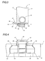
- the retaining head 14 is for example substantially square or rectangular, with rounded corners. In the embodiment shown on the Figures 1 to 10 , it is for example of generally square shape with a truncated outer corner ( figure 4 ).
- the connecting web 15 is a hollow structure which connects the retaining head 14 to the lower edge 5 of the body 1 of the backrest. It may be placed on an edge of the retaining head 14, but is more preferably disposed substantially substantially central thereof so as to define a plurality of receiving spaces 16 around it.
- It has a shape of any contour section adapted to ensure a proper positioning and maintenance of the anchor wire 12 mounted around it.
- it is for example of substantially trapezoidal section, while in the second embodiment shown on the Figures 11 to 23 , she presents a section substantially rectangular.
- the connecting web 15 has no sharp corners, but rather rounded areas so as not to weaken the anchoring wire 12 which is wrapped around it and not to create a concentration zone d efforts at this level when a pulling force is exerted on the anchoring wire 12.
- the anchoring wire 12 is preferably a section of steel wire curved locally at several points so as to form a bridge portion 17 extended on either side by two return hooks 18 used for fixing the wire. anchor 12 on the body 1 folder.
- the bridge portion 17 of the anchoring wire 12 comprises a substantially rectilinear central portion 19, extended by two lateral arms 20 extending on either side of the central portion 19 and each continuing by one of the two or more hanging 18.
- the central portion 19 of the bridge portion 17 projects towards the front of the backrest body 1 and constitutes a rectilinear anchoring portion adapted to the secure attachment of child seats in the vehicle.
- the bridge portion 17 is not necessarily horizontal and may for example be inclined upwards as seen in the profile views of the figures 3 and 14 .
- the lateral arms 20 of the bridge portion 17 may be provided on a part of or their entire length.
- the return hooks 18 correspond to the end portions of the anchoring wire 12. They are bent in the manner of a hook to allow locking by hooking the anchoring wire to the body 1 backrest.
- these return hooks 18 can be bent in different directions. In the first embodiment shown on the Figures 1 to 10 , the return hooks 18 are bent outwards, while in the second embodiment shown on the Figures 11 to 23 they are bent upwards and inwards.
- the seat back body 1 has lower child seat anchoring devices which each comprise a pair of lugs 13 and an anchoring wire 12.
- These two lugs 13 each have a substantially square retaining head 14 of which one of the outer corners is truncated, and a connecting web 15 of substantially trapezoidal cross-section disposed substantially in a substantially central portion of the retaining head 14 so as to define three spaces 16 around it located along its inner sides 21, outside 22 and rear 23.
- the bridge portion 17 of the anchoring wire 12 is disposed between the two lugs 13 of the pair of lugs, with its substantially rectilinear central portion 19 projecting towards the front of the body 1 of the backrest in order to serve as a straight part of the anchorage for secure attachment of a child seat.
- the two lateral arms 20 of the bridge portion 17 of the anchoring wire 12 are pressed against the inner sides 21 of the connecting web 15 of the lugs 13. They are housed between the lower edge 5 of the body 1 and the head of the retaining 14 of the lug 13 in the receiving spaces 16 located along these inner sides 21.
- the two hooking returns 18 of the anchor wire 12 each pass between the lower edge 5 of the body 1 of the file and the retaining head 14 of one of the lugs 13 and are wound in a hook each around the connecting web 15 of one of the lugs 13.
- the return hooks 18 are pressed against the rear side 23 and the outer side 22 preferably inclined of the corresponding connecting web 15 and found wedged between the lower edge 5 of the backrest body 1 and the corresponding retaining head 14 in the receiving spaces 16 which are preferably shaped as wedging grooves for the return snaps 18.
- the anchoring wire 12 is thus firmly fixed to the body 1 of the backrest and the absence of play avoids the subsequent vibrations during driving, which are particularly disadvantageous in the automotive field.
- the lugs 13 fulfill a dual function: They guarantee the immobilization of the anchoring wire 12 either laterally or in the other directions, and they ensure the retention in tearing of the anchoring wire 12 in taking up the forces experienced by the anchoring wire 12 when a pulling force is exerted by the child seat on the anchor wire and transmitting these forces to the body 1 of the seat back.
- the body 1 of the seat back has bottom portion child seat anchoring devices which each comprise a single lug 13 and an anchor wire 12.
- This lug 13 generally larger in size than those of the preceding variant, has a substantially rectangular retaining head 14 and a connecting web 15 of section that is also substantially rectangular and of width equivalent to that of the retaining head 14 for a length lower.
- the connecting web 15 is arranged in substantially central part of the retaining head 14 so that its front walls 24 and rear 25 are flush with those of the retaining head 14 and that its side walls 26 are set back relative to those corresponding to the retaining head 14, thus defining two receiving spaces 16 which extend on either side of the connecting core 15 along its side walls 26.
- the bridge portion 17 of the anchoring wire 12 is engaged around the connecting web 15 of the lug 13, with its substantially rectilinear central portion 19 projecting from the front of the front wall 24 of the web. link 15 and forward of the body 1 of the backrest to serve as a straight anchor for securing a secure child seat.
- the two lateral arms 20 of the bridge portion 17 of the anchor wire 12 are disposed on either side of the connecting web 15 bearing against the side walls 26 of the connecting web 15. They are housed between the lower edge 5 of the body 1 and the retaining head 14 of the lug 13 in the receiving spaces 16 situated along these side walls 26.
- the two hooking returns 18 of the anchoring wire 12 which extend in the extension of the lateral arms 20 are bent upwards and inwards, that is to say towards one another. They are engaged through two orifices 27 of the backrest body 1, preferably located on the rear wall 3 of the body 1, then in two orifices 28 of the horizontal tube 10 which extends inside the backrest body 1 in part. bass of it.
- the orifices 27 of the body 1 of the file are located opposite and in the extension of the orifices 28 of the tube 10, so as to give access to the orifices 28 of the tube and thus to allow the return hooks 18 of the wire anchor 12 are engaged in the orifices 28 of the tube 10 passing through the orifices 27 of the backrest body.
- the return hooks 18 are locked in this engaged position due to the inclination of their end towards each other (inwardly) which opposes the withdrawal of the return hooks 18 out of the orifices 28 of the tube 10.
- the anchoring wire 12 is clamped against the side walls 26 of the connecting web 15 by means of its two lateral arms 20 and is anchored in the tube 10 of the backrest body by means of its return hooks 18. It is thus securely attached to the body 1 backrest and any play that may cause undesirable vibrations thereafter is avoided.
- the lug 13 fulfills only the immobilization function of the anchor wire 12 in all directions.
- the pull-out restraint of the anchoring wire 12 is provided by the tube 10 to which are transmitted, via the return hooks 18, the forces experienced by the anchoring wire 12.
- the tube 10 thus takes over the tensile forces exerted on the anchoring wire 12 by the child seat in case of sudden braking during taxi or in case of accident.
- the tube 10 being very strong and rigid, the resistance of the anchoring wire 12 to traction is very important in this variant.
- the immobilization by the lug 13 of the anchoring wire 12 can be further improved by for example providing for the lateral arms 20 slightly inclined towards each other in the direction of the front of the bridge portion 17, that is to say, approaching each other as they approach the central portion 19, as can be seen on the figure 23 .
- the bridge portion 17 of the anchor wire thus has a self-tightening shape around the connecting web 15 of the pin 13 which opposes all recoil movement of the anchor wire 12.
- the pair of lugs 13 of the first variant can be replaced by a single central lug as in the second variant, around which the snap returns 18 of the anchor wire 12 are wound to ensure its immobilization and its withholding.
- it is chosen for the connecting web 15 of the pin 13 a section of shape adapted to achieve the immobilization of the anchoring wire 12.
- the horizontal tube 10 of the second variant may be replaced by any other appropriate stiffening element, linear or of any shape and nature, placed in or against the body 1 backrest.
- the invention also teaches a method of producing an anchoring device adapted to the secure fixing of a child seat on a body 1 of hollow seat back of blown plastic for a motor vehicle.
- one begins by performing, simultaneously with the blow molding of the body 1 backrest, a pair of lugs 13 blow molded at the bottom of the body 1 backrest.
- lugs 13 correspond to those already described with reference to Figures 1 to 4 .
- the body 1 of the back is as shown on the Figures 5 and 6 .
- the anchoring wire 12 is preformed by bending it locally so that it comprises a bridge portion 17 and two return hooks 18 bent outwards as already described.
- the return hooks 18 are shaped in open hooks, their end not being folded towards the bridge portion 17. They thus include a large engagement opening 29.
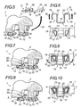
- the preformed anchoring wire 12 is placed in a substantially horizontal lying position and is arranged behind the pins 13 as shown in FIGS. Figures 5 and 6 , the engagement openings 29 of the open hooks formed by its return hooks 18 facing the connection webs 15 of the lugs 13.
- the anchoring wire 12 is then moved forward as symbolized by the arrows 30 of the Figures 5 and 6 and inserting its bridge portion 17 between the two lugs 13, so that its substantially rectilinear central portion 19 projects towards the front of the body 1 of the file, and so that each connecting web 15 of the lugs 13 engages in one of the hooking returns 18 curved in open hooks by its engagement aperture 29.
- the anchoring wire 12 is passed between the backrest body 1 and the retaining head 14 of the lugs 13, the latching returns 18 and the lateral arms 20 of the bridge portion 17 engaging in the receiving spaces 16 located around the connecting web 15.
- a length is preferably chosen for the central portion 19, which corresponds substantially to the spacing between the connecting webs 15 of the lugs 13 so that the lateral arms 20 of the part in bridge 17 are found in abutment against the inner side 21 of the connecting webs 15 when the anchoring wire 12 is inserted between the lugs 13.
- the length of the central portion 19 can even be chosen slightly greater than the spacing between the connecting webs 15 of the lugs 13 so that the bridge portion 17 is mounted somewhat in force between the lugs 13 and that the lateral arms 20 are in a tight abutment against the inner side 21 of the connecting webs 15 thus improving the immobilization of the anchoring wire 12 and ensuring the absence of play at this level.
- the anchoring wire 12 is advanced until the return hooks 18 are pressed against the rear sides 23 of the connecting web 15 of the pins 13. At the end of this engagement step, we find us in the configuration illustrated on the Figures 7 and 8 .
- the last step of this method consists in locking the anchoring wire 12 on the backrest body 1 by means of the snapbacks 18.
- the snapbacks 18 are wrapped around and tightened around the connecting webs 15. on which they are engaged.
- the snap returns 18 are tightened with a tool around the connecting webs 15 during a crimping operation. During this, the free end of the return hooks 18 is pushed against the inclined outer side 22 of the corresponding connecting web 15, as symbolized by the arrows 31 of the figure 8 , so as to close the open hooks formed by the return hooks.
- the free end of the return hooks 18 is preferably pushed further than the outer side 22 of the connecting web 15 so as to deform the plastic material constituting the lug 13. Due to the natural elasticity of the plastic material greater than that of steel, the wall of the bonding web 15 tends to return to its initial position once the crimping operation is complete, while the end free of return hooks 18 remains deformed and pressed into the corresponding wall of the connecting web 15. This provides a reinforced tightening hooking returns 18 around the connecting web 15 lugs 13 without any play, which guarantees a perfect immobilization of the anchoring wire 12 and a lack of vibration at this level thereafter.
- the body 1 of file is in its final configuration shown on the Figures 9 and 10 , the anchoring wire 12 being fixed in position of use on the body 1 of file.
- blow molding of the backrest body 1 starts with a single pin 13 molded by blow molding. in the lower part of the body 1 file.
- This lug 13 corresponds to that described with reference to Figures 11 to 14 .
- the body 1 of file contains in the lower part a stiffening tube 10 which has two orifices 28 as described above.
- This tube 10 can indifferently be inserted into the hollow interior volume of the backrest body 1 after its blow molding or be directly placed in the mold before the blow molding step.
- the body 1 of the back is as shown on the Figures 16 and 17 .
- the anchoring wire 12 is preformed by bending it locally so that it comprises a bridge portion 17 and two return hooks 18 bent in hooks upwards and inwards as already described for the anchor wire 12 shown on the Figures 11 to 15 .
- the preformed anchoring wire 12 is placed in a substantially horizontal lying position. It is disposed in front of the lug 13 at the height of the connecting web 15, the latter facing the opening of the bridge portion 17 of the anchoring wire 12 as shown in FIGS. Figures 16 and 17 .
- the anchoring wire 12 In order to allow mounting of the anchoring wire 12, it is deformed elastically by moving the lateral arms 20 of the bridge portion 17 away from each other, as shown by the arrows 32 of the Figures 16 and 17 . Then, the anchor wire 12 is moved rearward towards the lug 13 according to the arrow 33 of the Figures 18 and 19 in order to engage the central core 15 of the pin 13 in the bridge portion 17 of the anchoring wire 12.
- the anchoring wire 12 is passed between the body 1 of the backrest and the retaining head 14 of the lug 13, and it is moved backwards until the free end of the return hooks 18 opposite holes 27 of the body 1 of the folder as illustrated on the Figures 20 and 21 .
- the spacing of the lateral arms 20 of the bridge portion 17 must be adapted so that the free ends of the two return hooks 18 are found in front of the orifices 27 of the body 1 of the file and can be engaged to the inside of these.
- the anchoring wire 12 whose lateral arms 20 are no longer held apart, is then pulled forward according to the arrows 34 of the Figures 20 and 21 , so as to completely engage the hooking returns 18 of the anchoring wire 12 in the orifices 28 of the tube 10.
- the hooking returns 18 are completely engaged in the orifices 28 of the tube 10 and can not come out again because of their inclination towards the inside, the lateral arms 20 of the bridge portion 17 extend in the receiving spaces 16 and bear against the side walls 26 of the connecting web 15 of the lug 13, and the substantially straight central portion 19 of the bridge portion 17 protrudes forwardly of the body 1 of record.
- the anchoring wire 12 is then in the final position of use as shown on the Figures 22 and 23 .
- the spacing of the lateral arms 20 may advantageously be smaller than the width of the connecting web 15.
- the lateral arms 20 are found in tight support against the side walls 26 of the connecting web 15. The lateral immobilization of the anchor wire is thus greatly improved and any risk of vibration is avoided.
- the preformed anchoring wire 12 may not be placed in front of the lug and mounted rearwardly. It may alternatively be placed under the lug and be mounted upwardly, the lateral arms 20 then have to be spaced apart more significantly in order to cross the retaining head 14 of the lug 13.
Description
La présente invention concerne un dossier de siège pour véhicule, dont le corps est réalisé en matière plastique par soufflage.The present invention relates to a seat back for a vehicle, the body is made of plastic material by blowing.
La présente invention concerne plus précisément un corps de dossier de siège en matière plastique soufflée, équipé de fils d'ancrage destinés à la fixation sécurisée d'un siège enfant dans un véhicule. Il s'agit de préférence de fils d'ancrage normalisés dits « isofix ».The present invention relates more specifically to a plastic seat back body blown, equipped with anchor son for the secure attachment of a child seat in a vehicle. These are preferably standardized anchor wires called "isofix".
L'invention concerne également un procédé de fixation d'un tel fil d'ancrage sur un corps de dossier de siège en matière plastique soufflée.The invention also relates to a method of fixing such an anchor wire on a seat back body made of plastic material blown.
Les dossiers des sièges de véhicule sont généralement formés d'un corps rigide sensiblement plan sur lequel on rajoute un élément de rembourrage, l'ensemble étant ensuite recouvert extérieurement d'un habillage souple par exemple en matière textile, en matière synthétique ou en cuir.The vehicle seat backs are generally formed of a substantially flat rigid body on which is added a padding element, the assembly then being externally covered with a flexible covering for example of textile material, synthetic material or leather.
Dans l'art antérieur, on utilise traditionnellement des corps de dossier de siège en métal qui se présentent sous la forme d'une tôle métallique emboutie comportant une pluralité de nervures de rigidification et sur laquelle des tubes métalliques cintrés sont soudés afin de former un cadre périphérique servant d'armature de rigidification.In the prior art, metal seatback bodies are conventionally used in the form of a stamped metal sheet having a plurality of stiffening ribs and on which bent metal tubes are welded to form a frame. device serving as reinforcing armature.
Les corps de dossier ainsi obtenus présentent une grande rigidité. Cependant, ils sont relativement chers du fait des matériaux utilisés et de leur procédé de fabrication qui requiert de nombreuses étapes. En outre, ils sont également assez lourds ce qui est particulièrement désavantageux dans le domaine automobile.The resulting file bodies have a high rigidity. However, they are relatively expensive because of the materials used and their manufacturing process which requires many steps. In addition, they are also quite heavy which is particularly disadvantageous in the automotive field.
Pour diminuer le poids global des véhicules, une tendance actuelle consiste à tenter de remplacer les corps de dossier métalliques traditionnels par des corps de dossier en matière plastique moulés par soufflage. Un tel corps de dossier de siège en matière plastique soufflée a par exemple été décrit dans la demande de brevet
Les corps de dossier ainsi obtenus sont des pièces creuses beaucoup plus légères, qui présentent de nombreux avantages supplémentaires, comme par exemple leur prix, leur grande facilité de conformation par moulage, et leur volume plus important qui limite la quantité de matière de rembourrage à utiliser.The resulting file bodies are much lighter hollow parts, which have many additional advantages, such as their price, their great ease of conformation by molding, and their larger volume which limits the amount of stuffing material to use .
Cependant, la fixation sur de tels corps de dossier en matière plastique soufflée des éléments techniques annexes devant être rapportés sur le dossier de siège devient problématique du fait des contraintes imposées par le procédé de moulage par soufflage. C'est par exemple le cas des fils d'ancrage, tels que ceux normalisés dits « isofix », destinés à la fixation sécurisée de sièges enfant dans le véhicule.However, the attachment to such plastic blown backs of the technical elements annexes to be reported on the seat back becomes problematic because of the constraints imposed by the blow molding process. This is for example the case of anchor son, such as those standardized so-called "isofix", for the secure attachment of child seats in the vehicle.
Les constructeurs automobile sont de plus en plus nombreux à exiger la présence au niveau des sièges arrière du véhicule d'un ou de plusieurs dispositifs d'ancrage, adaptés pour assurer une fixation appropriée et sécuritaire des sièges enfant de sécurité.More and more car manufacturers are demanding the presence in the rear seats of the vehicle of one or more anchoring devices, adapted to ensure proper and secure attachment of child safety seats.
Il existe une norme internationale appelée « isofix » qui définit les critères à respecter par ces dispositifs d'ancrage pour permettre une installation sécurisée des sièges enfant, compatible avec l'ensemble des modèles de siège enfant respectant la norme et quel que soit le modèle du véhicule.There is an international standard called "isofix" which defines the criteria to be met by these anchoring devices to allow a secure installation of child seats, compatible with all models of child seat respecting the standard and regardless of the model of the child. vehicle.
Selon cette norme, les dispositifs d'ancrage dits « isofix » doivent comporter un fil en acier de 6 mm de diamètre, présentant une partie rectiligne d'ancrage dont la longueur et la position sont imposées. Ces fils d'ancrage « isofix » doivent être très solidement fixés au véhicule de manière à pouvoir résister à une force de 700 daN par fil.According to this standard, the so-called "isofix" anchoring devices must include a
Les sièges enfant, également appelés sièges bébé ou sièges auto, qui respectent cette norme sont pourvus de chaque côté d'une pince susceptible de se clipper sur la partie rectiligne d'ancrage de ces fils d'ancrage « isofix » de manière à réaliser la fixation sécurisée du siège enfant au véhicule.The child seats, also called baby seats or car seats, which comply with this standard are provided on each side with a clip capable of snapping on the rectilinear anchoring part of these anchoring threads "isofix" so as to achieve the secure attachment of the child seat to the vehicle.
Les fils d'ancrage « isofix » devant se trouver à une position normalisée située dans la zone de jonction entre le dossier et l'assise du siège concerné, il est intéressant de les fixer à la partie inférieure du corps de dossier de ce siège.Since the "isofix" anchoring wires must be in a standardized position in the junction area between the backrest and the seat of the seat in question, it is advantageous to fix them to the lower part of the backrest body of this seat.
Selon la pratique antérieure, pour assurer une liaison suffisamment résistante, les extrémités de ces fils d'ancrage étaient classiquement soudées à la tôle métallique formant le corps de dossier de siège ou à un tube en métal lui servant d'armature de rigidification.According to the previous practice, to ensure a sufficiently strong connection, the ends of these anchoring son were conventionally welded to the metal sheet forming the seat back body or a metal tube serving as reinforcing armature.
Cependant, lorsque l'on remplace le corps de dossier métallique par un corps de dossier en matière plastique soufflée, une telle fixation des fils d'ancrage par soudage devient impossible.However, when the metal backrest body is replaced by a blown plastic backrest body, such fixing of the anchoring threads by welding becomes impossible.
L'un des buts de l'invention est de fournir un corps de dossier de siège en matière plastique soufflée, qui comporte au moins un dispositif fixe d'ancrage, notamment « isofix », permettant la fixation sécurisée d'un siège enfant.One of the aims of the invention is to provide a seat back body of blown plastic, which comprises at least one fixed anchoring device, in particular "isofix", allowing the attachment secure child seat.
Pour cela, l'invention enseigne un corps de dossier de siège pour véhicule automobile, creux et en matière plastique soufflée, qui comporte en partie basse au moins un dispositif d'ancrage adapté à la fixation sécurisée d'un siège enfant dans le véhicule.For this, the invention teaches a seat back body for a motor vehicle, hollow and plastic blown, which comprises in the lower part at least one anchoring device adapted to the secure attachment of a child seat in the vehicle.
Ce dispositif d'ancrage comporte :
- au moins un ergot creux en matière plastique soufflée, cet ergot comprenant une tête de retenue reliée au corps de dossier par une âme de liaison plus étroite, lui conférant une forme générale de champignon ; et
- un fil d'ancrage recourbé localement et comportant une partie en pont, qui comprend une portion centrale sensiblement rectiligne prolongée par deux bras latéraux s'étendant de part et d'autre de la portion centrale, et deux retours d'accrochage recourbés en crochets prolongeant chacun l'un des bras latéraux de la partie en pont.
- at least one hollow pin of blown plastic material, this lug comprising a retaining head connected to the backrest body by a narrower connection core, giving it a general mushroom shape; and
- an anchor wire curved locally and having a bridge portion, which comprises a substantially rectilinear central portion extended by two lateral arms extending on either side of the central portion, and two returnees hooked in hooks extending each one of the side arms of the bridge part.
Ce fil d'ancrage passe entre le corps de dossier et la tête de retenue de l'ergot et est fixé au corps de dossier par accrochage au moyen de ses retours d'accrochage, l'ergot contribuant à l'immobilisation du fil d'ancrage.This anchor wire passes between the backrest body and the retaining head of the lug and is fixed to the backrest body by hooking by means of its snapbacks, the lug contributing to the immobilization of the wire. anchorage.
La portion centrale de la partie en pont du fil d'ancrage fait saillie vers l'avant du corps de dossier et constitue une partie rectiligne d'ancrage adaptée à la fixation sécurisée d'un siège enfant dans le véhicule.The central portion of the bridge portion of the anchor wire protrudes forwardly of the backrest body and constitutes a rectilinear anchoring portion adapted to the secure attachment of a child seat in the vehicle.
L'invention fournit également un dossier de siège pour véhicule, notamment automobile, par exemple un dossier de siège individuel ou de banquette, qui comprend un corps de dossier de siège de ce type.The invention also provides a vehicle seat back, particularly an automobile seat, for example an individual seat or bench seat backrest, which comprises a seat back body of this type.
Un autre but de l'invention est de fournir un procédé avantageux, nouveau et original de fixation d'un fil d'ancrage, notamment « isofix », à un corps de dossier de siège en matière plastique soufflée.Another object of the invention is to provide an advantageous, novel and original method of fixing an anchor wire, in particular "isofix", to a seatback body made of blown plastic material.
Ce procédé est compatible avec les contraintes et les règles de conception imposées par le moulage par soufflage du corps de dossier en matière plastique, et assure une fixation suffisamment résistante des fils d'ancrage pour garantir une fixation sécurisée des sièges enfant et respecter la norme « isofix ». Il permet un montage simple et rapide des fils d'ancrage tout en garantissant une fixation solide de ces fils au corps de dossier de siège en matière plastique soufflée.This process is compatible with the constraints and design rules imposed by the blow molding of the plastic backrest body, and ensures a sufficiently strong fixation of the anchoring threads to ensure secure attachment of the child seats and meet the standard " isofix ". It allows a simple and fast mounting of the anchoring son while guaranteeing a solid fixation of these son to the body of plastic seat back blown.
Pour cela, l'invention enseigne un procédé de réalisation d'un dispositif d'ancrage adapté à la fixation sécurisée d'un siège enfant, sur un corps de dossier de siège creux en matière plastique soufflée pour véhicule automobile, en vue de réaliser un corps de dossier de siège selon l'invention.For this, the invention teaches a method of producing an anchoring device adapted to the secure attachment of a child seat, on a hollow seat body of blown plastic for a motor vehicle, in order to achieve a seat back body according to the invention.
Ce procédé prévoit de réaliser, simultanément au moulage par soufflage du corps de dossier, au moins un ergot moulé par soufflage en partie basse du corps de dossier. Cet ergot comprend une tête de retenue reliée au corps de dossier par une âme de liaison plus étroite conférant à cet ergot une forme générale de champignon.This method provides, simultaneously blow molding the backrest body, at least one lug molded by blowing the lower part of the backrest body. This lug comprises a retaining head connected to the backrest body by a narrower connection core conferring on this lug a general shape of mushroom.
On préforme un fil d'ancrage en le recourbant localement de façon qu'il comporte une partie en pont et deux retours d'accrochage recourbés en crochets, la partie en pont comprenant une portion centrale sensiblement rectiligne prolongée par deux bras latéraux qui s'étendent de part et d'autre de la portion centrale, chacun de ces bras latéraux se poursuivant par l'un des retours d'accrochage.An anchoring wire is preformed by bending it locally so that it comprises a bridge portion and two catching hooks curved in hooks, the bridge portion comprising a substantially rectilinear central portion extended by two lateral arms which extend on either side of the central portion, each of these lateral arms continuing with one of the snap returns.
On fait passer ce fil d'ancrage entre le corps de dossier et la tête de retenue de l'ergot, de façon que la portion centrale sensiblement rectiligne de sa partie en pont fasse saillie vers l'avant du corps de dossier.This anchoring wire is passed between the backrest body and the lug retaining head, so that the substantially straight central portion of its bridge portion protrudes forwardly of the backrest body.
On fixe le fil d'ancrage au corps de dossier par accrochage au moyen de ses retours d'accrochage, l'ergot contribuant à l'immobilisation du fil d'ancrage.The anchoring wire is fixed to the backrest body by hooking by means of its return hooks, the lug contributing to the immobilization of the anchoring wire.
Le fil d'ancrage est ainsi solidement fixé sur le corps de dossier et immobilisé dans toutes les directions par l'ergot, la portion centrale sensiblement rectiligne de sa partie en pont constituant alors une partie rectiligne d'ancrage adaptée à la fixation sécurisée de sièges enfant dans le véhicule.The anchoring wire is thus firmly fixed on the backrest body and immobilized in all directions by the lug, the substantially straight central portion of its bridge portion then constituting a rectilinear anchoring portion adapted to the secure attachment of seats. child in the vehicle.
D'autres caractéristiques et avantages de l'invention apparaîtront à la lecture de la description détaillée qui va suivre, description faite en référence aux dessins annexés, dans lesquels :
- la
figure 1 est une vue générale en perspective de l'avant d'un corps de dossier de siège selon une première variante de l'invention ; - la
figure 2 est un agrandissement du détail encerclé sur lafigure 1 , qui illustre plus particulièrement un dispositif d'ancrage fixé en partie basse du corps de dossier selon la première variante de l'invention ; - la
figure 3 est une vue de profil du détail de lafigure 2 ; - la
figure 4 est une vue de dessous du détail de lafigure 2 ; - les
figures 5 à 10 sont des vues schématiques, à chaque fois de face en perspective et de dessous en coupe la tête de retenue des ergots étant enlevée, qui représentent les différentes étapes successives du procédé de réalisation d'un dispositif d'ancrage selon une première variante du procédé selon l'invention et qui correspondent :- pour les
figures 5 et 6 , aux ergots obtenus en partie basse du corps de dossier de siège lors du moulage par soufflage, le fil d'ancrage préformé indépendamment étant positionné en vis-à-vis de ces ergots ; - pour les
figures 7 et 8 , à l'étape d'engagement du fil d'ancrage préformé sur les ergots ; - pour les
figures 9 et 10 , à l'étape de fixation du fil d'ancrage par serrage de ses retours d'accrochage autour des âmes de liaison des ergots ;
- pour les
- la
figure 11 est une vue générale en perspective de l'avant d'un corps de dossier de siège selon une deuxième variante de l'invention ; - la
figure 12 est un agrandissement en perspective du détail encerclé sur lafigure 11 , qui illustre plus particulièrement un dispositif d'ancrage selon la deuxième variante de l'invention ; - la
figure 13 est une vue de profil en perspective du détail de lafigure 12 ; - la
figure 14 est une vue de profil du détail de lafigure 12 ; - la
figure 15 est une vue de profil en perspective du fil d'ancrage et du tube seul, le corps de dossier de siège n'étant pas représenté ; - les
figures 16 à 23 sont des vues schématiques, à chaque fois de dos en perspective et de dessous en coupe la tête de retenue de l'ergot étant enlevée, qui représentent les différentes étapes successives du procédé de réalisation d'un dispositif d'ancrage selon une deuxième variante du procédé selon l'invention et qui correspondent :- pour les
figures 16 et 17 , à l'ergot obtenu en partie basse du corps de dossier de siège lors du moulage par soufflage, le fil d'ancrage préformé indépendamment étant positionné en vis-à-vis de cet ergot ; - pour les
figures 18 et 19 , à l'étape d'écartement des bras latéraux du fil d'ancrage et d'engagement du fil d'ancrage sur l'ergot ; - pour les
figures 20 et 21 , à l'étape d'insertion des extrémités du fil d'ancrage dans les orifices du corps de dossier et les orifices du tube de rigidification ; - pour les
figures 22 et 23 , à l'étape d'engagement des retours d'accrochage du fil d'ancrage dans les orifices du corps de dossier et du tube de rigidification, et d'immobilisation du fil d'ancrage en position finale d'utilisation.
- pour les
- the
figure 1 is a general perspective view of the front of a seat back body according to a first variant of the invention; - the
figure 2 is an enlargement of the detail circled on thefigure 1 , which more particularly illustrates an anchoring device fixed at the bottom of the backrest body according to the first variant of the invention; - the
figure 3 is a profile view of the detail of thefigure 2 ; - the
figure 4 is a bottom view of the detail of thefigure 2 ; - the
Figures 5 to 10 are schematic views, in each case from the front in perspective and from below in section, the retaining head of the lugs being removed, which represent the various successive steps of the method of producing an anchoring device according to a first variant of the method according to the invention and which correspond to:- for the
Figures 5 and 6 , to the lugs obtained at the bottom of the seat back body during blow molding, the independently preformed anchoring wire being positioned opposite these lugs; - for the
Figures 7 and 8 at the step of engaging the preformed anchor wire on the lugs; - for the
Figures 9 and 10 at the step of fixing the anchoring thread by clamping its hooking returns around the connecting webs of the lugs;
- for the
- the
figure 11 is a general perspective view of the front of a seat back body according to a second variant of the invention; - the
figure 12 is a perspective enlargement of the detail circled on thefigure 11 , which more particularly illustrates an anchoring device according to the second variant of the invention; - the
figure 13 is a perspective profile view of the detail of thefigure 12 ; - the
figure 14 is a profile view of the detail of thefigure 12 ; - the
figure 15 is a perspective profile view of the anchor wire and the tube alone, the seat back body not being shown; - the
Figures 16 to 23 are schematic views, each of the back in perspective and below in section the retaining head of the pin being removed, which represent the different successive steps of the method of producing an anchoring device according to a second variant of the process according to the invention and which correspond to:- for the
Figures 16 and 17 , to the lug obtained at the bottom of the seat back body during blow molding, the independently preformed anchor wire being positioned opposite this lug; - for the
Figures 18 and 19 at the step of spacing the lateral arms of the anchor wire and engagement of the anchor wire on the lug; - for the
Figures 20 and 21 at the step of inserting the ends of the anchoring wire into the orifices of the backrest body and the orifices of the stiffening tube; - for the
Figures 22 and 23 at the step of engaging the return hooking of the anchor wire in the holes of the backrest body and the stiffening tube, and immobilizing the anchor wire in the end position of use.
- for the
Le corps de dossier de siège et le procédé selon l'invention vont maintenant être décrits de façon détaillée en référence aux
On définira dans la suite de cette description les notions d'avant et d'arrière en fonction du sens normal de déplacement du véhicule dans lequel le corps de dossier de siège sera monté.In the remainder of this description, the notions of front and rear will be defined according to the normal direction of movement of the vehicle in which the seatback body will be mounted.
Sur les
Ce corps de dossier de siège est destiné à faire partie d'un siège de véhicule, préférentiellement d'un siège automobile. Cependant, l'invention ne se limite pas à cette application préférentielle. Le corps de dossier selon l'invention peut être utilisé pour la réalisation d'un siège prévu pour n'importe quel type de véhicule sur lequel on veut monter un siège enfant de manière sécurisée.This seat back body is intended to be part of a vehicle seat, preferably a car seat. However, the invention is not limited to this preferential application. The backrest body according to the invention can be used for the realization of a seat provided for any type of vehicle on which we want to mount a child seat securely.
De même, ce corps 1 de dossier de siège peut indifféremment faire partie d'un dossier de siège individuel ou de siège multiple tel qu'une banquette par exemple. Les exemples illustrés sur les
Selon l'invention, le corps 1 de dossier de siège est une pièce creuse en matière plastique réalisée par un procédé de moulage par soufflage largement connu de l'homme du métier.According to the invention, the
Le corps 1 représenté comporte deux parois frontales principales : une paroi avant 2 et une paroi arrière 3, ainsi qu'un ensemble de chants comprenant par exemple un chant supérieur 4, un chant inférieur 5 et deux chants latéraux 6. Entre ces différentes parois et chants se trouve un volume intérieur creux fermé.The
Le corps 1 présente une forme globalement plane. Il ne s'agit cependant que d'une forme générale, le corps de dossier de siège pouvant selon les applications présenter sur l'une de ses faces ou sur ses deux faces des formes techniques ou esthétiques quelconques adaptées aux exigences de style de l'application, par exemple convexes, concaves ou avec des nervures ou des renfoncements.The
Selon un mode de réalisation préférentiel, la paroi avant 2 du corps 1 de dossier de siège peut par exemple présenter une forme ergonomique adaptée pour recevoir confortablement le dos d'un ou de plusieurs passagers.According to a preferred embodiment, the
La paroi arrière 3 du corps 1 peut au contraire rester parfaitement plate de manière à pouvoir constituer une prolongation du plancher de coffre dans le cas d'un dossier de siège escamotable.The
Le corps 1 de dossier de siège peut en outre comporter différents renfoncements et logements techniques, par exemple, comme représenté, un enfoncement 7 de la paroi avant 2 servant de logement à l'enrouleur d'une ceinture de sécurité embarquée, un logement de réception 8 pour un accoudoir et/ou des logements cylindriques 9 disposés sur le chant supérieur 4 du corps 1 permettant l'engagement et le maintien de broches de montage d'un ou plusieurs appuie-têtes.The
Afin d'augmenter sa rigidité, le corps 1 de dossier peut comporter dans son volume intérieur un certain nombre de nervures de rigidification internes (non représentées) qui sont formées directement pendant l'étape de moulage par déformation de l'une des parois principales du corps 1 et recollement par thermosoudage de celle-ci sur l'autre de ces parois principales selon une technique connue.In order to increase its rigidity, the
Le corps 1 de dossier peut également être renforcé par un ou plusieurs éléments de rigidification placés dans son volume intérieur creux et par exemple par un ou plusieurs éléments linéaires de rigidification, préférentiellement métalliques, se présentant sous la forme de tubes creux, de profilés pleins à section ronde, carrée ou ovale, ou encore de profilés à section de forme générale en 1 ou en U.The
Sur les modes de réalisation préférentiels représentés sur les
Le tube 10 horizontal, préférentiellement creux et de section circulaire, est disposé dans la partie inférieure du corps 1 de dossier de siège où il s'étend de préférence sur sensiblement toute la largeur du corps 1. Les extrémités de ce tube 10 peuvent être légèrement saillantes à l'extérieur du corps 1 et peuvent avantageusement être utilisées pour réaliser le montage de charnières latérales (non représentées) de fixation du dossier au véhicule.The horizontal tube, preferably hollow and of circular section, is arranged in the lower part of the
Selon l'invention, le corps 1 de dossier de siège comporte en partie basse au moins un dispositif d'ancrage destiné à assurer la fixation sécurisée d'un siège enfant contre le dossier. Ce dispositif d'ancrage comporte un fil d'ancrage 12.According to the invention, the
Lorsque le corps 1 de dossier comporte un tube 10 en partie basse de son volume intérieur, ou un autre élément linéaire de rigidification situé à ce niveau, celui-ci peut être avantageusement utilisé pour participer à la fixation du fil d'ancrage, comme on le verra par la suite dans la partie du descriptif concernant la deuxième variante du procédé selon l'invention.When the
Le corps 1 de dossier de siège selon l'invention comporte également au moins un ergot 13 creux et réalisé en matière plastique soufflée simultanément au reste du corps 1 pendant l'opération de moulage par soufflage.The
Le corps 1 de dossier comprend de préférence deux ergots 13 ou selon les variantes deux paires d'ergots 13, de manière à réaliser deux dispositifs d'ancrage constituant deux points d'ancrage sécurisé en partie basse du corps 1 de dossier. Ces deux ergots 13 ou paires d'ergots 13 sont prévus avec un espacement entre eux correspondant à la distance séparant habituellement les deux pinces de clippage des sièges enfant, cet écartement étant généralement normalisé.The
Bien entendu, le corps de dossier de siège selon l'invention peut comporter un nombre différent d'ergots 13 ou de paires d'ergots 13 et par exemple un nombre supérieur notamment s'il s'agit d'un dossier de siège multiple ou banquette, susceptible de recevoir plusieurs sièges enfant ou d'offrir différents emplacements possible pour un siège enfant, ou un nombre inférieur d'ergots dans le cas d'un modèle de siège enfant ne requérant qu'un unique point d'ancrage pour sa fixation sécurisée.Of course, the seat back body according to the invention may comprise a different number of
Ce ou ces ergots 13 prennent préférentiellement naissance au niveau du chant inférieur 5 du corps 1 et s'étendent vers le bas en sous face du corps 1 de dossier.This or these
Chaque ergot 13 comprend une tête de retenue 14 et une âme de liaison 15 plus étroite, reliant la tête de retenue 14 au corps 1 de dossier et conférant à l'ergot 13 une forme générale de champignon.Each
La tête de retenue 14 est une conformation préférentiellement globalement plane, qui s'étend de préférence sensiblement parallèlement au chant inférieur 5 du corps de dossier et qui définit entre elle et le corps 1 de dossier un ou plusieurs espaces de réception 16 pour le fil d'ancrage 12.The retaining
De préférence, il existe dans l'espace de réception 16 une zone de coincement pour le fil d'ancrage 12 qu'il lui est difficile de quitter.Preferably, there is in the reception space 16 a wedging zone for the
L'épaisseur de la tête de retenue 14 peut être différente selon les endroits. Elle est ainsi préférentiellement plus faible à proximité de l'âme de liaison 15 et augmente progressivement à mesure que l'on s'éloigne de celle-ci de manière à créer une telle zone de coincement dans l'espace de réception 16 à proximité de l'âme de liaison 15. Cependant, cette zone de coincement peut être réalisée d'une façon différente, par exemple par une conformation appropriée du chant inférieur 5 du corps de dossier.The thickness of the retaining
La tête de retenue 14 est par exemple sensiblement carrée ou rectangulaire, à coins arrondis. Sur le mode de réalisation représenté sur les
L'âme de liaison 15 est une structure creuse qui relie la tête de retenue 14 au chant inférieur 5 du corps 1 de dossier. Elle peut être placée sur un bord de la tête de retenue 14, mais est plus préférentiellement disposée en partie sensiblement centrale de celle-ci de manière à définir plusieurs espaces de réception 16 autour d'elle.The connecting
Elle présente une forme de section quelconque de contour adapté pour assurer une mise en place et un maintien satisfaisant du fil d'ancrage 12 monté autour d'elle. Dans le premier mode de réalisation représenté sur les
Dans tous les cas, elle présente un périmètre suffisant pour offrir un ancrage solide et durable au fil d'ancrage 12 monté autour d'elle et accroché à elle, suffisant pour résister aux efforts importants pouvant être exercés sur le siège enfant en cas d'accident.In all cases, it has a perimeter sufficient to provide a strong and
De préférence, l'âme de liaison 15 ne comporte pas d'angles vifs, mais plutôt des zones arrondies afin de ne pas fragiliser le fil d'ancrage 12 qui est enroulé autour d'elle et de ne pas créer de zone de concentration d'efforts à ce niveau lorsqu'une force de traction s'exerce sur le fil d'ancrage 12.Preferably, the connecting
Le fil d'ancrage 12 est de préférence un tronçon de fil d'acier recourbé localement à plusieurs endroits de manière à former une partie en pont 17 prolongée de part et d'autre par deux retours d'accrochage 18 servant à la fixation du fil d'ancrage 12 sur le corps 1 de dossier.The
La partie en pont 17 du fil d'ancrage 12 comprend une portion centrale 19 sensiblement rectiligne, prolongée par deux bras latéraux 20 s'étendant de part et d'autre de la portion centrale 19 et se poursuivant chacun par l'un des retours d'accrochage 18.The
Lorsque le fil d'ancrage 12 est fixé sur le corps 1 de dossier de siège, la portion centrale 19 de la partie en pont 17 fait saillie vers l'avant du corps 1 de dossier et constitue une partie rectiligne d'ancrage adaptée à la fixation sécurisée de sièges enfant dans le véhicule.When the
La partie en pont 17 n'est pas forcément horizontale et peut par exemple être inclinée vers le haut comme on le voit sur les vues de profil des
Les retours d'accrochage 18 correspondent aux portions d'extrémité du fil d'ancrage 12. Ils sont recourbés à la manière d'un crochet afin de permettre le verrouillage par accrochage du fil d'ancrage au corps 1 de dossier.The return hooks 18 correspond to the end portions of the
Selon les variantes, ces retours d'accrochage 18 peuvent être recourbés selon différentes directions. Dans le premier mode de réalisation représenté sur les
Deux variantes différentes du corps 1 de dossier de siège selon l'invention ont été représentées sur les figures annexées et vont être successivement décrites ci-dessous.Two different variants of the
Dans la première variante représentée sur les
Ces deux ergots 13 présentent chacun une tête de retenue 14 sensiblement carrée dont l'un des coins extérieurs est tronqué, et une âme de liaison 15 de section sensiblement trapézoïdale disposée en partie sensiblement centrale de la tête de retenue 14 de manière à définir trois espaces de réception 16 autour d'elle situés le long de ses côtés intérieur 21, extérieur 22 et arrière 23.These two
La partie en pont 17 du fil d'ancrage 12 est disposée entre les deux ergots 13 de la paire d'ergots, avec sa portion centrale 19 sensiblement rectiligne faisant saillie vers l'avant du corps 1 de dossier afin de servir de partie rectiligne d'ancrage pour la fixation sécurisée d'un siège enfant.The
Les deux bras latéraux 20 de la partie en pont 17 du fil d'ancrage 12 sont plaqués contre les côtés intérieurs 21 de l'âme de liaison 15 des ergots 13. Ils sont logés entre le chant inférieur 5 du corps 1 et la tête de retenue 14 de l'ergot 13 dans les espaces de réception 16 situés le long de ces côtés intérieurs 21.The two
Les deux retours d'accrochage 18 du fil d'ancrage 12 passent chacun entre le chant inférieur 5 du corps 1 de dossier et la tête de retenue 14 de l'un des ergots 13 et viennent s'enrouler en crochet chacun autour de l'âme de liaison 15 de l'un des ergots 13.The two hooking
Ces retours d'accrochage 18 sont serrés autour des âmes de liaison 15 des ergots 13 et verrouillent ainsi le fil d'ancrage 12 au corps 1 de dossier.These snap returns 18 are tightened around the connecting
Afin d'éviter tout jeu entre le fil d'ancrage 12 et le corps 1 de dossier, les retours d'accrochage 18 sont plaqués contre le côté arrière 23 et le côté extérieur 22 préférentiellement incliné de l'âme de liaison 15 correspondante et se retrouvent coincés entre le chant inférieur 5 du corps 1 de dossier et la tête de retenue 14 correspondante dans les espaces de réception 16 qui sont de préférence conformés en gorge de coincement pour les retours d'accrochage 18.In order to prevent any play between the
Le fil d'ancrage 12 est ainsi solidement fixé au corps 1 de dossier et l'absence de jeu permet d'éviter les vibrations ultérieures lors du roulage, qui sont particulièrement désavantageuses dans le domaine de l'automobile.The
Dans cette première variante, les ergots 13 remplissent une double fonction : Ils garantissent l'immobilisation du fil d'ancrage 12 que ce soit latéralement ou dans les autres directions, et ils assurent la retenue à l'arrachement du fil d'ancrage 12 en reprenant les efforts subis par le fil d'ancrage 12 lorsqu'une force de traction est exercée par le siège enfant sur le fil d'ancrage et en transmettant ces efforts au corps 1 de dossier de siège.In this first variant, the
Dans la seconde variante représentée sur les
Cet ergot 13, généralement de taille plus importante que ceux de la variante précédent, présente une tête de retenue 14 sensiblement rectangulaire et une âme de liaison 15 de section également sensiblement rectangulaire et de largueur équivalente à celle de la tête de retenue 14 pour une longueur inférieure.This
L'âme de liaison 15 est disposée en partie sensiblement centrale de la tête de retenue 14 de manière que ses parois avant 24 et arrière 25 affleurent avec celles de la tête de retenue 14 et que ses parois latérales 26 se trouvent en retrait par rapport à celles correspondantes de la tête de retenue 14, définissant ainsi deux espaces de réception 16 qui s'étendent de part et d'autre de l'âme de liaison 15 le long de ses parois latérales 26.The connecting
La partie en pont 17 du fil d'ancrage 12 est engagée autour de l'âme de liaison 15 de l'ergot 13, avec sa portion centrale 19 sensiblement rectiligne faisant saillie à l'avant de la paroi avant 24 de l'âme de liaison 15 et vers l'avant du corps 1 de dossier afin de servir de partie rectiligne d'ancrage pour la fixation sécurisée d'un siège enfant.The
Les deux bras latéraux 20 de la partie en pont 17 du fil d'ancrage 12 sont disposés de part et d'autre de l'âme de liaison 15 en appui contre les parois latérales 26 de l'âme de liaison 15. Ils sont logés entre le chant inférieur 5 du corps 1 et la tête de retenue 14 de l'ergot 13 dans les espaces de réception 16 situés le long de ces parois latérales 26.The two
Les deux retours d'accrochage 18 du fil d'ancrage 12 qui s'étendent dans le prolongement des bras latéraux 20 sont recourbés vers le haut et vers l'intérieur, c'est-à-dire l'un vers l'autre. Ils sont engagés à travers deux orifices 27 du corps 1 de dossier, de préférence situés sur la paroi arrière 3 du corps 1, puis dans deux orifices 28 du tube 10 horizontal qui s'étend à l'intérieur du corps 1 de dossier en partie basse de celui-ci.The two hooking
Les orifices 27 du corps 1 de dossier sont situés en vis-à-vis et dans le prolongement des orifices 28 du tube 10, de manière à donner accès aux orifices 28 du tube et ainsi à permettre que les retours d'accrochage 18 du fil d'ancrage 12 soient engagés dans les orifices 28 du tube 10 en passant à travers les orifices 27 du corps de dossier.The
Les retours d'accrochage 18 sont bloqués dans cette position engagée du fait de l'inclinaison de leur extrémité l'une vers l'autre (vers l'intérieur) qui s'oppose au retrait des retours d'accrochage 18 hors des orifices 28 du tube 10.The return hooks 18 are locked in this engaged position due to the inclination of their end towards each other (inwardly) which opposes the withdrawal of the return hooks 18 out of the
Le fil d'ancrage 12 est serré contre les parois latérales 26 de l'âme de liaison 15 au moyen de ses deux bras latéraux 20 et est ancré dans le tube 10 du corps de dossier au moyen de ses retours d'accrochage 18. Il est ainsi solidement fixé au corps 1 de dossier et tout jeu susceptible de causer des vibrations indésirables par la suite est évité.The
Dans cette seconde variante, l'ergot 13 remplit uniquement la fonction d'immobilisation du fil d'ancrage 12 dans toutes les directions. La retenue à l'arrachement du fil d'ancrage 12 est assurée par le tube 10 auquel sont transmis, par l'intermédiaire des retours d'accrochage 18, les efforts subis par le fil d'ancrage 12. Le tube 10 reprend ainsi les efforts de traction exercés sur le fil d'ancrage 12 par le siège enfant en cas de freinage brutal pendant le roulage ou en cas d'accident. Le tube 10 étant très solide et rigide, la résistance du fil d'ancrage 12 à la traction est très importante dans cette variante.In this second variant, the
L'immobilisation par l'ergot 13 du fil d'ancrage 12 peut être encore améliorée en prévoyant par exemple de réaliser les bras latéraux 20 légèrement inclinés l'un vers l'autre en direction de l'avant de la partie en pont 17, c'est-à-dire se rapprochant l'un vers l'autre lorsqu'ils se rapprochent de la portion centrale 19, comme on peut le voir sur la
Bien entendu, les deux variantes qui ont été décrites ci-dessus et représentées sur les différentes figures ne sont que des exemples préférentiels de réalisation, bien d'autres variantes pouvant être imaginées par l'homme du métier sans sortir du cadre de l'invention.Of course, the two variants that have been described above and shown in the various figures are only preferred embodiments, although other variants can be imagined by those skilled in the art without departing from the scope of the invention. .
Par exemple, la paire d'ergots 13 de la première variante peut être remplacée par un ergot central unique comme dans la seconde variante, autour duquel s'enroulent les retours d'accrochage 18 du fil d'ancrage 12 pour assurer son immobilisation et sa retenue à l'arrachement. Dans ce cas, on choisit pour l'âme de liaison 15 de l'ergot 13 une forme de section adaptée pour réaliser l'immobilisation du fil d'ancrage 12.For example, the pair of
De même, on peut également imaginer de remplacer l'ergot 13 central unique de la deuxième variante par une paire d'ergots 13 comme dans la première variante. Dans ce cas, la partie en pont 17 du fil d'ancrage 12 passe entre les deux ergots 13 de la paire d'ergots afin de garantir son blocage latéral et se poursuit comme précédemment par deux retours d'accrochage 18 recourbés vers le haut afin de s'engager dans les deux orifices 28 du tube 10.Similarly, one can also imagine replacing the single
Par ailleurs, le tube horizontal 10 de la deuxième variante peut être remplacé par tout autre élément de rigidification approprié, linéaire ou de forme et de nature quelconques, placé dans ou contre le corps 1 de dossier.Furthermore, the
L'invention enseigne également un procédé de réalisation d'un dispositif d'ancrage adapté à la fixation sécurisée d'un siège enfant, sur un corps 1 de dossier de siège creux en matière plastique soufflée pour véhicule automobile.The invention also teaches a method of producing an anchoring device adapted to the secure fixing of a child seat on a
Deux exemples préférentiels de ce procédé, qui correspondent aux deux variantes de corps de dossier de siège précédemment décrites, ont été représentés schématiquement sur les
Selon le premier exemple du procédé selon l'invention, on commence par réaliser, simultanément au moulage par soufflage du corps 1 de dossier, une paire d'ergots 13 moulés par soufflage en partie basse du corps 1 de dossier. Ces ergots 13 correspondent à ceux déjà décrits en référence aux
A la sortie de l'étape de moulage par soufflage, le corps 1 de dossier se présente comme représenté sur les
Parallèlement à cela, on préforme le fil d'ancrage 12 en le recourbant localement de façon qu'il comporte une partie en pont 17 et deux retours d'accrochage 18 recourbés vers l'extérieur comme déjà décrit. A ce stade, représenté sur les
Le fil d'ancrage 12 préformé est placé en position couchée sensiblement horizontale et est disposé derrière les ergots 13 comme représenté sur les
On déplace ensuite le fil d'ancrage 12 vers l'avant comme symbolisé par les flèches 30 des
Pour cela, on fait passer le fil d'ancrage 12 entre le corps 1 de dossier et la tête de retenue 14 des ergots 13, les retours d'accrochage 18 et les bras latéraux 20 de la partie en pont 17 s'engageant dans les espaces de réception 16 situés autour de l'âme de liaison 15.For this, the
Lorsque l'on préforme le fil d'ancrage 12, on choisit de préférence pour la portion centrale 19 une longueur qui correspond sensiblement à l'écartement entre les âmes de liaison 15 des ergots 13 de façon que les bras latéraux 20 de la partie en pont 17 se retrouvent en appui contre le côté intérieur 21 des âmes de liaison 15 lorsque l'on insère le fil d'ancrage 12 entre les ergots 13. La longueur de la portion centrale 19 peut même être choisie légèrement supérieure à l'écartement entre les âmes de liaison 15 des ergots 13 de façon que la partie en pont 17 soit montée un peu en force entre les ergots 13 et que les bras latéraux 20 se retrouvent en appui serré contre le côté intérieur 21 des âmes de liaison 15 améliorant ainsi l'immobilisation du fil d'ancrage 12 et garantissant l'absence de jeu à ce niveau.When the
Le fil d'ancrage 12 est avancé jusqu'à ce que les retours d'accrochage 18 soient plaqués contre les côtés arrière 23 de l'âme de liaison 15 des ergots 13. A la fin de cette étape d'engagement, on se retrouve dans la configuration illustrée sur les
La dernière étape de ce procédé consiste à verrouiller le fil d'ancrage 12 sur le corps 1 de dossier au moyen des retours d'accrochage 18. Pour cela, on enroule et on serre les retours d'accrochage 18 autour des âmes de liaison 15 sur lesquelles ils sont engagés.The last step of this method consists in locking the
Les retours d'accrochage 18 sont serrés à l'aide d'un outil autour des âmes de liaison 15 au cours d'une opération de sertissage. Pendant celle-ci, l'extrémité libre des retours d'accrochage 18 est repoussée contre le côté extérieur 22 incliné de l'âme de liaison 15 correspondante, comme symbolisé par les flèches 31 de la
Lors de l'opération de sertissage, l'extrémité libre des retours d'accrochage 18 est de préférence repoussée plus loin que le côté extérieur 22 de l'âme de liaison 15 de manière à déformer la matière plastique constitutive de l'ergot 13. Du fait de l'élasticité naturelle de la matière plastique supérieure à celle de l'acier, la paroi de l'âme de liaison 15 a tendance à revenir à sa position initiale une fois l'opération de sertissage terminée, alors que l'extrémité libre des retours d'accrochage 18 reste déformée et enfoncée dans la paroi correspondante de l'âme de liaison 15. On obtient ainsi un serrage renforcé des retours d'accrochage 18 autour de l'âme de liaison 15 des ergots 13 sans aucun jeu, ce qui garantit une immobilisation parfaite du fil d'ancrage 12 et une absence de vibration à ce niveau par la suite.During the crimping operation, the free end of the return hooks 18 is preferably pushed further than the
Après cette opération de serrage, le corps 1 de dossier se trouve dans sa configuration finale représentée sur les
On va maintenant décrire le deuxième exemple de procédé selon l'invention représenté sur les
On commence par réaliser, simultanément au moulage par soufflage du corps 1 de dossier, un ergot 13 unique moulé par soufflage en partie basse du corps 1 de dossier. Cet ergot 13 correspond à celui décrit en référence aux
Le corps 1 de dossier renferme en partie basse un tube 10 de rigidification qui présente deux orifices 28 comme décrit précédemment. Ce tube 10 peut indifféremment être inséré dans le volume intérieur creux du corps 1 de dossier postérieurement à son moulage par soufflage ou être directement placé dans le moule avant l'étape de moulage par soufflage.The
On ménage également dans le corps 1 de dossier deux orifices 27 de préférence situés en face des orifices 28 du tube 10 et donnant accès à ceux-ci.It also provides in the
Avant le montage du fil d'ancrage 12, le corps 1 de dossier se présente comme représenté sur les
Parallèlement à cela, on préforme le fil d'ancrage 12 en le recourbant localement de façon qu'il comporte une partie en pont 17 et deux retours d'accrochage 18 recourbés en crochets vers le haut et vers l'intérieur comme déjà décrit pour le fil d'ancrage 12 représenté sur les
Le fil d'ancrage 12 préformé est placé en position couchée sensiblement horizontale. Il est disposé devant l'ergot 13 à la hauteur de l'âme de liaison 15, celle-ci faisant face à l'ouverture de la partie en pont 17 du fil d'ancrage 12 comme représenté sur les
Afin de permettre le montage du fil d'ancrage 12, on le déforme élastiquement en écartant les bras latéraux 20 de la partie en pont 17 l'un de l'autre, comme symbolisé par les flèches 32 des
Pour cela, on fait passer le fil d'ancrage 12 entre le corps 1 de dossier et la tête de retenue 14 de l'ergot 13, et on le recule jusqu'à placer l'extrémité libre des retours d'accrochage 18 en face des orifices 27 du corps 1 de dossier comme illustré sur les
Bien entendu, l'écartement des bras latéraux 20 de la partie en pont 17 doit être adapté pour que les extrémités libres des deux retours d'accrochage 18 se retrouvent en face des orifices 27 du corps 1 de dossier et puissent être engagées à l'intérieur de ceux-ci.Of course, the spacing of the
On engage alors les extrémités libres des deux retours d'accrochage 18 dans les orifices 27 du corps 1 de dossier, puis dans ceux 28 du tube 10 qui se trouvent dans le prolongement des orifices 27 du corps.We then engage the free ends of the two returns fastening 18 in the
Le fil d'ancrage 12, dont les bras latéraux 20 ne sont plus maintenus en écartement, est alors tiré vers l'avant selon les flèches 34 des
Lors de ce mouvement vers l'avant du fil d'ancrage 12, l'inclinaison vers l'intérieur, c'est-à-dire en direction l'un de l'autre, des deux retours d'accrochage 18 qui s'engagent progressivement dans les orifices 28 du tube 10 provoque automatiquement le rapprochement l'un vers l'autre (reserrage) des bras latéraux 20 de la partie en pont 17 du fil d'ancrage 12 qui pénètrent dans les espaces de réception 16 disposés de part et d'autre de l'âme de liaison 15.During this forward movement of the
Ce résultat est accru par un effet ressort du fil d'ancrage 12 qui a été déformé élastiquement et qui maintenant revient en place de lui-même, ses bras latéraux 20 se rapprochant automatiquement l'un de l'autre par rappel élastique, ce qui provoque un serrage autour l'âme de liaison 15 de l'ergot 13 et un blocage des retours d'accrochage 18 dans le tube 10.This result is increased by a spring effect of the
A la fin du mouvement de translation vers l'avant du fil d'ancrage 12, les retours d'accrochage 18 sont complètement engagés dans les orifices 28 du tube 10 et ne peuvent plus en ressortir du fait de leur inclinaison vers l'intérieur, les bras latéraux 20 de la partie en pont 17 s'étendent dans les espaces de réception 16 et sont en appui contre les parois latérales 26 de l'âme de liaison 15 de l'ergot 13, et la portion centrale 19 sensiblement rectiligne de la partie en pont 17 fait saillie vers l'avant du corps 1 de dossier. Le fil d'ancrage 12 se trouve alors en position finale d'utilisation comme représenté sur les
A l'état libre du fil d'ancrage 12, l'écartement des bras latéraux 20 peut avantageusement être prévu inférieur à la largeur de l'âme de liaison 15. De ce fait, lorsque par la suite le fil d'ancrage 12 est monté sur l'ergot 13, les bras latéraux 20 se retrouvent en appui serré contre les parois latérales 26 de l'âme de liaison 15. L'immobilisation latérale du fil d'ancrage est ainsi grandement améliorée et tout risque de vibration est évité.In the free state of the
Bien entendu, il existe de nombreuses variantes des deux exemples de procédé précédemment décrits. Ainsi par exemple, dans le second procédé, le fil d'ancrage 12 préformé peut ne pas être placé à l'avant de l'ergot et monté par translation vers l'arrière. Il peut alternativement être placé sous l'ergot et être monté par translation vers le haut, les bras latéraux 20 devant alors être écartés de façon plus importante pour pouvoir franchir la tête de retenue 14 de l'ergot 13.Of course, there are many variants of both previously described method examples. Thus, for example, in the second method, the preformed
De manière évidente, l'invention ne se limite pas aux modes de réalisation préférentiels décrits précédemment et représentés sur les différentes figures, l'homme du métier pouvant y apporter de nombreuses modifications et imaginer d'autres variantes sans sortir ni de la portée, ni du cadre de l'invention définis par les revendications.Obviously, the invention is not limited to the preferred embodiments described above and shown in the various figures, the skilled person can make many modifications and imagine other variants without departing from the scope and of the scope of the invention defined by the claims.
Claims (17)
- Seat backrest body (1) for motor vehicle in blow-molded plastic, characterized
in that it comprises, at the bottom, at least one anchoring device suitable for the secure attachment of a child's safety seat within the vehicle ;
in that said anchoring device includes :- at least one hollow blow-molded plastic pin (13), this pin (13) including a retention head (14) connected to the seat backrest body (1) by means of a narrower connecting core (15), endowing it with an approximately mushroom shape ; and- an anchoring wire (12) curved locally and incorporating a bridge part (17) that includes an approximately-rectilinear central part (19) prolonged by two lateral arms (20) extending either side of the central part (19) and two curved, hook-shaped attachment returns (18) each extending from one of the lateral arms (20) of the bridge part (17);in that the anchoring wire (12) passes between the seat backrest body (1) and the pin (13) retention head (14), and is fixed onto the seat backrest body (1) by attachment via its attachment returns (18), with the pin (13) contributing to the immobilization of the anchoring wire (12); and
in that the central part (19) of the bridge part (17) of the anchoring wire (12) is protruding towards the front of the seat backrest body and constitutes a rectilinear anchoring part designed to securely attach a child's safety seat within the vehicle. - Seat backrest body according to claim 1, characterized in that the pin (13) is rooted at the lower edge (5) of the seat backrest body (1) and extends downwards in the bottom face of the seat backrest body (1).
- Seat backrest body (1) according to any one of the preceding claims, characterized in that the retention head (14) is generally flat and defines a reception space (16) for the anchoring wire (12) between it and the seat backrest body (1).
- Seat backrest body (1) according to the preceding claim, characterized in that there is an attachment area for the anchoring wire (12) within the reception space (16).
- Seat backrest body (1) according to any one of the preceding claims, characterized in that the connecting core (15) is of approximately-trapezoidal cross-section, or of approximately-rectangular cross-section.
- Seat backrest body (1) according to any one of the preceding claims, characterized in that the anchoring wire (12) is a length of steel wire.
- Seat backrest body (1) according to any one of the preceding claims, characterized in that the lateral arms (20) of the bridge part (17) are upright, or inclined towards each other in direction of the front of the bridge part (17).
- Seat backrest body (1) according to any one of the preceding claims, characterized in that the attachment returns (18) are curved towards the exterior, or are curved upwards and towards the interior.
- Seat backrest body (1) according to any one of the preceding claims, characterized in that the anchoring device incorporates a pair of pins (13), and in that the bridge part (17) of the anchoring wire (12) is positioned between the two pins (13) of the pair of pins, with the two lateral arms (20) of the bridge part (17) being pressed against the interior sides (21) of the connecting cores (15) of these two pins (13).
- Seat backrest body (1) according to the preceding claim, characterized in that each attachment return (18) of the anchoring wire (12) is rolled and tightened around the connecting core (15) of one of the pins (13) of the pair of pins.
- Seat backrest body (1) according to any one of claims 1 to 8, characterized in that the anchoring device comprises a single pin (13), and in that the bridge part (17) of the anchoring wire (12) is engaged around the connecting core (15) of the pin (13), with the two lateral arms (20) of the bridge part (17) being positioned either side of the connecting core (15), bearing against its lateral walls (26).
- Seat backrest body (1) according to any one of the preceding claims, characterized in that the attachment returns (18) are engaged through two apertures (27) in the seat backrest body (1).
- Seat backrest body (1) according to the preceding claim, characterized in that it comprises at least one tube (10) extending in bottom part of the seat backrest body (1), and in that the attachment returns (18) are engaged through two apertures (28) in this tube (10).
- Method for producing an anchoring device designed for the secure attachment of a child's safety seat onto a hollow seat backrest body (1) in blow-molded plastic for motor vehicles, in order to produce a seat backrest body (1) according to claim 1, the method being characterized in that:- simultaneously during the blow-molding of the seat backrest body (1), at least one pin (13) is produced by blow-molding at the bottom of the seat backrest body (1), with this pin (13) comprising a retention head (14) connected to the seat backrest body (1) by a narrower connecting core (15), endowing it with approximately-mushroom shape;- an anchoring wire (12) is pre-formed by curving it locally so that it comprises a bridge part (17) and two attachment returns (18) curved into hooks, with the bridge part (17) comprising an approximately-rectilinear central part (19) prolonged by two lateral arms (20) extending either side of the central part (19), with each of these lateral arms (20) being prolonged by one of the attachment returns (18);- the anchoring wire (12) is passed between the seat backrest body (1) and the retention head (14) of the pin (13), so that the approximately-rectilinear central part (19) of its bridge part (17) protrudes towards the front of the seat backrest body (1);- the anchoring wire (12) is secured to the seat backrest body (1) by attachment via its attachment returns (18), with the pin (13) contributing to the immobilization of the anchoring wire (12).
- Method for producing an anchoring device according to claim 14, characterized in that:- simultaneously during the blow-molding of the seat backrest body (1), a pair of pins (13) is produced by blow-molding at the bottom of the seat backrest body (1), with these pins (13) comprising a retention head (14) connected to the seat backrest body (1) by a narrower connecting core (15), endowing them with an approximately-mushroom shape;- an anchoring wire (12) is pre-formed by curving it locally so that it comprises a bridge part (17) and two attachment returns (18) curved towards the exterior into open hooks and comprising an engagement opening (29), with the bridge part (17) incorporating an approximately-rectilinear central part (19) prolonged by two lateral arms (20) that extend either side of the central part (19); each of these lateral arms (20) being prolonged by one of the attachment returns (18);- the bridge part (17) of the pre-formed anchoring wire (12) is inserted between the two pins (13) so that the central part (19) protrudes towards the front of the seat backrest body (1), and the connecting core (15) of each of the two pins (13) is engaged into one of the attachment returns (18) curved into open hooks, via its engagement opening (29), with the attachment returns (18) being located between the seat backrest body (1) and the retention head (14) of the pins (13);- the attachment returns (18) are rolled and tightened around the connecting cores (15), on which they are engaged so as to close the open hooks of the attachment returns (18), with the anchoring wire (12) being thus secured onto the seat backrest body (1).
- Method for producing an anchoring device according to claim 15, characterized in that when the attachment returns (18) are tightened around the connecting cores (15), the attachment returns (18) are inserted into the wall of the connecting cores (15), such as to distort the plastic of which the pins (13) are made.
- Method for producing an anchoring device according to claim 14, characterized in that:- simultaneously during the blow-molding of the seat backrest body (1), a single pin (13) is produced by blow-molding at the bottom of the seat backrest body (1), with this pin (13) comprising a retention head (14) connected to the seat backrest body (1) by a narrower connecting core (15), endowing it with an approximately-mushroom shape;- a tube (10) incorporating two apertures (28) is placed within the seat backrest body (1) at the bottom of it, and two apertures (27) are provided in the seat backrest body (1), giving access to the apertures (28) in the tube (10);- an anchoring wire (12) is pre-formed by curving it locally so that it comprises a bridge part (17) and two attachment returns (18) curved into hooks upwards and towards the interior, the bridge part (17) incorporating an approximately-rectilinear central part (19) prolonged by two lateral arms (20) that extend either side of the central part (19); each of these lateral arms (20) being prolonged by one of the attachment returns (18);- the lateral arms (20) of the bridge part (17) are spaced apart, and the central core (15) of the pin (13) is engaged within the bridge part (17) of the anchoring wire (12), the anchoring wire (12) being passed between the seat backrest body (1) and the retention head (14) of the pin (13), until the free end of the attachment returns (18) is positioned facing the apertures (27) of the seat backrest body (1);- the free ends of the attachment returns (18) are engaged into the apertures (27) of the seat backrest body (1), and then into the apertures (28) of the tube (10);- the anchoring wire (12) is pulled forwards, without holding the lateral arms (20) spaced apart, so as to completely engage the attachment returns (18) into the apertures (28) of the tube (10), and so that the central part (19) of the bridge part (17) protrudes towards the front of the seat backrest body (1).
Applications Claiming Priority (1)
| Application Number | Priority Date | Filing Date | Title |
|---|---|---|---|
| FR1001983A FR2959702B1 (en) | 2010-05-07 | 2010-05-07 | FLAT PLASTIC SEAT BACK BODY HAVING AN ANCHORING DEVICE FOR SECURELY ATTACHING A CHILD SEAT. |
Publications (2)
| Publication Number | Publication Date |
|---|---|
| EP2384925A1 EP2384925A1 (en) | 2011-11-09 |
| EP2384925B1 true EP2384925B1 (en) | 2014-05-07 |
Family
ID=43348128
Family Applications (1)
| Application Number | Title | Priority Date | Filing Date |
|---|---|---|---|
| EP20110163766 Not-in-force EP2384925B1 (en) | 2010-05-07 | 2011-04-26 | Seat backrest body made of blow-molded plastic, comprising an anchoring device for secure attachment of a child safety seat |
Country Status (2)
| Country | Link |
|---|---|
| EP (1) | EP2384925B1 (en) |
| FR (1) | FR2959702B1 (en) |
Cited By (1)
| Publication number | Priority date | Publication date | Assignee | Title |
|---|---|---|---|---|
| DE102017106551B4 (en) * | 2016-06-07 | 2020-03-05 | Suzuki Motor Corporation | VEHICLE SEAT BACKREST STRUCTURE |
Families Citing this family (3)
| Publication number | Priority date | Publication date | Assignee | Title |
|---|---|---|---|---|
| DE102014219160A1 (en) * | 2014-09-23 | 2016-03-24 | Volkswagen Aktiengesellschaft | Fastening arrangement in a vehicle |
| JP6872988B2 (en) * | 2017-06-23 | 2021-05-19 | 日本発條株式会社 | A vehicle seat equipped with a child seat mounting device and a child seat mounting device. |
| US20230219473A1 (en) * | 2022-01-07 | 2023-07-13 | Toyota Motor Engineering & Manufacturing North America, Inc. | Seat back frame assemblies and seat assemblies including pultrusion reinforcements |
Family Cites Families (2)
| Publication number | Priority date | Publication date | Assignee | Title |
|---|---|---|---|---|
| US6491346B1 (en) * | 2000-06-01 | 2002-12-10 | Dow Global Technologies, Inc. | Seating system and method for making the same |
| DE102005054299A1 (en) * | 2005-11-11 | 2007-05-16 | Twb Preswerk Gmbh & Co Kg | Fixing device for child seat, has holder e.g. on rear bench seat of motor vehicle whereby holder is displaceably guided by means of guide at rear seatback |
-
2010
- 2010-05-07 FR FR1001983A patent/FR2959702B1/en not_active Expired - Fee Related
-
2011
- 2011-04-26 EP EP20110163766 patent/EP2384925B1/en not_active Not-in-force
Cited By (1)
| Publication number | Priority date | Publication date | Assignee | Title |
|---|---|---|---|---|
| DE102017106551B4 (en) * | 2016-06-07 | 2020-03-05 | Suzuki Motor Corporation | VEHICLE SEAT BACKREST STRUCTURE |
Also Published As
| Publication number | Publication date |
|---|---|
| FR2959702A1 (en) | 2011-11-11 |
| FR2959702B1 (en) | 2012-05-18 |
| EP2384925A1 (en) | 2011-11-09 |
Similar Documents
| Publication | Publication Date | Title |
|---|---|---|
| EP2384925B1 (en) | Seat backrest body made of blow-molded plastic, comprising an anchoring device for secure attachment of a child safety seat | |
| EP2550185A1 (en) | Inflatable airbag arrangement in a dashboard, comprising a flap connected to the dashboard by means of a linear link | |
| FR3052117A1 (en) | VEHICLE SEAT BACKREST PANEL STRUCTURE | |
| WO2005123455A1 (en) | Integrated fixing clip comprising a pivot bolt, which is intended, in particular, for motor vehicle body strips | |
| EP0433100A1 (en) | Device for attaching a seat cover to a motor car seat | |
| EP3568316B1 (en) | Backrest of a rear seat bench of an automotive vehicle comprising a reinforcing panel | |
| FR2952593A1 (en) | Seat backrest e.g. rear bench seat backrest, body rigidifying method for e.g. car, involves inserting linear rigidification element and linear locking element in hollow inner volume, where elements are hollow tube | |
| FR3011207A1 (en) | VEHICLE SEAT ASSEMBLY COMPRISING A RIGID REINFORCEMENT WIRE AND VEHICLE SEAT COMPRISING SUCH A SEAT | |
| EP1043180B1 (en) | Roller blind with handle and indexed hooks, and process for producing the same | |
| EP2127943B1 (en) | Tilting backrest body for a vehicle | |
| EP2729327B1 (en) | Device for attaching an upholstery cover of a motor vehicle seat to the seat framework | |
| FR3068651B1 (en) | ANCHORING DEVICE FOR THE REMOVABLE FIXING OF A CHILD SEAT ON A REAR SEAT OF A FOLDING MOTOR VEHICLE IN A PORTFOLIO. | |
| EP0474558B1 (en) | Fastening device for a tightening band, in particular for a tightening band of a seat cover, method of the assembly of the fastening device on the cloth of the tightening band and tightening band obtained | |
| FR2878206A1 (en) | End clamp groove for e.g. protective bodyside molding, has reinforcing ribs placed perpendicular to longitudinal axis and molded from part with one of lateral walls, where lower side of ribs is not or only punctually connected to lower side | |
| EP4081422B1 (en) | Lightweight suspension layer for a vehicle seat | |
| FR2954242A1 (en) | Backrest for seat of automobile, has two lateral supports, where one of lateral supports situated at lateral edge of housing is hooked on bar without being integrated in manner to transmit torque exerted on support to bar | |
| EP3784522B1 (en) | Pivoting mounting base for the armrest of a seat backrest provided with an anti-tilting metal anchoring element | |
| FR2990659A1 (en) | Shell for backrest of car seat, has map pocket directly fixed at shell frame, and bottom defining back of backrest and upper part of frame, and map pocket defining part whose edges are gripped between bottom and lower part of frame | |
| FR2885278A1 (en) | ARRANGEMENT OF A LOUDSPEAKER GRILLE | |
| EP1907739B1 (en) | Assembly to be mounted under a fixed support such as a motor vehicle body shell floor, and method for using same | |
| FR2926268A1 (en) | Seat element e.g. backrest, for e.g. transport vehicle, has trim cover comprising peripheral edge with folding unit i.e. folding profile, that runs parallel to part of edge of cover, where profile is fixed on part of edge of cover | |
| EP2961631B1 (en) | Motor vehicle seat element, seat equipped with such an element, vehicle equipped with such a seat and method for assembling such an element | |
| EP4185491A1 (en) | Unit with a movable front for attachment of a portable electronic device in a motor vehicle | |
| FR2980417A1 (en) | Trim profile for use in mold of cushion padding of seat of car to ensure accosting of cap covering padding, has bands attached with each other according to longitudinal direction by tubular shaped plastic core that encloses edges of bands | |
| FR2947778A1 (en) | Backrest for seat of motor vehicle, has anchorage comprising bent portion provided with concave part and end portion partially forming loop that is connected to thinner zone of support reinforcement by fixation body |
Legal Events
| Date | Code | Title | Description |
|---|---|---|---|
| AK | Designated contracting states |
Kind code of ref document: A1 Designated state(s): AL AT BE BG CH CY CZ DE DK EE ES FI FR GB GR HR HU IE IS IT LI LT LU LV MC MK MT NL NO PL PT RO RS SE SI SK SM TR |
|
| AX | Request for extension of the european patent |
Extension state: BA ME |
|
| PUAI | Public reference made under article 153(3) epc to a published international application that has entered the european phase |
Free format text: ORIGINAL CODE: 0009012 |
|
| 17P | Request for examination filed |
Effective date: 20111208 |
|
| RIC1 | Information provided on ipc code assigned before grant |
Ipc: B29C 49/48 20060101ALI20131206BHEP Ipc: B60N 2/28 20060101AFI20131206BHEP Ipc: B60N 2/68 20060101ALI20131206BHEP |
|
| GRAP | Despatch of communication of intention to grant a patent |
Free format text: ORIGINAL CODE: EPIDOSNIGR1 |
|
| INTG | Intention to grant announced |
Effective date: 20140129 |
|
| GRAS | Grant fee paid |
Free format text: ORIGINAL CODE: EPIDOSNIGR3 |
|
| GRAA | (expected) grant |
Free format text: ORIGINAL CODE: 0009210 |
|
| AK | Designated contracting states |
Kind code of ref document: B1 Designated state(s): AL AT BE BG CH CY CZ DE DK EE ES FI FR GB GR HR HU IE IS IT LI LT LU LV MC MK MT NL NO PL PT RO RS SE SI SK SM TR |
|
| REG | Reference to a national code |
Ref country code: GB Ref legal event code: FG4D Free format text: NOT ENGLISH |
|
| REG | Reference to a national code |
Ref country code: AT Ref legal event code: REF Ref document number: 666353 Country of ref document: AT Kind code of ref document: T Effective date: 20140515 |
|
| REG | Reference to a national code |
Ref country code: IE Ref legal event code: FG4D Free format text: LANGUAGE OF EP DOCUMENT: FRENCH |
|
| REG | Reference to a national code |
Ref country code: DE Ref legal event code: R096 Ref document number: 602011006693 Country of ref document: DE Effective date: 20140618 |
|
| REG | Reference to a national code |
Ref country code: AT Ref legal event code: MK05 Ref document number: 666353 Country of ref document: AT Kind code of ref document: T Effective date: 20140507 |
|
| REG | Reference to a national code |
Ref country code: NL Ref legal event code: VDEP Effective date: 20140507 |
|
| REG | Reference to a national code |
Ref country code: LT Ref legal event code: MG4D |
|
| PG25 | Lapsed in a contracting state [announced via postgrant information from national office to epo] |
Ref country code: IS Free format text: LAPSE BECAUSE OF FAILURE TO SUBMIT A TRANSLATION OF THE DESCRIPTION OR TO PAY THE FEE WITHIN THE PRESCRIBED TIME-LIMIT Effective date: 20140907 Ref country code: GR Free format text: LAPSE BECAUSE OF FAILURE TO SUBMIT A TRANSLATION OF THE DESCRIPTION OR TO PAY THE FEE WITHIN THE PRESCRIBED TIME-LIMIT Effective date: 20140808 Ref country code: NO Free format text: LAPSE BECAUSE OF FAILURE TO SUBMIT A TRANSLATION OF THE DESCRIPTION OR TO PAY THE FEE WITHIN THE PRESCRIBED TIME-LIMIT Effective date: 20140807 Ref country code: FI Free format text: LAPSE BECAUSE OF FAILURE TO SUBMIT A TRANSLATION OF THE DESCRIPTION OR TO PAY THE FEE WITHIN THE PRESCRIBED TIME-LIMIT Effective date: 20140507 Ref country code: CY Free format text: LAPSE BECAUSE OF FAILURE TO SUBMIT A TRANSLATION OF THE DESCRIPTION OR TO PAY THE FEE WITHIN THE PRESCRIBED TIME-LIMIT Effective date: 20140507 Ref country code: LT Free format text: LAPSE BECAUSE OF FAILURE TO SUBMIT A TRANSLATION OF THE DESCRIPTION OR TO PAY THE FEE WITHIN THE PRESCRIBED TIME-LIMIT Effective date: 20140507 |
|
| PG25 | Lapsed in a contracting state [announced via postgrant information from national office to epo] |
Ref country code: HR Free format text: LAPSE BECAUSE OF FAILURE TO SUBMIT A TRANSLATION OF THE DESCRIPTION OR TO PAY THE FEE WITHIN THE PRESCRIBED TIME-LIMIT Effective date: 20140507 Ref country code: RS Free format text: LAPSE BECAUSE OF FAILURE TO SUBMIT A TRANSLATION OF THE DESCRIPTION OR TO PAY THE FEE WITHIN THE PRESCRIBED TIME-LIMIT Effective date: 20140507 Ref country code: PL Free format text: LAPSE BECAUSE OF FAILURE TO SUBMIT A TRANSLATION OF THE DESCRIPTION OR TO PAY THE FEE WITHIN THE PRESCRIBED TIME-LIMIT Effective date: 20140507 Ref country code: LV Free format text: LAPSE BECAUSE OF FAILURE TO SUBMIT A TRANSLATION OF THE DESCRIPTION OR TO PAY THE FEE WITHIN THE PRESCRIBED TIME-LIMIT Effective date: 20140507 Ref country code: ES Free format text: LAPSE BECAUSE OF FAILURE TO SUBMIT A TRANSLATION OF THE DESCRIPTION OR TO PAY THE FEE WITHIN THE PRESCRIBED TIME-LIMIT Effective date: 20140507 Ref country code: AT Free format text: LAPSE BECAUSE OF FAILURE TO SUBMIT A TRANSLATION OF THE DESCRIPTION OR TO PAY THE FEE WITHIN THE PRESCRIBED TIME-LIMIT Effective date: 20140507 Ref country code: SE Free format text: LAPSE BECAUSE OF FAILURE TO SUBMIT A TRANSLATION OF THE DESCRIPTION OR TO PAY THE FEE WITHIN THE PRESCRIBED TIME-LIMIT Effective date: 20140507 |
|
| PG25 | Lapsed in a contracting state [announced via postgrant information from national office to epo] |
Ref country code: PT Free format text: LAPSE BECAUSE OF FAILURE TO SUBMIT A TRANSLATION OF THE DESCRIPTION OR TO PAY THE FEE WITHIN THE PRESCRIBED TIME-LIMIT Effective date: 20140908 |
|
| PG25 | Lapsed in a contracting state [announced via postgrant information from national office to epo] |
Ref country code: SK Free format text: LAPSE BECAUSE OF FAILURE TO SUBMIT A TRANSLATION OF THE DESCRIPTION OR TO PAY THE FEE WITHIN THE PRESCRIBED TIME-LIMIT Effective date: 20140507 Ref country code: RO Free format text: LAPSE BECAUSE OF FAILURE TO SUBMIT A TRANSLATION OF THE DESCRIPTION OR TO PAY THE FEE WITHIN THE PRESCRIBED TIME-LIMIT Effective date: 20140507 Ref country code: DK Free format text: LAPSE BECAUSE OF FAILURE TO SUBMIT A TRANSLATION OF THE DESCRIPTION OR TO PAY THE FEE WITHIN THE PRESCRIBED TIME-LIMIT Effective date: 20140507 Ref country code: EE Free format text: LAPSE BECAUSE OF FAILURE TO SUBMIT A TRANSLATION OF THE DESCRIPTION OR TO PAY THE FEE WITHIN THE PRESCRIBED TIME-LIMIT Effective date: 20140507 |
|
| REG | Reference to a national code |
Ref country code: DE Ref legal event code: R097 Ref document number: 602011006693 Country of ref document: DE |
|
| PG25 | Lapsed in a contracting state [announced via postgrant information from national office to epo] |
Ref country code: NL Free format text: LAPSE BECAUSE OF FAILURE TO SUBMIT A TRANSLATION OF THE DESCRIPTION OR TO PAY THE FEE WITHIN THE PRESCRIBED TIME-LIMIT Effective date: 20140507 |
|
| PLBE | No opposition filed within time limit |
Free format text: ORIGINAL CODE: 0009261 |
|
| STAA | Information on the status of an ep patent application or granted ep patent |
Free format text: STATUS: NO OPPOSITION FILED WITHIN TIME LIMIT |
|
| 26N | No opposition filed |
Effective date: 20150210 |
|
| PG25 | Lapsed in a contracting state [announced via postgrant information from national office to epo] |
Ref country code: IT Free format text: LAPSE BECAUSE OF FAILURE TO SUBMIT A TRANSLATION OF THE DESCRIPTION OR TO PAY THE FEE WITHIN THE PRESCRIBED TIME-LIMIT Effective date: 20140507 |
|
| REG | Reference to a national code |
Ref country code: DE Ref legal event code: R097 Ref document number: 602011006693 Country of ref document: DE Effective date: 20150210 |
|
| PG25 | Lapsed in a contracting state [announced via postgrant information from national office to epo] |
Ref country code: SI Free format text: LAPSE BECAUSE OF FAILURE TO SUBMIT A TRANSLATION OF THE DESCRIPTION OR TO PAY THE FEE WITHIN THE PRESCRIBED TIME-LIMIT Effective date: 20140507 |
|
| REG | Reference to a national code |
Ref country code: DE Ref legal event code: R119 Ref document number: 602011006693 Country of ref document: DE |
|
| PG25 | Lapsed in a contracting state [announced via postgrant information from national office to epo] |
Ref country code: MC Free format text: LAPSE BECAUSE OF FAILURE TO SUBMIT A TRANSLATION OF THE DESCRIPTION OR TO PAY THE FEE WITHIN THE PRESCRIBED TIME-LIMIT Effective date: 20140507 Ref country code: LU Free format text: LAPSE BECAUSE OF FAILURE TO SUBMIT A TRANSLATION OF THE DESCRIPTION OR TO PAY THE FEE WITHIN THE PRESCRIBED TIME-LIMIT Effective date: 20150426 |
|
| REG | Reference to a national code |
Ref country code: CH Ref legal event code: PL |
|
| GBPC | Gb: european patent ceased through non-payment of renewal fee |
Effective date: 20150426 |
|
| REG | Reference to a national code |
Ref country code: IE Ref legal event code: MM4A |
|
| PG25 | Lapsed in a contracting state [announced via postgrant information from national office to epo] |
Ref country code: DE Free format text: LAPSE BECAUSE OF NON-PAYMENT OF DUE FEES Effective date: 20151103 Ref country code: GB Free format text: LAPSE BECAUSE OF NON-PAYMENT OF DUE FEES Effective date: 20150426 Ref country code: LI Free format text: LAPSE BECAUSE OF NON-PAYMENT OF DUE FEES Effective date: 20150430 Ref country code: CH Free format text: LAPSE BECAUSE OF NON-PAYMENT OF DUE FEES Effective date: 20150430 |
|
| REG | Reference to a national code |
Ref country code: FR Ref legal event code: ST Effective date: 20151231 |
|
| PG25 | Lapsed in a contracting state [announced via postgrant information from national office to epo] |
Ref country code: FR Free format text: LAPSE BECAUSE OF NON-PAYMENT OF DUE FEES Effective date: 20150430 Ref country code: CZ Free format text: LAPSE BECAUSE OF NON-PAYMENT OF DUE FEES Effective date: 20150426 |
|
| PG25 | Lapsed in a contracting state [announced via postgrant information from national office to epo] |
Ref country code: IE Free format text: LAPSE BECAUSE OF NON-PAYMENT OF DUE FEES Effective date: 20150426 |
|
| PG25 | Lapsed in a contracting state [announced via postgrant information from national office to epo] |
Ref country code: MT Free format text: LAPSE BECAUSE OF FAILURE TO SUBMIT A TRANSLATION OF THE DESCRIPTION OR TO PAY THE FEE WITHIN THE PRESCRIBED TIME-LIMIT Effective date: 20140507 |
|
| PG25 | Lapsed in a contracting state [announced via postgrant information from national office to epo] |
Ref country code: SM Free format text: LAPSE BECAUSE OF FAILURE TO SUBMIT A TRANSLATION OF THE DESCRIPTION OR TO PAY THE FEE WITHIN THE PRESCRIBED TIME-LIMIT Effective date: 20140507 Ref country code: BG Free format text: LAPSE BECAUSE OF FAILURE TO SUBMIT A TRANSLATION OF THE DESCRIPTION OR TO PAY THE FEE WITHIN THE PRESCRIBED TIME-LIMIT Effective date: 20140507 Ref country code: HU Free format text: LAPSE BECAUSE OF FAILURE TO SUBMIT A TRANSLATION OF THE DESCRIPTION OR TO PAY THE FEE WITHIN THE PRESCRIBED TIME-LIMIT; INVALID AB INITIO Effective date: 20110426 |
|
| PG25 | Lapsed in a contracting state [announced via postgrant information from national office to epo] |
Ref country code: BE Free format text: LAPSE BECAUSE OF NON-PAYMENT OF DUE FEES Effective date: 20150430 |
|
| PG25 | Lapsed in a contracting state [announced via postgrant information from national office to epo] |
Ref country code: TR Free format text: LAPSE BECAUSE OF FAILURE TO SUBMIT A TRANSLATION OF THE DESCRIPTION OR TO PAY THE FEE WITHIN THE PRESCRIBED TIME-LIMIT Effective date: 20140507 |
|
| PG25 | Lapsed in a contracting state [announced via postgrant information from national office to epo] |
Ref country code: MK Free format text: LAPSE BECAUSE OF FAILURE TO SUBMIT A TRANSLATION OF THE DESCRIPTION OR TO PAY THE FEE WITHIN THE PRESCRIBED TIME-LIMIT Effective date: 20140507 |
|
| PG25 | Lapsed in a contracting state [announced via postgrant information from national office to epo] |
Ref country code: AL Free format text: LAPSE BECAUSE OF FAILURE TO SUBMIT A TRANSLATION OF THE DESCRIPTION OR TO PAY THE FEE WITHIN THE PRESCRIBED TIME-LIMIT Effective date: 20140507 |