EP0473904B1 - Barre pour guider des bords de tête pour joindre par soudure - Google Patents
Barre pour guider des bords de tête pour joindre par soudure Download PDFInfo
- Publication number
- EP0473904B1 EP0473904B1 EP91111466A EP91111466A EP0473904B1 EP 0473904 B1 EP0473904 B1 EP 0473904B1 EP 91111466 A EP91111466 A EP 91111466A EP 91111466 A EP91111466 A EP 91111466A EP 0473904 B1 EP0473904 B1 EP 0473904B1
- Authority
- EP
- European Patent Office
- Prior art keywords
- insert
- groove
- rail according
- enlargement
- pin
- Prior art date
- Legal status (The legal status is an assumption and is not a legal conclusion. Google has not performed a legal analysis and makes no representation as to the accuracy of the status listed.)
- Expired - Lifetime
Links
Images
Classifications
-
- B—PERFORMING OPERATIONS; TRANSPORTING
- B23—MACHINE TOOLS; METAL-WORKING NOT OTHERWISE PROVIDED FOR
- B23K—SOLDERING OR UNSOLDERING; WELDING; CLADDING OR PLATING BY SOLDERING OR WELDING; CUTTING BY APPLYING HEAT LOCALLY, e.g. FLAME CUTTING; WORKING BY LASER BEAM
- B23K37/00—Auxiliary devices or processes, not specially adapted to a procedure covered by only one of the preceding main groups
- B23K37/04—Auxiliary devices or processes, not specially adapted to a procedure covered by only one of the preceding main groups for holding or positioning work
- B23K37/053—Auxiliary devices or processes, not specially adapted to a procedure covered by only one of the preceding main groups for holding or positioning work aligning cylindrical work; Clamping devices therefor
Definitions
- Such a rail in the form of a so-called Z-rail is known from document WO90 / 02016.
- This Z-rail has an upper and a lower support body, into each of which an upper or lower longitudinal groove is machined from one side.
- An insert is fastened in each of the longitudinal grooves in which a guide groove for a sheet metal edge is formed.
- the inserts consist of tungsten carbide or ceramic material such as silicon nitrite, aluminum oxide or other abrasion-resistant, electrically non-conductive material and are fixed in the supporting body by gluing; only then are their guide grooves formed by grinding. If the inserts are worn out, you have to they are exchanged together with the support body, since the inserts cannot be replaced on the spot.
- a Z-rail which has two superimposed support bodies, to which sliding bodies are attached.
- the sliding bodies are profiled in such a step-like manner and arranged in an interlocking manner that they jointly form two superimposed and overlapping longitudinal grooves for guiding one sheet edge each.
- By adjusting the sliding bodies the overlap and height distance of the two sheet metal edges can be changed within certain limits.
- the production of these step-shaped profiled sliding bodies is expensive. If the sliding bodies are made of hard material, for example of tungsten carbide or a ceramic material, then they are sensitive to impact and there is a risk that they break on the associated supporting bodies even if the clamping bodies are not carefully tightened.
- the invention is therefore based on the object of developing a rail for guiding at least one of two sheet metal edges to be welded to one another in such a way that wear occurring on them can be eliminated quickly and at low cost.
- the or each insert only has to support and guide the edge of the associated sheet metal edge. Therefore the insert can be free of any groove or gradation.
- the groove side surfaces which, in contrast to the known rails described, are formed by the support body itself in the rail according to the invention are only slightly loaded by the lateral sheet metal edge surfaces which they have to guide. These lateral sheet metal edge surfaces are also usually rolled surfaces which are smooth compared to the mostly punched or cut edge of the sheet metal edge and accordingly generate little friction.
- the support body can therefore consist, for example, of conventional tool steel without significant wear and tear being expected on the groove side surfaces.
- the support body can be hardened and / or coated, e.g. for insulation reasons with AlO2.
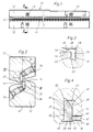
- the Z-rail shown has two supporting bodies 12, which are designed symmetrically to one another with respect to a longitudinal central axis A of the Z-rail and are made in one piece from tool steel.
- Each of the support bodies 12 has a longitudinal groove 14 with two parallel groove side surfaces 16 in the installed position and a vertical groove base surface 18. Inside each support body 12, the associated longitudinal groove 14 has an extension 20 that extends from the groove base surface 18, a counter surface 22 parallel thereto and one normal flank 24 in the installed position. Opposite the extension 20, a bulge 26 is formed in each longitudinal groove 14 and is delimited by a counter flank 28 parallel to the flank 24. The enlargement 20 and bulge 26 of each longitudinal groove 14 thus form a cavity of rectangular cross section, which, however, has rounded recesses 30 instead of corners.
- An insert 32 made of hard, wear-resistant material is fastened in each of the extensions 20, for example made of hard metal or ceramic material.
- the insert has a rectangular cross section and extends into the opposite bulge 26.
- Pins 34 are screwed into each of the supporting bodies 12 at longitudinal intervals, each of which has a foot 36 protruding into the extension 20.
- Each of the pins 34 is inclined at an angle of 45 ° to 75 °, preferably approximately 60 °, against the vertical longitudinal center plane B of the Z-rail 10 and presses with a foot 36 against a correspondingly inclined contact surface 38 on the associated insert 32 the inserts 32 are thus pressed by the associated pins 34 against the associated groove base 18 and counter flank 28 and thereby rigidly fastened in the support body 12.
- Each of the inserts 32 has an outer surface 40 facing away from the associated groove base surface 18 and parallel to it, on which a sheet metal edge 42 of a can frame is supported and guided with its punched or cut edge 44.
- One of the groove side surfaces 16 formed on the supporting body 12 is assigned as the guide surface to the side edge surfaces 46 of the sheet metal edge 42 facing away from one another.
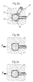
- the inserts 32 can have a different profile shape instead of the rectangular profile shown in FIGS. 2 to 4. Examples of such other profiles are shown in FIGS. 5a to 5c, namely a hexagonal profile in FIG. 5a, an octagonal profile in FIG. 5b and a circular profile in FIG. 5c. All of these inserts 32 can be rotated and reused several times if they are worn on their surfaces previously used as contact surfaces for the edge 44 of a sheet metal edge 42.
- Pins 34 can be used to clamp the inserts 32.
- such pins can be arranged such that they exert forces in the direction of arrows P on the inserts 32 according to FIGS. 5b and 5c, that is to say forces which counteract the contact forces of the sheet metal edges 42.
Claims (8)
- Barre de guidage d'au moins l'un de deux bords de tôle (42), notamment des deux bords longitudinaux de corps cylindriques de boîtes de conserves, devant être soudés entre eux, comprenant :- un corps de support (12), comportant une gorge longitudinale (14) qui présente deux surfaces latérales de gorge (16), au moins approximativement parallèles entre elles, et une surface de fond de gorge (18), au moins approximativement perpendiculaire à ces surfaces latérales, et- une pièce rapportée (32) en matière dure qui est fixée dans la gorge longitudinale (14) et prend appui sur la surface de fond (18) de cette dernière,
caractérisée en ce que- la gorge longitudinale (14) comporte une forme profilée en contre-dépouille présentant une partie plus large (20) par laquelle l'une des surfaces latérales de gorge (16) est séparée de la surface de fond de gorge (18),- la pièce rapportée (32) est fixée dans la partie plus large (20) d'une manière permettant de la remplacer, s'étend de cette partie plus large (20) au moins jusqu'au plan de la surface latérale de gorge (16) opposée et comporte une surface extérieure (40) disposée du côté opposé à la surface de fond de gorge (18) et servant d'appui au chant (44) du bord de tôle (42) et- les surfaces latérales de gorge (16) du corps de support (12) sont agencées de façon à assurer un guidage direct des surfaces latérales (46) du bord de tôle (42). - Barre suivant la revendication 1, caractérisée en ce que la pièce rapportée (32) possède une section transversale de forme polygonale régulière.
- Barre suivant l'une des revendications 1 et 2, caractérisée en ce que la gorge longitudinale (14) a des deux côtés une forme en contre-dépouille, de sorte qu'un évidement (26) est situé en regard de la partie plus large (20), et en ce que la pièce rapportée (32) s'étend, dans le sens transversal à la gorge longitudinale (14), de la partie plus large (20) jusque dans l'évidement (26).
- Barre suivant la revendication 3, caractérisée en ce que la partie plus large (20) et l'évidement (26) constituent ensemble une forme profilée qui est adaptée à la pièce rapportée (32) et qui, à la plaque des coins, comporte des rainures (30) arrondies.
- Barre suivant l'une des revendications 1 à 4, caractérisée en ce qu'au moins un perçage, qui sert à recevoir un goujon (34) permettant l'immobilisation de la pièce rapportée (32), débouche dans la partie plus large (20).
- Barre suivant la revendication 5, caractérisée en ce que le goujon (34) est un goujon fileté.
- Barre suivant l'une des revendications 5 et 6, caractérisée en ce que le goujon (34) fait avec la surface de fond de gorge (18) un angle (β) tel qu'une force exercée par le goujon (34) sur la pièce rapportée (32) comporte une composante qui repousse la pièce rapportée (32) vers la surface latérale de gorge (16) opposée.
- Barre suivant l'une des revendications 5 à 7, caractérisée en ce que la pièce rapportée (32) possède une surface biseautée (38) servant d'appui à un pied (36) du goujon (34).
Applications Claiming Priority (2)
| Application Number | Priority Date | Filing Date | Title |
|---|---|---|---|
| CH2584/90 | 1990-08-07 | ||
| CH2584/90A CH682730A5 (de) | 1990-08-07 | 1990-08-07 | Schiene zum Führen miteinander zu verschweissender Blechränder. |
Publications (3)
| Publication Number | Publication Date |
|---|---|
| EP0473904A2 EP0473904A2 (fr) | 1992-03-11 |
| EP0473904A3 EP0473904A3 (en) | 1992-06-10 |
| EP0473904B1 true EP0473904B1 (fr) | 1994-04-20 |
Family
ID=4237082
Family Applications (1)
| Application Number | Title | Priority Date | Filing Date |
|---|---|---|---|
| EP91111466A Expired - Lifetime EP0473904B1 (fr) | 1990-08-07 | 1991-07-10 | Barre pour guider des bords de tête pour joindre par soudure |
Country Status (9)
| Country | Link |
|---|---|
| US (1) | US5103070A (fr) |
| EP (1) | EP0473904B1 (fr) |
| JP (1) | JPH0688156B2 (fr) |
| BR (1) | BR9103381A (fr) |
| CA (1) | CA2047883C (fr) |
| CH (1) | CH682730A5 (fr) |
| DE (2) | DE4027512C1 (fr) |
| DK (1) | DK0473904T3 (fr) |
| ES (1) | ES2053245T3 (fr) |
Families Citing this family (3)
| Publication number | Priority date | Publication date | Assignee | Title |
|---|---|---|---|---|
| DE4434134A1 (de) * | 1994-09-24 | 1996-03-28 | Kabelmetal Electro Gmbh | Verfahren zur Herstellung eines längsnahtgeschweißten Metallrohres |
| US20180001370A1 (en) | 2014-05-28 | 2018-01-04 | Taylor-Winfield Technologies, Inc. | Barrel tank seam welder system |
| CN107283102A (zh) * | 2017-08-08 | 2017-10-24 | 柳州市开宇机器人有限公司 | 一种上板机焊接器 |
Family Cites Families (6)
| Publication number | Priority date | Publication date | Assignee | Title |
|---|---|---|---|---|
| DE2103551B2 (de) * | 1970-02-10 | 1974-10-17 | Paul Bergdietikon Opprecht (Schweiz) | Elektrische Widerstands-Rollennahtschweißmaschine |
| IT1171949B (it) * | 1983-09-26 | 1987-06-10 | Cefin Spa | Dispositivo per posizionare lembi metallici da unire tra loro con saldatura a sovrapposizione |
| US4635841A (en) * | 1983-12-21 | 1987-01-13 | Cantec, Inc. | Method for bringing together the edges of a blank of sheet metal rolled to a cylinder as well as a guide apparatus for performing the method |
| JPS60180678A (ja) * | 1984-02-27 | 1985-09-14 | Daiwa Can Co Ltd | 溶接缶のブランクガイド用ζバ− |
| CH674169A5 (fr) * | 1987-05-11 | 1990-05-15 | Elpatronic Ag | |
| WO1990002016A1 (fr) * | 1988-08-26 | 1990-03-08 | Elpatronic Ag | Barre profilee en z servant au formage de materiau pour boites, pour boissons |
-
1990
- 1990-08-07 CH CH2584/90A patent/CH682730A5/de not_active IP Right Cessation
- 1990-08-30 DE DE4027512A patent/DE4027512C1/de not_active Expired - Fee Related
-
1991
- 1991-07-05 US US07/726,294 patent/US5103070A/en not_active Expired - Lifetime
- 1991-07-10 DK DK91111466.8T patent/DK0473904T3/da active
- 1991-07-10 DE DE59101433T patent/DE59101433D1/de not_active Expired - Fee Related
- 1991-07-10 ES ES91111466T patent/ES2053245T3/es not_active Expired - Lifetime
- 1991-07-10 EP EP91111466A patent/EP0473904B1/fr not_active Expired - Lifetime
- 1991-07-25 CA CA002047883A patent/CA2047883C/fr not_active Expired - Fee Related
- 1991-08-02 JP JP3193827A patent/JPH0688156B2/ja not_active Expired - Fee Related
- 1991-08-06 BR BR919103381A patent/BR9103381A/pt not_active IP Right Cessation
Also Published As
| Publication number | Publication date |
|---|---|
| JPH04231198A (ja) | 1992-08-20 |
| EP0473904A2 (fr) | 1992-03-11 |
| CH682730A5 (de) | 1993-11-15 |
| DK0473904T3 (da) | 1994-08-08 |
| JPH0688156B2 (ja) | 1994-11-09 |
| DE4027512C1 (fr) | 1992-04-23 |
| DE59101433D1 (de) | 1994-05-26 |
| US5103070A (en) | 1992-04-07 |
| EP0473904A3 (en) | 1992-06-10 |
| CA2047883C (fr) | 1995-04-25 |
| ES2053245T3 (es) | 1994-07-16 |
| CA2047883A1 (fr) | 1992-02-08 |
| BR9103381A (pt) | 1992-05-12 |
Similar Documents
| Publication | Publication Date | Title |
|---|---|---|
| EP0052196A1 (fr) | Boîte de couleurs pour une machine à imprimer | |
| DE202005016610U1 (de) | Wendeschneidplatte für einen Drehmeißel | |
| EP2368817B1 (fr) | Dispositif de guidage | |
| DE3304783C2 (fr) | ||
| EP1670608A1 (fr) | Insert de coupe | |
| EP0286647B1 (fr) | Dispositif de serrage de plaques ignifuges dans le cadre metallique d'enclenchements a arbres | |
| DE2421328C2 (de) | Linear-Rollenlager | |
| EP2136963B1 (fr) | Tablier à maillons | |
| EP0473904B1 (fr) | Barre pour guider des bords de tête pour joindre par soudure | |
| AT397221B (de) | Gradführung für transportschlitten | |
| EP0549816A1 (fr) | Elément de grille pour la construction d'un grille | |
| DD232447A5 (de) | Verschlussplatte fuer einen schiebeverschluss | |
| DE3420653A1 (de) | Schneid- oder abstechwerkzeug | |
| AT1181U1 (de) | Führung für einen schiebetisch | |
| DE3637985C2 (de) | Biegestanze | |
| DE2753284C2 (de) | Schmitzringanordnung zwischen zwei Druckwerkszylindern | |
| EP1882554B1 (fr) | Dispositif destiné à régler des crayons de positionnement destinés à la fixation en place de pièces à usiner sur des portes-pièces | |
| EP1657361B1 (fr) | Coeur pour aiguillages | |
| DE469755C (de) | Aus aufeinandergelegten Federblaettern bestehende Tragfeder | |
| DE2210038A1 (de) | Fundamentbefestigung für Werkzeugmaschinenbetten | |
| EP0254034A2 (fr) | Encrier comportant un dispositif de dosage de l'encre pour machines d'impression offset ou typographique | |
| DE3828482C2 (de) | Stoss- oder Ziehwerkzeug | |
| CH716075A1 (de) | Fixkammhalter für eine Kämmmaschine. | |
| AT524404B1 (de) | Werkzeugeinsatz für Abkantpressen | |
| DE19722839C1 (de) | Schneidbacke für Gewindeschere |
Legal Events
| Date | Code | Title | Description |
|---|---|---|---|
| PUAI | Public reference made under article 153(3) epc to a published international application that has entered the european phase |
Free format text: ORIGINAL CODE: 0009012 |
|
| AK | Designated contracting states |
Kind code of ref document: A2 Designated state(s): CH DE DK ES FR GB IT LI SE |
|
| PUAL | Search report despatched |
Free format text: ORIGINAL CODE: 0009013 |
|
| AK | Designated contracting states |
Kind code of ref document: A3 Designated state(s): CH DE DK ES FR GB IT LI SE |
|
| 17P | Request for examination filed |
Effective date: 19920508 |
|
| 17Q | First examination report despatched |
Effective date: 19930920 |
|
| GRAA | (expected) grant |
Free format text: ORIGINAL CODE: 0009210 |
|
| AK | Designated contracting states |
Kind code of ref document: B1 Designated state(s): CH DE DK ES FR GB IT LI SE |
|
| ITF | It: translation for a ep patent filed |
Owner name: DE DOMINICIS & MAYER S.R.L. |
|
| REF | Corresponds to: |
Ref document number: 59101433 Country of ref document: DE Date of ref document: 19940526 |
|
| ET | Fr: translation filed | ||
| GBT | Gb: translation of ep patent filed (gb section 77(6)(a)/1977) |
Effective date: 19940609 |
|
| REG | Reference to a national code |
Ref country code: ES Ref legal event code: FG2A Ref document number: 2053245 Country of ref document: ES Kind code of ref document: T3 |
|
| REG | Reference to a national code |
Ref country code: DK Ref legal event code: T3 |
|
| EAL | Se: european patent in force in sweden |
Ref document number: 91111466.8 |
|
| PLBE | No opposition filed within time limit |
Free format text: ORIGINAL CODE: 0009261 |
|
| STAA | Information on the status of an ep patent application or granted ep patent |
Free format text: STATUS: NO OPPOSITION FILED WITHIN TIME LIMIT |
|
| 26N | No opposition filed | ||
| REG | Reference to a national code |
Ref country code: CH Ref legal event code: PFA Free format text: ELPATRONIC AG,BAARERSTRASSE 112,6300 ZUG (CH) TRANSFER- ELPATRONIC AG,INDUSTRIESTRASSE 35,8962 BERGDIETIKON (CH) |
|
| REG | Reference to a national code |
Ref country code: GB Ref legal event code: IF02 |
|
| PGFP | Annual fee paid to national office [announced via postgrant information from national office to epo] |
Ref country code: FR Payment date: 20030619 Year of fee payment: 13 |
|
| PGFP | Annual fee paid to national office [announced via postgrant information from national office to epo] |
Ref country code: ES Payment date: 20030627 Year of fee payment: 13 |
|
| PGFP | Annual fee paid to national office [announced via postgrant information from national office to epo] |
Ref country code: GB Payment date: 20030630 Year of fee payment: 13 |
|
| PGFP | Annual fee paid to national office [announced via postgrant information from national office to epo] |
Ref country code: CH Payment date: 20030707 Year of fee payment: 13 |
|
| PGFP | Annual fee paid to national office [announced via postgrant information from national office to epo] |
Ref country code: DE Payment date: 20030722 Year of fee payment: 13 |
|
| PGFP | Annual fee paid to national office [announced via postgrant information from national office to epo] |
Ref country code: DK Payment date: 20030724 Year of fee payment: 13 |
|
| PGFP | Annual fee paid to national office [announced via postgrant information from national office to epo] |
Ref country code: SE Payment date: 20030730 Year of fee payment: 13 |
|
| PG25 | Lapsed in a contracting state [announced via postgrant information from national office to epo] |
Ref country code: GB Free format text: LAPSE BECAUSE OF NON-PAYMENT OF DUE FEES Effective date: 20040710 |
|
| PG25 | Lapsed in a contracting state [announced via postgrant information from national office to epo] |
Ref country code: SE Free format text: LAPSE BECAUSE OF NON-PAYMENT OF DUE FEES Effective date: 20040711 |
|
| PG25 | Lapsed in a contracting state [announced via postgrant information from national office to epo] |
Ref country code: ES Free format text: LAPSE BECAUSE OF NON-PAYMENT OF DUE FEES Effective date: 20040712 |
|
| PG25 | Lapsed in a contracting state [announced via postgrant information from national office to epo] |
Ref country code: LI Free format text: LAPSE BECAUSE OF NON-PAYMENT OF DUE FEES Effective date: 20040731 Ref country code: CH Free format text: LAPSE BECAUSE OF NON-PAYMENT OF DUE FEES Effective date: 20040731 |
|
| PG25 | Lapsed in a contracting state [announced via postgrant information from national office to epo] |
Ref country code: DK Free format text: LAPSE BECAUSE OF NON-PAYMENT OF DUE FEES Effective date: 20040802 |
|
| PG25 | Lapsed in a contracting state [announced via postgrant information from national office to epo] |
Ref country code: DE Free format text: LAPSE BECAUSE OF NON-PAYMENT OF DUE FEES Effective date: 20050201 |
|
| REG | Reference to a national code |
Ref country code: DK Ref legal event code: EBP |
|
| EUG | Se: european patent has lapsed | ||
| GBPC | Gb: european patent ceased through non-payment of renewal fee |
Effective date: 20040710 |
|
| REG | Reference to a national code |
Ref country code: CH Ref legal event code: PL |
|
| PG25 | Lapsed in a contracting state [announced via postgrant information from national office to epo] |
Ref country code: FR Free format text: LAPSE BECAUSE OF NON-PAYMENT OF DUE FEES Effective date: 20050331 |
|
| REG | Reference to a national code |
Ref country code: FR Ref legal event code: ST |
|
| PG25 | Lapsed in a contracting state [announced via postgrant information from national office to epo] |
Ref country code: IT Free format text: LAPSE BECAUSE OF NON-PAYMENT OF DUE FEES Effective date: 20050710 |
|
| REG | Reference to a national code |
Ref country code: ES Ref legal event code: FD2A Effective date: 20040712 |