EP0473904B1 - Bar for guiding of plate edges for welding - Google Patents
Bar for guiding of plate edges for welding Download PDFInfo
- Publication number
- EP0473904B1 EP0473904B1 EP91111466A EP91111466A EP0473904B1 EP 0473904 B1 EP0473904 B1 EP 0473904B1 EP 91111466 A EP91111466 A EP 91111466A EP 91111466 A EP91111466 A EP 91111466A EP 0473904 B1 EP0473904 B1 EP 0473904B1
- Authority
- EP
- European Patent Office
- Prior art keywords
- insert
- groove
- rail according
- enlargement
- pin
- Prior art date
- Legal status (The legal status is an assumption and is not a legal conclusion. Google has not performed a legal analysis and makes no representation as to the accuracy of the status listed.)
- Expired - Lifetime
Links
Images
Classifications
-
- B—PERFORMING OPERATIONS; TRANSPORTING
- B23—MACHINE TOOLS; METAL-WORKING NOT OTHERWISE PROVIDED FOR
- B23K—SOLDERING OR UNSOLDERING; WELDING; CLADDING OR PLATING BY SOLDERING OR WELDING; CUTTING BY APPLYING HEAT LOCALLY, e.g. FLAME CUTTING; WORKING BY LASER BEAM
- B23K37/00—Auxiliary devices or processes, not specially adapted to a procedure covered by only one of the preceding main groups
- B23K37/04—Auxiliary devices or processes, not specially adapted to a procedure covered by only one of the preceding main groups for holding or positioning work
- B23K37/053—Auxiliary devices or processes, not specially adapted to a procedure covered by only one of the preceding main groups for holding or positioning work aligning cylindrical work; Clamping devices therefor
Definitions
- Such a rail in the form of a so-called Z-rail is known from document WO90 / 02016.
- This Z-rail has an upper and a lower support body, into each of which an upper or lower longitudinal groove is machined from one side.
- An insert is fastened in each of the longitudinal grooves in which a guide groove for a sheet metal edge is formed.
- the inserts consist of tungsten carbide or ceramic material such as silicon nitrite, aluminum oxide or other abrasion-resistant, electrically non-conductive material and are fixed in the supporting body by gluing; only then are their guide grooves formed by grinding. If the inserts are worn out, you have to they are exchanged together with the support body, since the inserts cannot be replaced on the spot.
- a Z-rail which has two superimposed support bodies, to which sliding bodies are attached.
- the sliding bodies are profiled in such a step-like manner and arranged in an interlocking manner that they jointly form two superimposed and overlapping longitudinal grooves for guiding one sheet edge each.
- By adjusting the sliding bodies the overlap and height distance of the two sheet metal edges can be changed within certain limits.
- the production of these step-shaped profiled sliding bodies is expensive. If the sliding bodies are made of hard material, for example of tungsten carbide or a ceramic material, then they are sensitive to impact and there is a risk that they break on the associated supporting bodies even if the clamping bodies are not carefully tightened.
- the invention is therefore based on the object of developing a rail for guiding at least one of two sheet metal edges to be welded to one another in such a way that wear occurring on them can be eliminated quickly and at low cost.
- the or each insert only has to support and guide the edge of the associated sheet metal edge. Therefore the insert can be free of any groove or gradation.
- the groove side surfaces which, in contrast to the known rails described, are formed by the support body itself in the rail according to the invention are only slightly loaded by the lateral sheet metal edge surfaces which they have to guide. These lateral sheet metal edge surfaces are also usually rolled surfaces which are smooth compared to the mostly punched or cut edge of the sheet metal edge and accordingly generate little friction.
- the support body can therefore consist, for example, of conventional tool steel without significant wear and tear being expected on the groove side surfaces.
- the support body can be hardened and / or coated, e.g. for insulation reasons with AlO2.
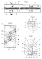
- the Z-rail shown has two supporting bodies 12, which are designed symmetrically to one another with respect to a longitudinal central axis A of the Z-rail and are made in one piece from tool steel.
- Each of the support bodies 12 has a longitudinal groove 14 with two parallel groove side surfaces 16 in the installed position and a vertical groove base surface 18. Inside each support body 12, the associated longitudinal groove 14 has an extension 20 that extends from the groove base surface 18, a counter surface 22 parallel thereto and one normal flank 24 in the installed position. Opposite the extension 20, a bulge 26 is formed in each longitudinal groove 14 and is delimited by a counter flank 28 parallel to the flank 24. The enlargement 20 and bulge 26 of each longitudinal groove 14 thus form a cavity of rectangular cross section, which, however, has rounded recesses 30 instead of corners.
- An insert 32 made of hard, wear-resistant material is fastened in each of the extensions 20, for example made of hard metal or ceramic material.
- the insert has a rectangular cross section and extends into the opposite bulge 26.
- Pins 34 are screwed into each of the supporting bodies 12 at longitudinal intervals, each of which has a foot 36 protruding into the extension 20.
- Each of the pins 34 is inclined at an angle of 45 ° to 75 °, preferably approximately 60 °, against the vertical longitudinal center plane B of the Z-rail 10 and presses with a foot 36 against a correspondingly inclined contact surface 38 on the associated insert 32 the inserts 32 are thus pressed by the associated pins 34 against the associated groove base 18 and counter flank 28 and thereby rigidly fastened in the support body 12.
- Each of the inserts 32 has an outer surface 40 facing away from the associated groove base surface 18 and parallel to it, on which a sheet metal edge 42 of a can frame is supported and guided with its punched or cut edge 44.
- One of the groove side surfaces 16 formed on the supporting body 12 is assigned as the guide surface to the side edge surfaces 46 of the sheet metal edge 42 facing away from one another.
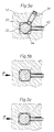
- the inserts 32 can have a different profile shape instead of the rectangular profile shown in FIGS. 2 to 4. Examples of such other profiles are shown in FIGS. 5a to 5c, namely a hexagonal profile in FIG. 5a, an octagonal profile in FIG. 5b and a circular profile in FIG. 5c. All of these inserts 32 can be rotated and reused several times if they are worn on their surfaces previously used as contact surfaces for the edge 44 of a sheet metal edge 42.
- Pins 34 can be used to clamp the inserts 32.
- such pins can be arranged such that they exert forces in the direction of arrows P on the inserts 32 according to FIGS. 5b and 5c, that is to say forces which counteract the contact forces of the sheet metal edges 42.
Description
Die Erfindung betrifft eine Schiene zum Führen mindestens eines von zwei miteinander zu verschweißenden Blechrändern, insbes. Längsrändern von Dosenzargen, mit
- einem Tragkörper mit einer Längsnut, die zwei zueinander mindestens annähernd parallele Nutseitenflächen und eine zu diesen mindestens annähernd lotrechte Nutgrundfläche aufweist, und
- einem Einsatz aus hartem Material, der in der Längsnut befestigt ist und an deren Nutgrundfläche anliegt.
- a supporting body with a longitudinal groove which has two groove side surfaces which are at least approximately parallel to one another and a groove base surface which is at least approximately perpendicular to these, and
- an insert made of hard material, which is fastened in the longitudinal groove and lies against the groove base.
Eine solche Schiene in Gestalt einer sogenannten Z-Schiene ist aus dem Dokument WO90/02016 bekannt. Diese Z-Schiene hat einen oberen und einen unteren Tragkörper, in die von je einer Seite her eine obere bzw. untere Längsnut eingearbeitet ist. In jeder der Längsnuten ist ein Einsatz befestigt, in dem eine Führungsnut für einen Blechrand ausgebildet ist. Die Einsätze bestehen aus Wolframcarbid oder keramischem Werkstoff wie Silikonnitrit, Aluminiumoxid oder anderem abriebfesten, elektrisch nicht leitendem Material und werden durch Kleben im Tragkörper befestigt; erst danach werden ihre Führungsnuten durch Schleifen ausgebildet. Wenn die Einsätze verschlissen sind, müssen sie zusammen mit dem Tragkörper ausgewechselt werden, da eine Erneuerung der Einsätze an Ort und Stelle nicht möglich ist.Such a rail in the form of a so-called Z-rail is known from document WO90 / 02016. This Z-rail has an upper and a lower support body, into each of which an upper or lower longitudinal groove is machined from one side. An insert is fastened in each of the longitudinal grooves in which a guide groove for a sheet metal edge is formed. The inserts consist of tungsten carbide or ceramic material such as silicon nitrite, aluminum oxide or other abrasion-resistant, electrically non-conductive material and are fixed in the supporting body by gluing; only then are their guide grooves formed by grinding. If the inserts are worn out, you have to they are exchanged together with the support body, since the inserts cannot be replaced on the spot.
Aus der DE 3432505 A1 ist eine Z-Schiene bekannt, die zwei übereinander angeordnete Tragkörper aufweist, an denen Gleitkörper befestigt sind. Die Gleitkörper sind derart stufenförmig profiliert und ineinandergreifend angeordnet, daß sie gemeinsam zwei übereinanderliegende und einander überlappende Längsnuten zum Führen je eines Blechrandes bilden. Durch Einstellen der Gleitkörper lassen sich Überlappung und Höhenabstand der beiden Blechränder in bestimmten Grenzen verändern. Die Herstellung dieser stufenförmig profilierten Gleitkörper ist teuer. Wenn die Gleitkörper aus hartem Werkstoff bestehen, beispielsweise aus Wolframcarbid oder einem keramischen Werkstoff, dann sind sie stoßempfindlich, und es besteht die Gefahr, daß sie schon bei unvorsichtigem Festspannen an den zugehörigen Tragkörpern brechen.From DE 3432505 A1 a Z-rail is known which has two superimposed support bodies, to which sliding bodies are attached. The sliding bodies are profiled in such a step-like manner and arranged in an interlocking manner that they jointly form two superimposed and overlapping longitudinal grooves for guiding one sheet edge each. By adjusting the sliding bodies, the overlap and height distance of the two sheet metal edges can be changed within certain limits. The production of these step-shaped profiled sliding bodies is expensive. If the sliding bodies are made of hard material, for example of tungsten carbide or a ceramic material, then they are sensitive to impact and there is a risk that they break on the associated supporting bodies even if the clamping bodies are not carefully tightened.
Der Erfindung liegt deshalb die Aufgabe zugrunde, eine Schiene zum Führen mindestens eines von zwei miteinander zu verschweißenden Blechrändern derart weiterzubilden, daß an ihnen aufgetretener Verschleiß schnell und mit geringen Kosten beseitigt werden kann.The invention is therefore based on the object of developing a rail for guiding at least one of two sheet metal edges to be welded to one another in such a way that wear occurring on them can be eliminated quickly and at low cost.
Die Aufgabe ist erfindungsgemäß ausgehend von einer Schiene der eingangs beschriebenen Gattung dadurch gelöst, daß
- die Längsnut ein hinterschnittenes Profil mit einer Erweiterung aufweist, durch die eine der Nutseitenflächen von der Nutgrundfläche getrennt ist,
- der Einsatz auswechselbar in der Erweiterung befestigt ist, sich von dort aus mindestens bis zur Ebene der gegenüberliegenden Nutseitenfläche erstreckt und eine von der Nutgrundfläche abgewandte Außenfläche zum Abstützen einer Kante des Blechrandes aufweist, und
- die Nutseitenflächen des Tragkörpers zum unmittelbaren Führen von seitlichen Randflächen des Blechrandes ausgebildet sind.
- the longitudinal groove has an undercut profile with an extension through which one of the groove side surfaces is separated from the groove base surface,
- the insert is interchangeably fastened in the extension, extends from there at least to the level of the opposite groove side surface and one of the Groove base surface facing away from supporting an edge of the sheet metal edge, and
- the groove side surfaces of the support body are designed for direct guidance of lateral edge surfaces of the sheet metal edge.
Bei der erfindungsgemäßen Schiene hat der oder jeder Einsatz nur die Kante des zugehörigen Blechrandes abzustützen und zu führen. Deshalb kann der Einsatz frei von jeglicher Nut oder Abstufung sein. Ein derart einfacher Einsatz ist verhältnismäßig leicht herstellbar und wenig bruchempfindlich. Die Nutseitenflächen, die bei der erfindungsgemäßen Schiene im Gegensatz zu den beschriebenen bekannten Schienen vom Tragkörper selbst gebildet sind, werden von den seitlichen Blechrandflächen, die sie zu führen haben, nur wenig belastet. Diese seitlichen Blechrandflächen sind außerdem üblicherweise gewalzte Flächen, die im Vergleich zu der meist gestanzten oder geschnittenen Kante des Blechrandes glatt sind und dementsprechend wenig Reibung erzeugen. Der Tragkörper kann deshalb beispielsweise aus üblichem Werkzeugstahl bestehen, ohne daß an den Nutseitenflächen ein erheblicher Verschleiß zu erwarten wäre. Dabei kann der Tragkörper gehärtet und/oder beschichtet sein, z.B. aus Isolationsgründen mit AlO₂.In the rail according to the invention, the or each insert only has to support and guide the edge of the associated sheet metal edge. Therefore the insert can be free of any groove or gradation. Such a simple use is relatively easy to manufacture and less sensitive to breakage. The groove side surfaces which, in contrast to the known rails described, are formed by the support body itself in the rail according to the invention are only slightly loaded by the lateral sheet metal edge surfaces which they have to guide. These lateral sheet metal edge surfaces are also usually rolled surfaces which are smooth compared to the mostly punched or cut edge of the sheet metal edge and accordingly generate little friction. The support body can therefore consist, for example, of conventional tool steel without significant wear and tear being expected on the groove side surfaces. The support body can be hardened and / or coated, e.g. for insulation reasons with AlO₂.
Vorteilhafte Ausgestaltungen der Erfindung sind in den Unteransprüchen beschrieben.Advantageous embodiments of the invention are described in the subclaims.
Ein Ausführungsbeispiel der Erfindung wird im folgenden anhand schematischer Zeichnungen mit weiteren Einzelheiten erläutert. Es zeigen:
- Fig. 1
- eine Z-Schiene in Seitenansicht,
- Fig. 2
- den Schnitt II-II in Fig. 1 in starker Vergrößerung,
- Fig. 3
- den Ausschnitt III in Fig. 2,
- Fig. 4
- den Ausschnitt IV in Fig. 2, noch stärker vergrößert, und
- Fig. 5a bis 5c
- Abwandlungen von Fig. 4.
- Fig. 1
- a Z-rail in side view,
- Fig. 2
- the section II-II in Fig. 1 in high magnification,
- Fig. 3
- the section III in Fig. 2,
- Fig. 4
- the section IV in Fig. 2, enlarged even more, and
- 5a to 5c
- Modifications from FIG. 4.
Die dargestellte Z-Schiene hat zwei Tragkörper 12, die in bezug auf eine Längsmittelachse A der Z-Schiene symmetrisch zueinander gestaltet und in einem Stück aus Werkzeugstahl hergestellt sind.The Z-rail shown has two supporting
Jeder der Tragkörper 12 hat eine Längsnut 14 mit zwei parallelen, in Einbaulage waagerechten Nutseitenflächen 16 und einer senkrechten Nutgrundfläche 18. Im Inneren jedes Tragkörpers 12 hat die zugehörige Längsnut 14 eine Erweiterung 20, die von der Nutgrundfläche 18, einer dazu parallelen Gegenfläche 22 und einer dazu normalen, in Einbaulage also waagerechten Flanke 24 begrenzt ist. Der Erweiterung 20 gegenüberliegend ist in jeder Längsnut 14 eine Ausbuchtung 26 ausgebildet, die durch eine zur Flanke 24 parallele Gegenflanke 28 begrenzt ist. Die Erweiterung 20 und Ausbuchtung 26 jeder Längsnut 14 bilden somit einen Hohlraum von rechteckigem Querschnitt, der jedoch anstelle von Ecken ausgerundete Vertiefungen 30 aufweist.Each of the
In jeder der Erweiterungen 20 ist ein Einsatz 32 aus hartem, verschleißfestem Werkstoff befestigt, beispielsweise aus Hartmetall oder keramischem Werkstoff. Der Einsatz hat einen rechteckigen Querschnitt und erstreckt sich bis in die gegenüberliegende Ausbuchtung 26 hinein. In jeden der Tragkörper 12 sind in Längsabständen Stifte 34 eingeschraubt, die je einen in die Erweiterung 20 hineinragenden Fuß 36 aufweisen. Jeder der Stifte 34 ist unter einem Winkel von 45° bis 75°, vorzugsweise ungefähr 60°, gegen die senkrechte Längsmittelebene B der Z-Schiene 10 geneigt und drückt mit einem Fuß 36 gegen eine entsprechend geneigte schräge Anlagefläche 38 am zugehörigen Einsatz 32. Jeder der Einsätze 32 wird somit von den zugehörigen Stiften 34 gegen die zugehörige Nutgrundfläche 18 und Gegenflanke 28 gedrückt und dadurch starr im Tragkörper 12 befestigt.An
Jeder der Einsätze 32 hat eine von der zugehörigen Nutgrundfläche 18 abgewandte, zu ihr parallele Außenfläche 40, an der ein Blechrand 42 einer Dosenzarge mit seiner gestanzten oder geschnittenen Kante 44 abgestützt und geführt ist. Den voneinander abgewandten seitlichen Randflächen 46 des Blechrandes 42 ist je eine der am Tragkörper 12 ausgebildeten Nutseitenflächen 16 als Führungsfläche zugeordnet.Each of the
An jedem der Einsätze 32 können, wie in Fig. 4 mit einer gestrichelten Linie angedeutet, weitere schräge Anlageflächen 48 derart ausgebildet sein, daß der Einsatz 32, wenn seine Außenfläche 40 verschlissen ist, ausgebaut und gewendet wieder eingebaut werden kann, um mit seiner bisher an der Nutgrundfläche 18 anliegenden Fläche nach außen gewandt weiter benutzt zu werden.On each of the
Die Einsätze 32 können anstelle des in Fig. 2 bis 4 abgebildeten Rechteckprofils eine andere Profilform aufweisen. Beispiele solcher anderen Profile sind in Fig. 5a bis 5c dargestellt, nämlich in Fig. 5a ein Sechseckprofil, in Fig. 5b ein Achteckprofil und in Fig. 5c ein Kreisprofil. All diese Einsätze 32 lassen sich mehrfach drehen und wiederverwenden, wenn sie an ihren zuvor als Anlageflächen für die Kante 44 eines Blechrandes 42 verwendeten Flächen verschlissen sind.The
Zum Festspannen der Einsätze 32 können Stifte 34 verwendet werden, deren Anordnung der in Fig. 2 dargestellten entspricht. Alternativ können solche Stifte so angeordnet sein, daß sie gemäß Fig. 5b und 5c Kräfte in Richtung der Pfeile P auf die Einsätze 32 ausüben, also Kräfte, die den Anlagekräften der Blechränder 42 entgegenwirken.
Claims (8)
- Rail for guiding at least one of two sheet-metal edge margins (42), more especially longitudinal edges of can bodies, which are to be welded together, having- a supporting body (12) with a longitudinal groove (14) which incorporates two lateral surfaces (16) at least approximately parallel to each other and a base surface (18) which is at least approximately perpendicular to said lateral surfaces, and- an insert (32) of hard material, which is fastened in the longitudinal groove (14) and butts against the base surface (18) thereof, characterised in that- the longitudinal groove (14) has an undercut profile with an enlargement (20) which separates one of the lateral surfaces (16) of the groove from the base surface (18) thereof,- the insert (32) is interchangeably fastened in the enlargement (20), from there extends at least as far as the plane of the opposite lateral surface (16) of the groove, and has an outer surface (40) which is directed away from the base surface (18) of the groove for supporting an end edge (44) of the sheet-metal edge margin (42), and- the lateral groove surfaces (16) of the supporting body (12) are formed for direct guidance of lateral faces (46) of the sheet-metal edge margin (42).
- Rail according to claim 1, characterised in that the insert (32) is a regular polygon in cross-section.
- Rail according to claim 1 or 2, characterised in that the longitudinal groove (14) is undercut on both sides, with the result that an indent (26) opposes the enlargement (20), and the insert (32) extends from the enlargement (20) transversely through the longitudinal groove (14) into the indent (26).
- Rail according to claim 3, characterised in that the enlargement (20) and the indent (26) together define a profile which matches the insert (32) and has rounded depressions (30) instead of corners.
- Rail according to any of claims 1 to 4, characterised in that at least one bore which receives a pin (34) for clamping the insert (32) opens into the enlargement (20).
- Rail according to claim 5, characterised in that the pin (34) is a threaded pin.
- Rail according to claim 5 or 6, characterised in that the pin (34) extends at an angle (β) to the base surface (18) of the groove, such that a force exerted by the pin (34) on the insert (32) incorporates a component which displaces the insert (32) towards the opposite lateral surface (16) of the groove.
- Rail according to any of claims 5 to 7, characterised in that the insert (32) has an oblique abutment surface (38) for a tip (36) of the pin (34).
Applications Claiming Priority (2)
| Application Number | Priority Date | Filing Date | Title |
|---|---|---|---|
| CH2584/90 | 1990-08-07 | ||
| CH2584/90A CH682730A5 (en) | 1990-08-07 | 1990-08-07 | Rail for guiding each other to be welded sheet metal edges. |
Publications (3)
| Publication Number | Publication Date |
|---|---|
| EP0473904A2 EP0473904A2 (en) | 1992-03-11 |
| EP0473904A3 EP0473904A3 (en) | 1992-06-10 |
| EP0473904B1 true EP0473904B1 (en) | 1994-04-20 |
Family
ID=4237082
Family Applications (1)
| Application Number | Title | Priority Date | Filing Date |
|---|---|---|---|
| EP91111466A Expired - Lifetime EP0473904B1 (en) | 1990-08-07 | 1991-07-10 | Bar for guiding of plate edges for welding |
Country Status (9)
| Country | Link |
|---|---|
| US (1) | US5103070A (en) |
| EP (1) | EP0473904B1 (en) |
| JP (1) | JPH0688156B2 (en) |
| BR (1) | BR9103381A (en) |
| CA (1) | CA2047883C (en) |
| CH (1) | CH682730A5 (en) |
| DE (2) | DE4027512C1 (en) |
| DK (1) | DK0473904T3 (en) |
| ES (1) | ES2053245T3 (en) |
Families Citing this family (3)
| Publication number | Priority date | Publication date | Assignee | Title |
|---|---|---|---|---|
| DE4434134A1 (en) * | 1994-09-24 | 1996-03-28 | Kabelmetal Electro Gmbh | Process for producing a longitudinally welded metal tube |
| US20180001370A1 (en) | 2014-05-28 | 2018-01-04 | Taylor-Winfield Technologies, Inc. | Barrel tank seam welder system |
| CN107283102A (en) * | 2017-08-08 | 2017-10-24 | 柳州市开宇机器人有限公司 | A kind of upper trigger soldering apparatus |
Family Cites Families (6)
| Publication number | Priority date | Publication date | Assignee | Title |
|---|---|---|---|---|
| DE2103551B2 (en) * | 1970-02-10 | 1974-10-17 | Paul Bergdietikon Opprecht (Schweiz) | Electric resistance roller seam welding machine |
| IT1171949B (en) * | 1983-09-26 | 1987-06-10 | Cefin Spa | DEVICE FOR POSITIONING METAL EDGES TO BE JOINED BETWEEN THEM WITH OVERLAPPING WELDING |
| US4635841A (en) * | 1983-12-21 | 1987-01-13 | Cantec, Inc. | Method for bringing together the edges of a blank of sheet metal rolled to a cylinder as well as a guide apparatus for performing the method |
| JPS60180678A (en) * | 1984-02-27 | 1985-09-14 | Daiwa Can Co Ltd | Z bar for blank guide of welded can |
| CH674169A5 (en) * | 1987-05-11 | 1990-05-15 | Elpatronic Ag | |
| DE3877211T2 (en) * | 1988-08-26 | 1993-04-29 | Elpatronic Ag | Z-RAIL FOR MOLDING CAN MATERIAL. |
-
1990
- 1990-08-07 CH CH2584/90A patent/CH682730A5/en not_active IP Right Cessation
- 1990-08-30 DE DE4027512A patent/DE4027512C1/de not_active Expired - Fee Related
-
1991
- 1991-07-05 US US07/726,294 patent/US5103070A/en not_active Expired - Lifetime
- 1991-07-10 DE DE59101433T patent/DE59101433D1/en not_active Expired - Fee Related
- 1991-07-10 DK DK91111466.8T patent/DK0473904T3/en active
- 1991-07-10 EP EP91111466A patent/EP0473904B1/en not_active Expired - Lifetime
- 1991-07-10 ES ES91111466T patent/ES2053245T3/en not_active Expired - Lifetime
- 1991-07-25 CA CA002047883A patent/CA2047883C/en not_active Expired - Fee Related
- 1991-08-02 JP JP3193827A patent/JPH0688156B2/en not_active Expired - Fee Related
- 1991-08-06 BR BR919103381A patent/BR9103381A/en not_active IP Right Cessation
Also Published As
| Publication number | Publication date |
|---|---|
| EP0473904A3 (en) | 1992-06-10 |
| JPH0688156B2 (en) | 1994-11-09 |
| DE59101433D1 (en) | 1994-05-26 |
| CA2047883C (en) | 1995-04-25 |
| BR9103381A (en) | 1992-05-12 |
| US5103070A (en) | 1992-04-07 |
| JPH04231198A (en) | 1992-08-20 |
| EP0473904A2 (en) | 1992-03-11 |
| DK0473904T3 (en) | 1994-08-08 |
| CA2047883A1 (en) | 1992-02-08 |
| ES2053245T3 (en) | 1994-07-16 |
| DE4027512C1 (en) | 1992-04-23 |
| CH682730A5 (en) | 1993-11-15 |
Similar Documents
| Publication | Publication Date | Title |
|---|---|---|
| EP0052196A1 (en) | Ink fountain for a printing machine | |
| DE202005016610U1 (en) | Reversible plate for tool, has body, on which supporting slots are pressed, such that transitions between their side surfaces and surfaces adjacent to side surfaces are rounded, and side surfaces are curved by slots` cross sectional shape | |
| EP2368817B1 (en) | Guiding arrangement | |
| DE3304783C2 (en) | ||
| WO2005039806A1 (en) | Cutting element | |
| EP0286647B1 (en) | Device for clamping fire-proof plates in metallic frames of shaft locks | |
| DE2421328C2 (en) | Linear roller bearings | |
| EP2136963B1 (en) | Link apron | |
| EP0473904B1 (en) | Bar for guiding of plate edges for welding | |
| AT397221B (en) | LEAD GUIDE FOR TRANSPORT SLEDS | |
| DE3420810C1 (en) | Sliding closure for pouring out containers containing molten metal | |
| EP0549816A1 (en) | Grid rod for the construction of a grid | |
| DE3420653A1 (en) | Cutting or cropping tool | |
| AT1181U1 (en) | GUIDE FOR A SLIDING TABLE | |
| DE3637985C2 (en) | Bending punch | |
| DE2753284C2 (en) | Bearer ring arrangement between two printing unit cylinders | |
| EP1882554B1 (en) | Device for adjusting positioning pins for fastening workpieces to workpiece supports | |
| EP1657361B1 (en) | Frog for switches | |
| DE469755C (en) | Suspension spring consisting of feather leaves placed on top of one another | |
| DE2210038A1 (en) | Foundation fastening for machine tool beds | |
| EP0254034A2 (en) | Ink trough with inkmetering device for offset- or letterpress printing machines | |
| DE3828482C2 (en) | Pushing or pulling tool | |
| CH716075A1 (en) | Fixed comb holder for a combing machine. | |
| AT524404B1 (en) | Tool insert for press brakes | |
| DE19722839C1 (en) | Cutting jaw for thread scissors |
Legal Events
| Date | Code | Title | Description |
|---|---|---|---|
| PUAI | Public reference made under article 153(3) epc to a published international application that has entered the european phase |
Free format text: ORIGINAL CODE: 0009012 |
|
| AK | Designated contracting states |
Kind code of ref document: A2 Designated state(s): CH DE DK ES FR GB IT LI SE |
|
| PUAL | Search report despatched |
Free format text: ORIGINAL CODE: 0009013 |
|
| AK | Designated contracting states |
Kind code of ref document: A3 Designated state(s): CH DE DK ES FR GB IT LI SE |
|
| 17P | Request for examination filed |
Effective date: 19920508 |
|
| 17Q | First examination report despatched |
Effective date: 19930920 |
|
| GRAA | (expected) grant |
Free format text: ORIGINAL CODE: 0009210 |
|
| AK | Designated contracting states |
Kind code of ref document: B1 Designated state(s): CH DE DK ES FR GB IT LI SE |
|
| ITF | It: translation for a ep patent filed |
Owner name: DE DOMINICIS & MAYER S.R.L. |
|
| REF | Corresponds to: |
Ref document number: 59101433 Country of ref document: DE Date of ref document: 19940526 |
|
| ET | Fr: translation filed | ||
| GBT | Gb: translation of ep patent filed (gb section 77(6)(a)/1977) |
Effective date: 19940609 |
|
| REG | Reference to a national code |
Ref country code: ES Ref legal event code: FG2A Ref document number: 2053245 Country of ref document: ES Kind code of ref document: T3 |
|
| REG | Reference to a national code |
Ref country code: DK Ref legal event code: T3 |
|
| EAL | Se: european patent in force in sweden |
Ref document number: 91111466.8 |
|
| PLBE | No opposition filed within time limit |
Free format text: ORIGINAL CODE: 0009261 |
|
| STAA | Information on the status of an ep patent application or granted ep patent |
Free format text: STATUS: NO OPPOSITION FILED WITHIN TIME LIMIT |
|
| 26N | No opposition filed | ||
| REG | Reference to a national code |
Ref country code: CH Ref legal event code: PFA Free format text: ELPATRONIC AG,BAARERSTRASSE 112,6300 ZUG (CH) TRANSFER- ELPATRONIC AG,INDUSTRIESTRASSE 35,8962 BERGDIETIKON (CH) |
|
| REG | Reference to a national code |
Ref country code: GB Ref legal event code: IF02 |
|
| PGFP | Annual fee paid to national office [announced via postgrant information from national office to epo] |
Ref country code: FR Payment date: 20030619 Year of fee payment: 13 |
|
| PGFP | Annual fee paid to national office [announced via postgrant information from national office to epo] |
Ref country code: ES Payment date: 20030627 Year of fee payment: 13 |
|
| PGFP | Annual fee paid to national office [announced via postgrant information from national office to epo] |
Ref country code: GB Payment date: 20030630 Year of fee payment: 13 |
|
| PGFP | Annual fee paid to national office [announced via postgrant information from national office to epo] |
Ref country code: CH Payment date: 20030707 Year of fee payment: 13 |
|
| PGFP | Annual fee paid to national office [announced via postgrant information from national office to epo] |
Ref country code: DE Payment date: 20030722 Year of fee payment: 13 |
|
| PGFP | Annual fee paid to national office [announced via postgrant information from national office to epo] |
Ref country code: DK Payment date: 20030724 Year of fee payment: 13 |
|
| PGFP | Annual fee paid to national office [announced via postgrant information from national office to epo] |
Ref country code: SE Payment date: 20030730 Year of fee payment: 13 |
|
| PG25 | Lapsed in a contracting state [announced via postgrant information from national office to epo] |
Ref country code: GB Free format text: LAPSE BECAUSE OF NON-PAYMENT OF DUE FEES Effective date: 20040710 |
|
| PG25 | Lapsed in a contracting state [announced via postgrant information from national office to epo] |
Ref country code: SE Free format text: LAPSE BECAUSE OF NON-PAYMENT OF DUE FEES Effective date: 20040711 |
|
| PG25 | Lapsed in a contracting state [announced via postgrant information from national office to epo] |
Ref country code: ES Free format text: LAPSE BECAUSE OF NON-PAYMENT OF DUE FEES Effective date: 20040712 |
|
| PG25 | Lapsed in a contracting state [announced via postgrant information from national office to epo] |
Ref country code: LI Free format text: LAPSE BECAUSE OF NON-PAYMENT OF DUE FEES Effective date: 20040731 Ref country code: CH Free format text: LAPSE BECAUSE OF NON-PAYMENT OF DUE FEES Effective date: 20040731 |
|
| PG25 | Lapsed in a contracting state [announced via postgrant information from national office to epo] |
Ref country code: DK Free format text: LAPSE BECAUSE OF NON-PAYMENT OF DUE FEES Effective date: 20040802 |
|
| PG25 | Lapsed in a contracting state [announced via postgrant information from national office to epo] |
Ref country code: DE Free format text: LAPSE BECAUSE OF NON-PAYMENT OF DUE FEES Effective date: 20050201 |
|
| REG | Reference to a national code |
Ref country code: DK Ref legal event code: EBP |
|
| EUG | Se: european patent has lapsed | ||
| GBPC | Gb: european patent ceased through non-payment of renewal fee |
Effective date: 20040710 |
|
| REG | Reference to a national code |
Ref country code: CH Ref legal event code: PL |
|
| PG25 | Lapsed in a contracting state [announced via postgrant information from national office to epo] |
Ref country code: FR Free format text: LAPSE BECAUSE OF NON-PAYMENT OF DUE FEES Effective date: 20050331 |
|
| REG | Reference to a national code |
Ref country code: FR Ref legal event code: ST |
|
| PG25 | Lapsed in a contracting state [announced via postgrant information from national office to epo] |
Ref country code: IT Free format text: LAPSE BECAUSE OF NON-PAYMENT OF DUE FEES Effective date: 20050710 |
|
| REG | Reference to a national code |
Ref country code: ES Ref legal event code: FD2A Effective date: 20040712 |