EP0473832A1 - Gurtaufroller mit einer fahrzeugsensitiven und gurtbandsensitiven Sperreinrichtung - Google Patents
Gurtaufroller mit einer fahrzeugsensitiven und gurtbandsensitiven Sperreinrichtung Download PDFInfo
- Publication number
- EP0473832A1 EP0473832A1 EP90117257A EP90117257A EP0473832A1 EP 0473832 A1 EP0473832 A1 EP 0473832A1 EP 90117257 A EP90117257 A EP 90117257A EP 90117257 A EP90117257 A EP 90117257A EP 0473832 A1 EP0473832 A1 EP 0473832A1
- Authority
- EP
- European Patent Office
- Prior art keywords
- belt
- lever
- webbing
- gear
- belt retractor
- Prior art date
- Legal status (The legal status is an assumption and is not a legal conclusion. Google has not performed a legal analysis and makes no representation as to the accuracy of the status listed.)
- Granted
Links
- 230000008878 coupling Effects 0.000 claims abstract description 9
- 238000010168 coupling process Methods 0.000 claims abstract description 9
- 238000005859 coupling reaction Methods 0.000 claims abstract description 9
- 230000007246 mechanism Effects 0.000 claims description 6
- 238000006243 chemical reaction Methods 0.000 claims description 3
- 230000004913 activation Effects 0.000 abstract description 4
- 230000000903 blocking effect Effects 0.000 abstract description 4
- 230000003213 activating effect Effects 0.000 abstract 1
- 238000004804 winding Methods 0.000 description 6
- 239000002184 metal Substances 0.000 description 2
- 230000001133 acceleration Effects 0.000 description 1
- 238000010276 construction Methods 0.000 description 1
- 230000007423 decrease Effects 0.000 description 1
- 230000000694 effects Effects 0.000 description 1
- 238000004519 manufacturing process Methods 0.000 description 1
- 238000000034 method Methods 0.000 description 1
- 230000008569 process Effects 0.000 description 1
Images

Classifications
-
- B—PERFORMING OPERATIONS; TRANSPORTING
- B60—VEHICLES IN GENERAL
- B60R—VEHICLES, VEHICLE FITTINGS, OR VEHICLE PARTS, NOT OTHERWISE PROVIDED FOR
- B60R22/00—Safety belts or body harnesses in vehicles
- B60R22/34—Belt retractors, e.g. reels
- B60R22/36—Belt retractors, e.g. reels self-locking in an emergency
- B60R22/41—Belt retractors, e.g. reels self-locking in an emergency with additional means for preventing locking during unwinding under predetermined conditions
Definitions
- the invention relates to a belt retractor with a vehicle-sensitive and belt-strap-sensitive locking device, which has a control disk which can be rotated relative to the belt spool and is provided with external teeth, the relative rotation of which to the belt spool is converted into a control movement for a locking element of the locking device.
- the invention has for its object to prevent such undesirable locking of the belt reel with simple means.
- a feeler element which senses the outside diameter of the belt reel on the belt reel, and a synchronization gearwheel which is connected to the belt reel in a manner fixed against relative rotation is arranged, a coupling gearwheel with one of the toothings the control disk and the synchronization gear are provided with suitable external toothing and the movement stroke of the feeler element caused by the variable outer diameter of the webbing winding is converted into a control movement by a conversion mechanism, by means of which the coupling gearwheel with a toothing of the control disk as well as from a certain value of the outer diameter of the webbing winding is brought into engagement with the toothing of the synchronization gear.
- the control disk and the belt reel are coupled to one another in a rotationally fixed manner, so that no relative rotation of the control disk to the belt reel can occur.
- the locking device of the belt retractor is activated by a relative rotation between the belt spool and control disk, the locking device cannot be activated when the control disk and belt spool are coupled in a rotationally fixed manner.
- the unwanted activation of the locking device is prevented by acting on the control disk and the control disk is designed for low control forces, the forces to be exerted on it to inactivate the locking device can be very small.
- the control disk since the control disk must activate a relative rotation to the belt spool by a few angular degrees to activate the locking device, the rotational position in which it is blocked relative to the belt spool is also not critical.
- the conversion mechanism which converts the lifting movement of the feeler element scanning the webbing winding into an engagement movement of the coupling gear, is therefore not subject to any great demands with regard to the mechanical strength and the manufacturing and assembly accuracy.
- the feeler element is designed as a feeler lever pivotably mounted on the housing of the belt retractor; the coupling gear is rotatably mounted on a pivoted lever on the housing of the belt retractor. Furthermore, the feeler lever and the pivot lever are pivotally mounted about the same axis.
- the feeler lever and the swivel lever form the two arms of a two-armed lever, which, however, are functionally and elastically coupled to one another only from the specific outer diameter of the webbing winding.
- the direction of the movement stroke of the feeler lever with increasing diameter of the belt webbing that is to say radially from the inside to the outside, is converted by the two-armed lever into an opposite, radially inward movement of the clutch gear.
- the transfer mechanism is thus reduced to only two lever arms which are elastically coupled to one another.
- a belt spool 12 is rotatably mounted for receiving the belt strap.
- the belt retractor is equipped with an emergency locking device that can be activated both on the webbing and on the vehicle.
- the locking device is designed in a conventional manner and is therefore not described in detail.
- the control mechanism for the webbing-sensitive and vehicle-sensitive control of the locking device comprises a control disk 14 which is rotatably mounted on a bearing part 16 which is rotatably fixed by a pin 18 is connected to the belt reel 12.
- a control gear 20, which is provided with a control toothing 22, and a metal disk 24 acting as an inert mass are coupled to the control disk 14.
- a pawl 26 is also pivotally mounted on the bearing part 16.
- a control pawl cooperates in a conventional manner with the control toothing 22 of the control gearwheel 20 and is raised in a vehicle-sensitive manner into the path of movement of the control teeth by an inertia sensor.
- a relative rotation then occurs between the control disk 14 and the belt spool. This relative rotation is transmitted via a cam to the pawl 26, which then engages in the internal toothing of the control ring 30 and couples it to the belt spool 12 in a rotationally fixed manner. Further belt webbing therefore leads to the rotation of the control ring 30 and consequently to the activation of the locking device.
- a relative rotation of the control disk 14 relative to the belt reel 12 also occurs in a belt-sensitive manner when the belt webbing is suddenly pulled off, since the control disk 14 remains behind due to the metal disk 24 coupled to it and its inertia relative to the rotational movement of the belt reel.
- the belt retractor is provided with a device which prevents the locking device from being activated on the belt reel 12 once a predetermined value of the outer diameter of the belt webbing has been reached.
- This device includes a feeler lever 40, which is pivotably mounted on an axis 42 and executes a pivoting stroke about this axis 42 which follows the outer diameter of the belt webbing.
- This feeler lever 40 is elastically coupled to an arcuate pivot lever 46 by a leaf spring 44.
- a clutch gear 48 which consists of two identical, axially spaced gears, is freely rotatable.
- a synchronization gear 50 Connected to the bearing part 16 is a synchronization gear 50, the external toothing of which faces the one of the two gear wheels of the clutch gear 48.
- the other gear of the clutch gear 48 is opposite an external toothing on the outer circumference of the control disk 14.
- the feeler lever 40 together with the pivot lever 46 also mounted on the axle 42, forms a two-armed lever, the arms of which are elastically coupled to one another by the leaf spring 44.
- the pivot lever 46 is provided in the area of its bearing hub with two spaced stops 52, 54, between which the free leg of the leaf spring 44 is movable.
- the pivoting lever 46 By a radially outward pivoting movement of the feeler lever 40 starting from a certain value of the outer diameter of the webbing winding, the pivoting lever 46 is caused to make a radially inward pivoting movement, by means of which the clutch gear 48 with both the toothing of the synchronization gear 50 and the toothing of the control disk 14 is engaged.
- This state is shown in Fig. 1.
- the clutch gear 48 Through the clutch gear 48, the synchronization gear 50 and the control disk 14 are rotatably coupled to one another and to the belt spool 12. There is therefore no relative rotation between the control disk 14 and the belt spool, so that the locking device cannot be activated.
- the feeler lever 40 which is resiliently biased against the webbing wrap, is pivoted radially inward, whereby the pivoting lever 46 is pivoted radially outward until the clutch gear 48 is disengaged from the synchronization gear 50 and the control disk 14.
- the locking device is again functional in a manner sensitive to the webbing and the vehicle.
Landscapes
- Engineering & Computer Science (AREA)
- Mechanical Engineering (AREA)
- Automotive Seat Belt Assembly (AREA)
Abstract
Description
- Die Erfindung betrifft einen Gurtaufroller mit einer fahrzeugsensitiven und gurtbandsensitiven Sperreinrichtung, die eine relativ zur Gurtspule begrenzt verdrehbare, mit einer Außenverzahnung versehene Steuerscheibe aufweist, deren Relativdrehung zur Gurtspule in eine Einsteuerbewegung für ein Sperrelement der Sperreinrichtung umgesetzt wird.
- In seltenen Fallen kommt es bei herkömmlichen Sicherheitsgurtaufrollern mit gurtbandsensitiver Sperreinrichtung zu einer unerwünschten Blokkierung der Gurtspule. Dieser Effekt kann eintreten, wenn ein relativ langer, von der Gurtspule abgezogener Gurtbandabschnitt plötzlich freigegeben und unbehindert durch die im normalen Gebrauch auftretenden Reibungsverluste auf der Gurtspule wiederaufgewickelt wird. Am Ende des Aufwickelvorganges ist das Gurtband durch die Massenträgheit der Gurtspule unter eine relativ hohe Zugspannung gesetzt, die eine Rückdrehung der Gurtspule in Abzugsrichtung und mit einer so hohen Beschleunigung bewirkt, daß der gurtbandsensitive Sperrmechanismus aktiviert werden kann.
- Der Erfindung liegt die Aufgabe zugrunde, eine solche unerwünschte Sperrung der Gurtspule mit einfachen Mitteln zu verhindern.
- Diese Aufgabe wird bei einem Gurtaufroller der eingangs angegeben Art erfindungsgemäß dadurch gelöst, daß ein Tastelement vorgesehen ist, das den Außendurchmesser des Gurtwickels auf der Gurtspule abfühlt, neben der Steuerscheibe ein drehfest an die Gurtspule angeschlossenes Synchonisationszahnrad angeordnet ist, ein Kuppelzahnrad mit einer zu den Verzahnungen der Steuerscheibe und des Synchonisationszahnrades passenden Außenverzahnung vorgesehen ist und der durch den veränderlichen Außendurchmesser des Gurtbandwickels verursachte Bewegungshub des Tastelements durch einen Umsetzmechanismus in eine Steuerbewegung umgesetzt wird, durch die das Kuppelzahnrad ab einem bestimmten Wert des Außendurchmessers des Gurtbandwickels sowohl mit der Verzahnung der Steuerscheibe als auch mit der Verzahnung des Synchronisationszahnrades in Eingriff gebracht wird. Sobald das Kuppelzahnrad mit den Verzahnungen der Steuerscheibe und des Synchronisationszahnrades in Eingriff gebracht ist, sind die Steuerscheibe und die Gurtspule drehfest miteinander gekoppelt, so daß keine Relativdrehung der Steuerscheibe zur Gurtspule auftreten kann. Da aber durch eine Relativdrehung zwischen Gurtspule und Steuerscheibe die Sperreinrichtung des Gurtaufrollers aktiviert wird, kann bei drehfester Kopplung von Steuerscheibe und Gurtspule keine Aktivierung der Sperreinrichtung erfolgen.
- Da bei dem erfindungsgemäßen Gurtaufroller die ungewollte Aktivierung der Sperreinrichtung durch Einwirken auf die Steuerscheibe verhindert wird und die Steuerscheibe für geringe Steuerkräfte ausgelegt ist, können die zur Inaktivierung der Sperreinrichtung auf sie auszuübenden Kräfte sehr klein sein. Da ferner die Steuerscheibe zur Aktivierung der Sperreinrichtung eine Relativdrehung zur Gurtspule um einige Winkelgrade ausführen muß, ist auch die Drehstellung, in welcher sie relativ zur Gurtspule blockiert wird, unkritisch. An den Umsetzmechanismus, welcher die Hubbewegung des den Gurtbandwickel abtastenden Tastelementes in eine Eingriffsbewegung des Kuppelzahnrades umsetzt, werden daher hinsichtlich der mechanischen Belastbarkeit und der Herstellungs- sowie Montagegenauigkeit keine großen Ansprüche gestellt.
- Nach einer besonders zweckmäßigen Ausführungsform ist das Tastelement als am Gehäuse des Gurtaufrollers schwenkbar gelagerter Tasthebel ausgebildet; das Kuppelzahnrad ist an einem am Gehäuse des Gurtaufrollers schwenkbar gelagerten Schwenkhebel drehbar gelagert. Ferner sind der Tasthebel und der Schwenkhebel um dieselbe Achse schwenkbar gelagert. Der Tasthebel und der Schwenkhebel bilden die beiden Arme eines zweiarmigen Hebels, die aber erst ab dem bestimmten Außendurchmesser des Gurtbandwickels funktionell und elastisch miteinander gekoppelt sind. Die Richtung des Bewegungshubes des Tasthebels bei zunehmendem Durchmesser des Gurtbandwickels, also radial von innen nach außen, wird durch den zweiarmigen Hebel in eine gegenläufige, radial einwärts gerichtete Bewegung des Kuppelzahnrades umgesetzt. Der Umsetzmechanismus ist somit auf lediglich zwei elastisch miteinander gekoppelte Hebelarme reduziert.
- Weitere zweckmäßige Ausführungsformen der Erfindung ergeben sich aus den Unteransprüchen.
- Weitere Vorteile und Merkmale der Erfindung ergeben sich aus der folgenden Beschreibung einer Ausführungsform und aus der Zeichnung, auf die Bezug genommen wird. In der Zeichnung zeigen:
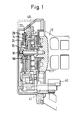
- Fig. 1 einen axialen Teilschnitt der Ausführungsform des Gurtaufrollers; und
- Fig. 2 eine Seitenansicht des in Fig. 1 gezeigten Gurtaufrollers mit aufgebrochen dargestellter Steuerscheibe.
- In einem lasttragenden Gehäuse 10 des Gurtaufrollers ist eine Gurtspule 12 zur Aufnahme des Gurtbandes drehbar gelagert. Der Gurtaufroller ist mit einer notfallsperrenden Sperreinrichtung ausgerüstet, die sowohl gurtbandsensitiv als auch fahrzeugsensitiv aktivierbar ist. Die Sperreinrichtung ist in herkömmlicher Weise ausgebildet und wird daher nicht näher beschrieben. Der Steuermechanismus zur gurtbandsensitiven und fahrzeugsensitiven Ansteuerung der Sperreinrichtung umfaßt eine Steuerscheibe 14, die drehbar auf einem Lagerteil 16 gelagert ist, das durch einen Stift 18 drehfest mit der Gurtspule 12 verbunden ist. Mit der Steuerscheibe 14 sind ein Steuerzahnrad 20, das mit einer Steuerverzahnung 22 versehen ist, und eine als träge Masse wirkende Metallscheibe 24 gekoppelt. Wie aus Fig. 2 ersichtlich ist, ist an dem Lagerteil 16 ferner eine Klinke 26 schwenkbar gelagert. Die Klinke 26, die durch eine Feder 28 in ihre Ruhestellung vorbelastet ist, wirkt mit einer Innenverzahnung eines Ansteuerringes 30 zusammen, durch dessen Drehbewegung die Sperreinrichtung aktivierbar ist.
- Mit der Steuerverzahnung 22 des Steuerzahnrades 20 wirkt in herkömmlicher Weise eine Steuerklinke zusammen, die durch einen Trägheitssensor fahrzeugsensitiv in die Bewegungsbahn der Steuerzähne angehoben wird. Bei Gurtbandabzug tritt dann eine Relativdrehung zwischen Steuerscheibe 14 und Gurtspule auf. Diese Relativdrehung wird über einen Nocken auf die Klinke 26 übertragen, die dann in die Innenverzahnung des Ansteuerringes 30 eingreift und diesen drehfest mit der Gurtspule 12 koppelt. Weiterer Gurtbandabzug führt daher zur Drehung des Ansteuerringes 30 und folglich zur Aktivierung der Sperreinrichtung. Eine Relativdrehung der Steuerscheibe 14 zur Gurtspule 12 tritt aber auch gurtbandsensitiv bei plötzlichem Gurtbandabzug auf, da die Steuerscheibe 14 aufgrund der an sie angekoppelten Metallscheibe 24 und deren Massenträgheit gegenüber der Drehbewegung der Gurtspule zurückbleibt.
- Die bisher beschriebene Ausgestaltung des Gurtaufrollers unterscheidet sich nicht von herkömmlichen Konstruktionen, wie sie beispielsweise in der DE-OS 28 26 286 beschrieben sind.
- Um eine ungewollte Aktivierung der Sperreinrichtung bei plötzlichem Aufrollen des Gurtbandes zu verhindern, ist der Gurtaufroller mit einer Einrichtung versehen, die eine Aktivierung der Sperreinrichtung ab Erreichen eines vorbestimmten Wertes des Außendurchmessers des Gurtbandwickels auf der Gurtspule 12 verhindert. Zu dieser Einrichtung gehört ein Tasthebel 40, der auf einer Achse 42 schwenkbar gelagert ist und einen dem Außendurchmesser des Gurtbandwickels folgenden Schwenkhub um diese Achse 42 ausführt. Dieser Tasthebel 40 ist durch eine Blattfeder 44 elastisch mit einem bogenförmigen Schwenkhebel 46 gekoppelt. Am freien Ende dieses Schwenkhebels 46 ist ein Kupplungszahnrad 48, das aus zwei gleichen, im axialen Abstand voneinander angeordneten Zahnrädern besteht, frei drehbar gelagert. An das Lagerteil 16 angeschlossen ist ein Synchronisationszahnrad 50, dessen Außenverzahnung dem einen der beiden Zahnräder des Kupplungszahnrades 48 gegenüberliegt. Das andere Zahnrad des Kupplungszahnrades 48 liegt einer Außenverzahnung am Außenumfang der Steuerscheibe 14 gegenüber.
- Der Tasthebel 40 bildet mit dem gleichfalls auf der Achse 42 gelagerten Schwenkhebel 46 einen zweiarmigen Hebel, dessen Arme durch die Blattfeder 44 elastisch miteinander gekoppelt sind. Der Schwenkhebel 46 ist im Bereich seiner Lagernabe mit zwei im Abstand voneinander angeordneten Anschlägen 52, 54 versehen, zwischen denen der freie Schenkel der Blattfeder 44 beweglich ist.
- Durch eine ab einem bestimmten Wert des Außendurchmessers des Gurtbandwickels erfolgende, radial auswärts gerichtete Schwenkbewegung des Tasthebels 40 wird der Schwenkhebel 46 zu einer radial einwärts gerichteten Schwenkbewegung veranlaßt, durch welche das Kupplungszahnrad 48 sowohl mit der Verzahnung des Synchronisationszahnrades 50 als auch mit der Verzahnung der Steuerscheibe 14 in Eingriff gebracht wird. Dieser Zustand ist in Fig. 1 dargestellt. Durch das Kupplungszahnrad 48 werden das Synchronisationszahnrad 50 und die Steuerscheibe 14 drehfest miteinander und mit der Gurtspule 12 gekoppelt. Es ist also keine Relativdrehung zwischen Steuerscheibe 14 und Gurtspule möglich, so daß eine Aktivierung der Sperreinrichtung nicht erfolgen kann.
- Bei abnehmendem Außendurchmesser des Gurtbandwickels wird der Tasthebel 40, der elastisch gegen den Gurtbandwickel vorgespannt ist, radial einwärts zurückgeschwenkt, wodurch der Schwenkhebel 46 radial auswärts verschwenkt wird, bis das Kupplungszahnrad 48 außer Eingriff mit dem Synchronisationszahnrad 50 und der Steuerscheibe 14 ist. In diesem Zustand ist die Sperreinrichtung wieder gurtbandsensitiv und fahrzeugsensitiv funktionsfähig.
Claims (5)
Priority Applications (5)
| Application Number | Priority Date | Filing Date | Title |
|---|---|---|---|
| EP90117257A EP0473832B1 (de) | 1990-09-07 | 1990-09-07 | Gurtaufroller mit einer fahrzeugsensitiven und gurtbandsensitiven Sperreinrichtung |
| ES90117257T ES2029782T3 (es) | 1990-09-07 | 1990-09-07 | Dispositivo enrollador de cinturon con un dispositivo de bloqueo sensible al vehiculo y a la correa del cinturon. |
| DE59008732T DE59008732D1 (de) | 1990-09-07 | 1990-09-07 | Gurtaufroller mit einer fahrzeugsensitiven und gurtbandsensitiven Sperreinrichtung. |
| US07/750,326 US5169085A (en) | 1990-09-07 | 1991-08-27 | Safety belt retractor with a vehicle-sensitive and webbing-sensitive blocking mechanism |
| JP3227354A JPH085359B2 (ja) | 1990-09-07 | 1991-09-06 | ベルト引込器 |
Applications Claiming Priority (1)
| Application Number | Priority Date | Filing Date | Title |
|---|---|---|---|
| EP90117257A EP0473832B1 (de) | 1990-09-07 | 1990-09-07 | Gurtaufroller mit einer fahrzeugsensitiven und gurtbandsensitiven Sperreinrichtung |
Publications (2)
| Publication Number | Publication Date |
|---|---|
| EP0473832A1 true EP0473832A1 (de) | 1992-03-11 |
| EP0473832B1 EP0473832B1 (de) | 1995-03-15 |
Family
ID=8204442
Family Applications (1)
| Application Number | Title | Priority Date | Filing Date |
|---|---|---|---|
| EP90117257A Expired - Lifetime EP0473832B1 (de) | 1990-09-07 | 1990-09-07 | Gurtaufroller mit einer fahrzeugsensitiven und gurtbandsensitiven Sperreinrichtung |
Country Status (5)
| Country | Link |
|---|---|
| US (1) | US5169085A (de) |
| EP (1) | EP0473832B1 (de) |
| JP (1) | JPH085359B2 (de) |
| DE (1) | DE59008732D1 (de) |
| ES (1) | ES2029782T3 (de) |
Cited By (2)
| Publication number | Priority date | Publication date | Assignee | Title |
|---|---|---|---|---|
| EP0806326A2 (de) * | 1996-05-06 | 1997-11-12 | TRW Occupant Restraint Systems GmbH | Gurtaufroller für Fahrzeugsicherheitsgurte |
| DE102008009771A1 (de) * | 2008-02-19 | 2009-08-20 | Trw Automotive Gmbh | Gurtaufroller für einen Fahrzeug-Sicherheitsgurt |
Families Citing this family (6)
| Publication number | Priority date | Publication date | Assignee | Title |
|---|---|---|---|---|
| DE4423958A1 (de) * | 1994-07-07 | 1996-01-11 | Trw Repa Gmbh | Gurtaufroller |
| GB2294384B (en) * | 1994-10-26 | 1998-01-14 | Autoliv Dev | A safety belt retractor |
| JP3204911B2 (ja) * | 1996-11-06 | 2001-09-04 | 株式会社東海理化電機製作所 | ウエビング巻取装置 |
| US7090304B2 (en) * | 2004-07-16 | 2006-08-15 | Trw Vehicle Safety Systems Inc. | Retractor having vehicle sensitive sensor disabling mechanism |
| US7637536B2 (en) * | 2006-03-20 | 2009-12-29 | Trw Vehicle Safety Systems Inc. | Retractor having mechanisms for disabling a vehicle sensitive sensor and for preventing webbing withdrawal |
| JP5189383B2 (ja) * | 2008-02-29 | 2013-04-24 | 株式会社東海理化電機製作所 | ウエビング巻取装置 |
Citations (4)
| Publication number | Priority date | Publication date | Assignee | Title |
|---|---|---|---|---|
| US3510085A (en) * | 1967-07-31 | 1970-05-05 | Robbins Seat Belt Co | Emergency locking retractor with disabling means |
| US3711037A (en) * | 1971-04-05 | 1973-01-16 | American Safety Equip | Dead zone mechanism for and inertia locking retractor |
| US4244600A (en) * | 1978-04-18 | 1981-01-13 | Juichiro Takada | Deactivatable locking retractor for vehicle seat belt systems |
| FR2536661A1 (fr) * | 1982-11-29 | 1984-06-01 | Tokai Rika Co Ltd | Enrouleur pour ceinture de securite |
Family Cites Families (6)
| Publication number | Priority date | Publication date | Assignee | Title |
|---|---|---|---|---|
| JPS51135318U (de) * | 1975-04-22 | 1976-11-01 | ||
| DE2826286C2 (de) * | 1978-06-15 | 1989-07-20 | Repa Feinstanzwerk Gmbh, 7071 Alfdorf | Sicherheitsgurtaufrollautomat |
| JPS60155661U (ja) * | 1984-03-28 | 1985-10-17 | 日本精工株式会社 | シ−トベルト装置用リトラクタ |
| JPH0732293Y2 (ja) * | 1988-10-07 | 1995-07-26 | 株式会社東海理化電機製作所 | ウエビング巻取装置 |
| JPH0719931Y2 (ja) * | 1989-01-19 | 1995-05-10 | 株式会社東海理化電機製作所 | ウエビング巻取装置用ロツク機構 |
| JPH0723320Y2 (ja) * | 1990-03-16 | 1995-05-31 | 株式会社東海理化電機製作所 | ウエビング巻取装置 |
-
1990
- 1990-09-07 EP EP90117257A patent/EP0473832B1/de not_active Expired - Lifetime
- 1990-09-07 DE DE59008732T patent/DE59008732D1/de not_active Expired - Fee Related
- 1990-09-07 ES ES90117257T patent/ES2029782T3/es not_active Expired - Lifetime
-
1991
- 1991-08-27 US US07/750,326 patent/US5169085A/en not_active Expired - Lifetime
- 1991-09-06 JP JP3227354A patent/JPH085359B2/ja not_active Expired - Fee Related
Patent Citations (4)
| Publication number | Priority date | Publication date | Assignee | Title |
|---|---|---|---|---|
| US3510085A (en) * | 1967-07-31 | 1970-05-05 | Robbins Seat Belt Co | Emergency locking retractor with disabling means |
| US3711037A (en) * | 1971-04-05 | 1973-01-16 | American Safety Equip | Dead zone mechanism for and inertia locking retractor |
| US4244600A (en) * | 1978-04-18 | 1981-01-13 | Juichiro Takada | Deactivatable locking retractor for vehicle seat belt systems |
| FR2536661A1 (fr) * | 1982-11-29 | 1984-06-01 | Tokai Rika Co Ltd | Enrouleur pour ceinture de securite |
Cited By (4)
| Publication number | Priority date | Publication date | Assignee | Title |
|---|---|---|---|---|
| EP0806326A2 (de) * | 1996-05-06 | 1997-11-12 | TRW Occupant Restraint Systems GmbH | Gurtaufroller für Fahrzeugsicherheitsgurte |
| EP0806326A3 (de) * | 1996-05-06 | 2000-09-27 | TRW Occupant Restraint Systems GmbH & Co. KG | Gurtaufroller für Fahrzeugsicherheitsgurte |
| DE102008009771A1 (de) * | 2008-02-19 | 2009-08-20 | Trw Automotive Gmbh | Gurtaufroller für einen Fahrzeug-Sicherheitsgurt |
| DE102008009771B4 (de) * | 2008-02-19 | 2016-08-11 | Trw Automotive Gmbh | Gurtaufroller für einen Fahrzeug-Sicherheitsgurt |
Also Published As
| Publication number | Publication date |
|---|---|
| JPH085359B2 (ja) | 1996-01-24 |
| DE59008732D1 (de) | 1995-04-20 |
| EP0473832B1 (de) | 1995-03-15 |
| US5169085A (en) | 1992-12-08 |
| ES2029782T1 (es) | 1992-10-01 |
| JPH04230449A (ja) | 1992-08-19 |
| ES2029782T3 (es) | 1995-07-16 |
Similar Documents
| Publication | Publication Date | Title |
|---|---|---|
| EP0627345B1 (de) | Sicherheitsgurtaufroller | |
| EP0709266B1 (de) | Gurtaufroller mit integriertem Gurtstraffer und Energiewandler | |
| DE3876081T2 (de) | Sicherheitsgurt mit spannvorrichtung. | |
| DE2943441C2 (de) | ||
| DE2606293A1 (de) | Vorrichtung zum zurueckziehen und aufrollen eines sicherheitsgurtes | |
| DE3017097A1 (de) | Selbstsperrender gurtaufroller fuer kraftfahrzeug-sicherheitsgurte | |
| EP0382870B1 (de) | Sicherheitsgurtaufroller | |
| DE10321729B4 (de) | Gurtaufroller für einen Fahrzeug-Sicherheitsgurt | |
| WO1997002163A1 (de) | Gurtaufroller für einen sicherheitsgurt | |
| EP0473832B1 (de) | Gurtaufroller mit einer fahrzeugsensitiven und gurtbandsensitiven Sperreinrichtung | |
| EP0472529B1 (de) | Gurtaufroller mit deblockiereinrichtung | |
| EP0717687B1 (de) | Gurtaufroller | |
| EP0625449B2 (de) | Sicherheitsgurtaufrollautomat | |
| EP3286043B1 (de) | Gurtaufroller | |
| EP0646504B1 (de) | Gurtaufroller für Rückhaltesysteme in Fahrzeugen | |
| DE2824864A1 (de) | Gurtaufrollschnellsperrautomat | |
| DE2616906A1 (de) | Selbstarretierende sicherheitsgurt- aufspulvorrichtung | |
| DE3636073A1 (de) | Gurtbandsensitives system mit einer massebehafteten steuerklinke | |
| EP0543044B1 (de) | Gurtaufroller mit Zugentlastung für Sicherheitsgurt-Rückhaltesysteme in Fahrzeugen | |
| DE2326264C2 (de) | Gurtaufroller für einen Fahrzeugsicherheitsgurt | |
| DE3338187C2 (de) | ||
| DE3341289A1 (de) | Doppelseitig sperrbarer gurtaufroller | |
| DE102007019123A1 (de) | Gurtaufroller | |
| DE69917884T2 (de) | Sicherheitsgurtaufroller | |
| EP0543043A1 (de) | Gurtaufroller mit Zugentlastung für Sicherheitsgurt-Rückhaltesysteme in Fahrzeugen |
Legal Events
| Date | Code | Title | Description |
|---|---|---|---|
| PUAI | Public reference made under article 153(3) epc to a published international application that has entered the european phase |
Free format text: ORIGINAL CODE: 0009012 |
|
| AK | Designated contracting states |
Kind code of ref document: A1 Designated state(s): DE ES FR GB IT SE |
|
| EL | Fr: translation of claims filed | ||
| ITCL | It: translation for ep claims filed |
Representative=s name: DR. ING. A. RACHELI & C. |
|
| 17P | Request for examination filed |
Effective date: 19920512 |
|
| 17Q | First examination report despatched |
Effective date: 19930112 |
|
| GRAA | (expected) grant |
Free format text: ORIGINAL CODE: 0009210 |
|
| AK | Designated contracting states |
Kind code of ref document: B1 Designated state(s): DE ES FR GB IT SE |
|
| GBT | Gb: translation of ep patent filed (gb section 77(6)(a)/1977) |
Effective date: 19950309 |
|
| REF | Corresponds to: |
Ref document number: 59008732 Country of ref document: DE Date of ref document: 19950420 |
|
| ITF | It: translation for a ep patent filed | ||
| ET | Fr: translation filed | ||
| REG | Reference to a national code |
Ref country code: ES Ref legal event code: FG2A Ref document number: 2029782 Country of ref document: ES Kind code of ref document: T3 |
|
| PLBE | No opposition filed within time limit |
Free format text: ORIGINAL CODE: 0009261 |
|
| STAA | Information on the status of an ep patent application or granted ep patent |
Free format text: STATUS: NO OPPOSITION FILED WITHIN TIME LIMIT |
|
| RAP2 | Party data changed (patent owner data changed or rights of a patent transferred) |
Owner name: TRW OCCUPANT RESTRAINT SYSTEMS GMBH |
|
| 26N | No opposition filed | ||
| PGFP | Annual fee paid to national office [announced via postgrant information from national office to epo] |
Ref country code: SE Payment date: 19960813 Year of fee payment: 7 |
|
| PG25 | Lapsed in a contracting state [announced via postgrant information from national office to epo] |
Ref country code: SE Free format text: LAPSE BECAUSE OF NON-PAYMENT OF DUE FEES Effective date: 19970908 |
|
| EUG | Se: european patent has lapsed |
Ref document number: 90117257.7 |
|
| PGFP | Annual fee paid to national office [announced via postgrant information from national office to epo] |
Ref country code: GB Payment date: 20010807 Year of fee payment: 12 |
|
| REG | Reference to a national code |
Ref country code: GB Ref legal event code: IF02 |
|
| PG25 | Lapsed in a contracting state [announced via postgrant information from national office to epo] |
Ref country code: GB Free format text: LAPSE BECAUSE OF NON-PAYMENT OF DUE FEES Effective date: 20020907 |
|
| GBPC | Gb: european patent ceased through non-payment of renewal fee |
Effective date: 20020907 |
|
| PGFP | Annual fee paid to national office [announced via postgrant information from national office to epo] |
Ref country code: ES Payment date: 20040923 Year of fee payment: 15 |
|
| PG25 | Lapsed in a contracting state [announced via postgrant information from national office to epo] |
Ref country code: IT Free format text: LAPSE BECAUSE OF NON-PAYMENT OF DUE FEES;WARNING: LAPSES OF ITALIAN PATENTS WITH EFFECTIVE DATE BEFORE 2007 MAY HAVE OCCURRED AT ANY TIME BEFORE 2007. THE CORRECT EFFECTIVE DATE MAY BE DIFFERENT FROM THE ONE RECORDED. Effective date: 20050907 |
|
| PG25 | Lapsed in a contracting state [announced via postgrant information from national office to epo] |
Ref country code: ES Free format text: LAPSE BECAUSE OF NON-PAYMENT OF DUE FEES Effective date: 20050908 |
|
| PGFP | Annual fee paid to national office [announced via postgrant information from national office to epo] |
Ref country code: FR Payment date: 20060906 Year of fee payment: 17 |
|
| PGFP | Annual fee paid to national office [announced via postgrant information from national office to epo] |
Ref country code: DE Payment date: 20060929 Year of fee payment: 17 |
|
| REG | Reference to a national code |
Ref country code: ES Ref legal event code: FD2A Effective date: 20050908 |
|
| PG25 | Lapsed in a contracting state [announced via postgrant information from national office to epo] |
Ref country code: DE Free format text: LAPSE BECAUSE OF NON-PAYMENT OF DUE FEES Effective date: 20080401 |
|
| REG | Reference to a national code |
Ref country code: FR Ref legal event code: ST Effective date: 20080531 |
|
| PG25 | Lapsed in a contracting state [announced via postgrant information from national office to epo] |
Ref country code: FR Free format text: LAPSE BECAUSE OF NON-PAYMENT OF DUE FEES Effective date: 20071001 |