EP0472513A1 - Procédure et disposition dans une section de séchoir à tambours de machine à papier - Google Patents
Procédure et disposition dans une section de séchoir à tambours de machine à papier Download PDFInfo
- Publication number
- EP0472513A1 EP0472513A1 EP91890159A EP91890159A EP0472513A1 EP 0472513 A1 EP0472513 A1 EP 0472513A1 EP 91890159 A EP91890159 A EP 91890159A EP 91890159 A EP91890159 A EP 91890159A EP 0472513 A1 EP0472513 A1 EP 0472513A1
- Authority
- EP
- European Patent Office
- Prior art keywords
- drying
- blow
- box
- paper web
- dryer
- Prior art date
- Legal status (The legal status is an assumption and is not a legal conclusion. Google has not performed a legal analysis and makes no representation as to the accuracy of the status listed.)
- Granted
Links
Images


Classifications
-
- D—TEXTILES; PAPER
- D21—PAPER-MAKING; PRODUCTION OF CELLULOSE
- D21F—PAPER-MAKING MACHINES; METHODS OF PRODUCING PAPER THEREON
- D21F5/00—Dryer section of machines for making continuous webs of paper
- D21F5/02—Drying on cylinders
- D21F5/04—Drying on cylinders on two or more drying cylinders
- D21F5/042—Drying on cylinders on two or more drying cylinders in combination with suction or blowing devices
-
- F—MECHANICAL ENGINEERING; LIGHTING; HEATING; WEAPONS; BLASTING
- F26—DRYING
- F26B—DRYING SOLID MATERIALS OR OBJECTS BY REMOVING LIQUID THEREFROM
- F26B13/00—Machines and apparatus for drying fabrics, fibres, yarns, or other materials in long lengths, with progressive movement
- F26B13/06—Machines and apparatus for drying fabrics, fibres, yarns, or other materials in long lengths, with progressive movement with movement in a sinuous or zig-zag path
- F26B13/08—Machines and apparatus for drying fabrics, fibres, yarns, or other materials in long lengths, with progressive movement with movement in a sinuous or zig-zag path using rollers
Definitions
- the invention relates to a method and an apparatus in a paper machine cylinder dryer in which the web is guided using an upper dryer fabric on the upper dryer cylinders and a lower dryer fabric on the lower dryer cylinders, the dryer fabrics from the surface of the dryer cylinders and from sieve guide rollers arranged in the spaces between them are guided in such a way that the web on the row of the upper drying cylinders has direct drying contact with the surface of the upper drying cylinders by pressing on the upper drying sieve and is accordingly pressed by the lower drying sieve against the surface of the lower drying cylinders, and the web is pressed one is guided to the other row of drying cylinders on a certain route in free train.
- These devices have a wide variety of shapes and locations, in particular in the spaces above the upper and below the lower wire guide rollers between the upper and lower drying cylinders, air being generally sucked out of the screen strand running off the drying cylinder and the wire guide roller.
- the aim of the invention is to eliminate the disadvantages of the known methods and devices and to achieve a simultaneous stabilization of the web and ventilation of the pocket.
- This is achieved according to the invention in the method described at the outset in that at the same time there is a blowing through the wire in the area of the paper web in the part running onto the drying cylinder and suction from the gusset between the drying wire and the wire guide roller.
- the paper web is blown in the part of the cylinder running onto it approximately perpendicular to the paper web and if the suction is induced by a blow directed away from the gusset and oriented essentially perpendicular to the dryer fabric in the area of the wire guide roller.
- the paper web can also be blown in the part of the cylinder running onto the cylinder approximately perpendicular to the paper web and suction can be carried out directly from the gusset. This results in a better control option.
- the invention also relates to a device for a paper machine multi-cylinder dryer, in which two-wire guidance is used, for carrying out the method according to the invention, which is arranged in the interspaces of adjacent drying cylinders above and / or below the screen guide rollers, which interspaces from those over the adjacent drying cylinders running dryer fabrics and the non-wrapped part of these leading guide rollers are limited and which device is characterized in that the device consists of a box which extends over the entire width of the dryer fabric and has openings for blowing out, at the same time a suction of air from the gusset between the drying screen and the screen guide roller.
- a further development of the device according to the invention is characterized in that the box is designed as a one-piece blow box and, if necessary via a control valve, is connected to an air supply, the blow box having blow-out openings and directed towards the paper web in the area of the paper web in the part running onto the drying cylinder is provided in the region of the gusset with discharge openings oriented away from it, optionally with the arrangement of a deflection or guide plate, essentially perpendicular to the dryer fabric in the region of the screen guide roller.
- the box is designed as a two-part blow-suction box and, if necessary, via control valves an air supply and an air discharge is connected, the blow box having approximately perpendicular to the paper web in the area of the paper web in the part running onto the drying cylinder and blowing openings provided in the area of the gusset with suction openings.
- the blow box or the blow-suction box in the lower region of its wall which has the blow-out openings oriented approximately perpendicular to the paper web, is provided with a recess which recesses in order to make the flow in the intermediate space uniform.
- a side cover can be slidably attached to each end face of the blow box and / or the suction box.
- the gaps between the blow box and drying cylinder and / or between the blow and / or suction box and / or wire guide roller can be closed by means of a mechanical seal.
- blowing of the drying wire provided in the method and the device according to the invention, a better pressing of the paper web against the drying cylinder and an increased drying of the paper web running onto the drying cylinder with simultaneous suction from the gusset in the area of the paper web running off the drying cylinder is achieved.
- a blow-out is provided on the upstream side of the drying wire to press the paper web against the drying cylinder and to ventilate the space between the drying wire and paper web
- a blow-out or suction is provided to create a vacuum in the space between the drying cylinder, blowing or To produce suction box, wire guide roller and dryer fabric.
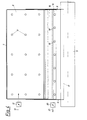
- FIG. 1 shows a side view of a cylinder dryer applying the invention
- FIG. 2 shows a detail from FIG. 1 with a blow box according to the invention
- FIG. 3 shows an arrangement analogous to FIG. 2, but with a combined blow-suction box according to the invention
- Fig. 4 shows the section II of Fig. 3, but with something 3 modified design.
- the multi-cylinder dryer in which the invention is applied, consists of a series of upper drying cylinders 1.1 'etc. and a corresponding series of lower drying cylinders 2.2' etc., which usually have an impermeable peripheral surface and are heated.
- the dryer further consists of a band-shaped upper dryer 4, which is guided by the peripheral surfaces of the drying cylinders 1, 1 'and in the interstices of the guide rollers 5.5'.
- blow boxes 6 Fig. 2
- Blow-suction boxes 6.18 Fig. 1.3
- the blow box 6 is formed in one piece here, ie it consists of a single chamber. It has a mechanical seal 7 at the inlet into the intermediate space, which rests on the adjacent drying cylinder 1. At the lower end of the blow box 6, ie in the vicinity of the wire guide roller 5 or the gusset, there is a blow-out 8 in order to induce a vacuum in the space between the drying cylinder 1, blow box 6, wire guide roller 5 and dryer wire 4 with the paper web 3 resting thereon.
- This blowout 8 is carried out by one or more of a deflection or guide plate 8 'limited, formed from a slot or a series of individual openings (n) blow-out opening (s) 8 ⁇ in a direction which is substantially perpendicular to the dryer fabric 4 in the area between the upper wire guide roller 5 and the upper drying cylinder 1' is oriented.
- displaceable side covers 9 are attached to the end faces of the box 6 in the region of the blow-out opening (s) 8 ⁇ .
- the box 6 has a recess 10.
- blowout 11 On the rising side of the dryer fabric 4 there is a blowout 11 from the blow box 6, etc. approximately perpendicular to the paper web 3 in the area of its part running onto the upper drying cylinder 1 'in order to press the paper web 3 against the drying cylinder 1', as well as to vent the pocket between the dryer fabric 4 and the paper web 3.
- the openings 11 '(Fig. 4) in the blow box 6 are arranged.
- the wire guide roller 5.5 ' is advantageously offset in the direction of the incoming part of the drying wire 4.4' or the paper web 3.
- the directions of rotation of the drying cylinder 1.1 'and the wire guide roller 5 are designated 14.14' and 14 ⁇ ; the running direction of the paper web 3 is from the drying cylinder 1 running 15 and on the drying cylinder 1 'running 16.
- the running direction of the upper dryer 4 is designated in FIGS. 2 and 3 with 16 '.
- the fresh air for the blow box 6 is blown in via the air supply 13 and can be regulated via a control valve 12 and is only shown schematically here.
- FIG. 3 shows a further embodiment of the device according to the invention, the basic features of the first embodiment in FIG. 2 corresponds, but is constructed as a combined blow-suction box 6.18.
- the upper drying cylinders are designated 1.1 'and the indicated lower drying cylinders 2.
- the upper part of the box 6, 18 serves here as a blow box 6, as already shown in FIG. 2, the lower part is designed as a suction box 18. Hiebei air is sucked from the gusset between dryer fabric 4 and wire guide roller 5 in direction 19 via the suction openings 19 'shown in Fig. 4' in the suction box 18 and discharged via a control valve 20 by means of the air discharge 21 (shown schematically).
- a side cover 9 is again provided on the two end faces of the box 6, 18, a seal 17 grazing on the screen guide roller 5, which is attached to the lower part of the suction box 18, being additionally provided here is.
- the blow box 6 is provided with a mechanical seal 7 at the inlet into the intermediate space.
- a recess 10 is provided between the blow box 6 and the suction box 18 in order to equalize the flow in the intermediate space. It goes without saying that the two boxes 6 and 18 can also be combined to form a combined blow-and-suction box separated by an intermediate wall.
- Fig. 4 shows the section I-I of Fig. 3, in which the transverse extension of the box 6.18 is shown.
- the air supply 13 with control valve 12 and the air discharge 21 with control valve 20 are shown schematically here again.
- the sliding side covers 9, the seal 7 on the top and the seal 17 on the bottom can be seen on the sides.
- the corresponding blow-out openings 11 'for the blow-out 11 against the dryer 4 in the region of the second upper drying cylinder 1' and the suction openings 19 'for the suction 19 in the region of the wire guide roller 5 are shown.
- It is also a schematic representation of the suction openings 11 ', 19' which of course also in a different form depending on the conditions, e.g. can be designed as slots or according to the open area to be blown out or the air quantities to be drawn in.
Landscapes
- Engineering & Computer Science (AREA)
- Textile Engineering (AREA)
- Mechanical Engineering (AREA)
- General Engineering & Computer Science (AREA)
- Paper (AREA)
- Drying Of Solid Materials (AREA)
Applications Claiming Priority (3)
| Application Number | Priority Date | Filing Date | Title |
|---|---|---|---|
| AT171890 | 1990-08-21 | ||
| AT1718/90 | 1990-08-21 | ||
| AT171890A AT394740B (de) | 1990-08-21 | 1990-08-21 | Verfahren und vorrichtung in einem schnellaufenden papiermaschinen-mehrzylindertrockner |
Publications (3)
| Publication Number | Publication Date |
|---|---|
| EP0472513A1 true EP0472513A1 (fr) | 1992-02-26 |
| EP0472513B1 EP0472513B1 (fr) | 1995-09-27 |
| EP0472513B2 EP0472513B2 (fr) | 2001-12-05 |
Family
ID=3519508
Family Applications (1)
| Application Number | Title | Priority Date | Filing Date |
|---|---|---|---|
| EP19910890159 Expired - Lifetime EP0472513B2 (fr) | 1990-08-21 | 1991-07-18 | Procédure et disposition dans une section de séchoir à tambours de machine à papier |
Country Status (3)
| Country | Link |
|---|---|
| EP (1) | EP0472513B2 (fr) |
| AT (1) | AT394740B (fr) |
| DE (1) | DE59106580D1 (fr) |
Cited By (6)
| Publication number | Priority date | Publication date | Assignee | Title |
|---|---|---|---|---|
| DE4404726A1 (de) * | 1993-03-11 | 1994-09-15 | Voith Gmbh J M | Zwei-Sieb-Zylindertrockner |
| EP0639668A2 (fr) * | 1993-08-06 | 1995-02-22 | J.M. Voith GmbH | Section de séchage |
| US5477624A (en) * | 1993-03-11 | 1995-12-26 | J. M. Voith Gmbh | Two-wire cylinder dryer |
| EP0756034A2 (fr) * | 1995-07-26 | 1997-01-29 | Voith Sulzer Papiermaschinen GmbH | Procédé et dispositif pour le séchage d'une bande fibreuse |
| EP0824158A2 (fr) * | 1996-08-09 | 1998-02-18 | Voith Sulzer Papiermaschinen GmbH | Dispositif pour le séchage d'une bande fibreuse |
| CN115654904A (zh) * | 2022-10-31 | 2023-01-31 | 安徽常春纸业有限公司 | 一种宣纸烘干装置 |
Families Citing this family (1)
| Publication number | Priority date | Publication date | Assignee | Title |
|---|---|---|---|---|
| CN113623985A (zh) * | 2021-08-17 | 2021-11-09 | 马鞍山晨晖新材料科技有限公司 | 一种装饰用纸生产用烘干装置 |
Citations (4)
| Publication number | Priority date | Publication date | Assignee | Title |
|---|---|---|---|---|
| US3668787A (en) * | 1970-09-01 | 1972-06-13 | Valmet Oy | Ventilating device for a multicylinder drier |
| US4481723A (en) * | 1980-12-01 | 1984-11-13 | Valmet Oy | Paper machine multiple cylinder dryer |
| JPS60194193A (ja) * | 1984-03-13 | 1985-10-02 | 製紙技術研究組合 | 多筒式抄紙機ドライヤのポケツトベンチレ−タ |
| US4899463A (en) * | 1987-09-29 | 1990-02-13 | Valmet Paper Machinery Inc. | Method and device in a cylinder dryer of a paper machine |
-
1990
- 1990-08-21 AT AT171890A patent/AT394740B/de not_active IP Right Cessation
-
1991
- 1991-07-18 EP EP19910890159 patent/EP0472513B2/fr not_active Expired - Lifetime
- 1991-07-18 DE DE59106580T patent/DE59106580D1/de not_active Expired - Fee Related
Patent Citations (4)
| Publication number | Priority date | Publication date | Assignee | Title |
|---|---|---|---|---|
| US3668787A (en) * | 1970-09-01 | 1972-06-13 | Valmet Oy | Ventilating device for a multicylinder drier |
| US4481723A (en) * | 1980-12-01 | 1984-11-13 | Valmet Oy | Paper machine multiple cylinder dryer |
| JPS60194193A (ja) * | 1984-03-13 | 1985-10-02 | 製紙技術研究組合 | 多筒式抄紙機ドライヤのポケツトベンチレ−タ |
| US4899463A (en) * | 1987-09-29 | 1990-02-13 | Valmet Paper Machinery Inc. | Method and device in a cylinder dryer of a paper machine |
Cited By (9)
| Publication number | Priority date | Publication date | Assignee | Title |
|---|---|---|---|---|
| DE4404726A1 (de) * | 1993-03-11 | 1994-09-15 | Voith Gmbh J M | Zwei-Sieb-Zylindertrockner |
| US5477624A (en) * | 1993-03-11 | 1995-12-26 | J. M. Voith Gmbh | Two-wire cylinder dryer |
| EP0639668A2 (fr) * | 1993-08-06 | 1995-02-22 | J.M. Voith GmbH | Section de séchage |
| EP0639668A3 (fr) * | 1993-08-06 | 1996-02-07 | Voith Gmbh J M | Section de séchage. |
| EP0756034A2 (fr) * | 1995-07-26 | 1997-01-29 | Voith Sulzer Papiermaschinen GmbH | Procédé et dispositif pour le séchage d'une bande fibreuse |
| EP0756034A3 (fr) * | 1995-07-26 | 1998-01-28 | Voith Sulzer Papiermaschinen GmbH | Procédé et dispositif pour le séchage d'une bande fibreuse |
| EP0824158A2 (fr) * | 1996-08-09 | 1998-02-18 | Voith Sulzer Papiermaschinen GmbH | Dispositif pour le séchage d'une bande fibreuse |
| EP0824158A3 (fr) * | 1996-08-09 | 1999-01-27 | Voith Sulzer Papiermaschinen GmbH | Dispositif pour le séchage d'une bande fibreuse |
| CN115654904A (zh) * | 2022-10-31 | 2023-01-31 | 安徽常春纸业有限公司 | 一种宣纸烘干装置 |
Also Published As
| Publication number | Publication date |
|---|---|
| DE59106580D1 (de) | 1995-11-02 |
| EP0472513B2 (fr) | 2001-12-05 |
| EP0472513B1 (fr) | 1995-09-27 |
| AT394740B (de) | 1992-06-10 |
| ATA171890A (de) | 1991-11-15 |
Similar Documents
| Publication | Publication Date | Title |
|---|---|---|
| DE4406846C1 (de) | Vorrichtung zum Trocknen von bedruckten Bogen oder Bahnen in Druckmaschinen | |
| DE3138133C2 (de) | Entwässerungseinheit für Langsieb-Papiermaschinen | |
| DE3790947C2 (de) | Verfahren und Vorrichtung für eine Taschenventilation in der Trockenpartie einer Papiermaschine, insbesondere für schnellaufende Papiermaschinen | |
| AT392991B (de) | Trockenpartie fuer eine maschine zur herstellung oder verarbeitung von faserbahnen, insbesondere papierbahnen | |
| DE2355397A1 (de) | Trockenzylindergruppe in einem mehrzylindertrockner fuer eine materialbahn, insbesondere fuer papier | |
| DE4018074A1 (de) | Vorrichtung zum reinigen eines umlaufenden papiermaschinensiebes | |
| EP0787854A1 (fr) | Dispositif pour guider une bande fibreuse dans une section de séchage à toile unique | |
| DE3818600C2 (fr) | ||
| DE3630570C2 (de) | Verfahren und Vorrichtung in einem Papiermaschinen-Zylindertrockner mit Zweisiebführung | |
| DE69016536T2 (de) | Vorrichtung in der Trockenpartie einer Papiermaschine. | |
| DE4013485C2 (de) | Verfahren und Vorrichtung zur Effektivierung der Bahnendaufführung in einer Papiermaschinentrockenpartie | |
| AT394870B (de) | Trocknungsvorrichtung | |
| DE3831280A1 (de) | Verfahren und vorrichtung in einem papiermaschinen-zylindertrockner | |
| DE19807511C2 (de) | Trocken- und/oder Fixiervorrichtung | |
| AT394740B (de) | Verfahren und vorrichtung in einem schnellaufenden papiermaschinen-mehrzylindertrockner | |
| AT394063B (de) | Trocknungsvorrichtung | |
| DE4139708B4 (de) | Blas- und Lüftungsvorrichtung für eine umgekehrte Zylindergruppe einer Papiermaschinentrockenpartie | |
| DE4009287B4 (de) | Verfahren und Vorrichtung zum Trocknen einer feuchten Papierbahn in einer Papiermaschinen-Trockenpartie | |
| DE4407405A1 (de) | Trockenpartie | |
| DE10024296B4 (de) | Maschine zur Herstellung einer Materialbahn | |
| DE4035985B4 (de) | Absaugverfahren und Absaugvorrichtung in einer Papiermaschine | |
| DE604269C (de) | Verfahren und Vorrichtung zum Trocknen von Geweben | |
| AT131153B (de) | Verfahren und Vorrichtung zum Trocknen von bedruckten oder sonstigen feuchten Stoff- oder Papierbahnen. | |
| EP0692569B1 (fr) | Procédé et dispositif dans un séchoir à cylindres d'une machine à papier ayant deux toiles de séchage | |
| DE3707612C2 (de) | Luftleitkasten mit einer Einrichtung zur Führung des Überführstreifens durch die Trockenpartie einer Papiermaschine |
Legal Events
| Date | Code | Title | Description |
|---|---|---|---|
| PUAI | Public reference made under article 153(3) epc to a published international application that has entered the european phase |
Free format text: ORIGINAL CODE: 0009012 |
|
| AK | Designated contracting states |
Kind code of ref document: A1 Designated state(s): BE CH DE DK FR IT LI NL |
|
| 17P | Request for examination filed |
Effective date: 19920803 |
|
| 17Q | First examination report despatched |
Effective date: 19940425 |
|
| GRAA | (expected) grant |
Free format text: ORIGINAL CODE: 0009210 |
|
| AK | Designated contracting states |
Kind code of ref document: B1 Designated state(s): BE CH DE DK FR IT LI NL |
|
| PG25 | Lapsed in a contracting state [announced via postgrant information from national office to epo] |
Ref country code: IT Free format text: LAPSE BECAUSE OF FAILURE TO SUBMIT A TRANSLATION OF THE DESCRIPTION OR TO PAY THE FEE WITHIN THE PRE;WARNING: LAPSES OF ITALIAN PATENTS WITH EFFECTIVE DATE BEFORE 2007 MAY HAVE OCCURRED AT ANY TIME BEFORE 2007. THE CORRECT EFFECTIVE DATE MAY BE DIFFERENT FROM THE ONE RECORDED.SCRIBED TIME-LIMIT Effective date: 19950927 Ref country code: NL Free format text: LAPSE BECAUSE OF FAILURE TO SUBMIT A TRANSLATION OF THE DESCRIPTION OR TO PAY THE FEE WITHIN THE PRESCRIBED TIME-LIMIT Effective date: 19950927 Ref country code: BE Effective date: 19950927 Ref country code: DK Effective date: 19950927 |
|
| REF | Corresponds to: |
Ref document number: 59106580 Country of ref document: DE Date of ref document: 19951102 |
|
| ET | Fr: translation filed | ||
| NLV1 | Nl: lapsed or annulled due to failure to fulfill the requirements of art. 29p and 29m of the patents act | ||
| PLBQ | Unpublished change to opponent data |
Free format text: ORIGINAL CODE: EPIDOS OPPO |
|
| PLBI | Opposition filed |
Free format text: ORIGINAL CODE: 0009260 |
|
| PLBF | Reply of patent proprietor to notice(s) of opposition |
Free format text: ORIGINAL CODE: EPIDOS OBSO |
|
| PG25 | Lapsed in a contracting state [announced via postgrant information from national office to epo] |
Ref country code: CH Effective date: 19960731 Ref country code: LI Effective date: 19960731 |
|
| 26 | Opposition filed |
Opponent name: VALMET CORPORATION Effective date: 19960626 |
|
| PLBF | Reply of patent proprietor to notice(s) of opposition |
Free format text: ORIGINAL CODE: EPIDOS OBSO |
|
| REG | Reference to a national code |
Ref country code: CH Ref legal event code: PL |
|
| RDAH | Patent revoked |
Free format text: ORIGINAL CODE: EPIDOS REVO |
|
| APAC | Appeal dossier modified |
Free format text: ORIGINAL CODE: EPIDOS NOAPO |
|
| APAE | Appeal reference modified |
Free format text: ORIGINAL CODE: EPIDOS REFNO |
|
| APAC | Appeal dossier modified |
Free format text: ORIGINAL CODE: EPIDOS NOAPO |
|
| APAC | Appeal dossier modified |
Free format text: ORIGINAL CODE: EPIDOS NOAPO |
|
| PLAW | Interlocutory decision in opposition |
Free format text: ORIGINAL CODE: EPIDOS IDOP |
|
| PUAH | Patent maintained in amended form |
Free format text: ORIGINAL CODE: 0009272 |
|
| STAA | Information on the status of an ep patent application or granted ep patent |
Free format text: STATUS: PATENT MAINTAINED AS AMENDED |
|
| 27A | Patent maintained in amended form |
Effective date: 20011205 |
|
| AK | Designated contracting states |
Kind code of ref document: B2 Designated state(s): BE CH DE DK FR IT LI NL |
|
| ET3 | Fr: translation filed ** decision concerning opposition | ||
| APAH | Appeal reference modified |
Free format text: ORIGINAL CODE: EPIDOSCREFNO |
|
| PGFP | Annual fee paid to national office [announced via postgrant information from national office to epo] |
Ref country code: DE Payment date: 20070719 Year of fee payment: 17 |
|
| PGFP | Annual fee paid to national office [announced via postgrant information from national office to epo] |
Ref country code: FR Payment date: 20070710 Year of fee payment: 17 |
|
| PG25 | Lapsed in a contracting state [announced via postgrant information from national office to epo] |
Ref country code: DE Free format text: LAPSE BECAUSE OF NON-PAYMENT OF DUE FEES Effective date: 20090203 |
|
| REG | Reference to a national code |
Ref country code: FR Ref legal event code: ST Effective date: 20090331 |
|
| PG25 | Lapsed in a contracting state [announced via postgrant information from national office to epo] |
Ref country code: FR Free format text: LAPSE BECAUSE OF NON-PAYMENT OF DUE FEES Effective date: 20080731 |