EP0471488A2 - Verkettetes Drucken mit beabstandeten Druckbereichen - Google Patents
Verkettetes Drucken mit beabstandeten Druckbereichen Download PDFInfo
- Publication number
- EP0471488A2 EP0471488A2 EP91307153A EP91307153A EP0471488A2 EP 0471488 A2 EP0471488 A2 EP 0471488A2 EP 91307153 A EP91307153 A EP 91307153A EP 91307153 A EP91307153 A EP 91307153A EP 0471488 A2 EP0471488 A2 EP 0471488A2
- Authority
- EP
- European Patent Office
- Prior art keywords
- printing
- arrays
- lines
- color
- Prior art date
- Legal status (The legal status is an assumption and is not a legal conclusion. Google has not performed a legal analysis and makes no representation as to the accuracy of the status listed.)
- Withdrawn
Links
- 238000003491 array Methods 0.000 title claims abstract description 73
- 239000003086 colorant Substances 0.000 claims abstract description 79
- 239000000976 ink Substances 0.000 description 41
- 239000010432 diamond Substances 0.000 description 30
- 238000000151 deposition Methods 0.000 description 10
- 229910003460 diamond Inorganic materials 0.000 description 9
- 238000000034 method Methods 0.000 description 8
- 230000008021 deposition Effects 0.000 description 7
- 239000012943 hotmelt Substances 0.000 description 4
- 239000011159 matrix material Substances 0.000 description 4
- 230000000740 bleeding effect Effects 0.000 description 3
- 230000007547 defect Effects 0.000 description 3
- 238000010586 diagram Methods 0.000 description 3
- 239000000203 mixture Substances 0.000 description 3
- 230000003287 optical effect Effects 0.000 description 3
- 239000007787 solid Substances 0.000 description 3
- 238000010420 art technique Methods 0.000 description 2
- 102100025752 CASP8 and FADD-like apoptosis regulator Human genes 0.000 description 1
- 101710100501 CASP8 and FADD-like apoptosis regulator Proteins 0.000 description 1
- 239000002131 composite material Substances 0.000 description 1
- 238000010276 construction Methods 0.000 description 1
- 230000001419 dependent effect Effects 0.000 description 1
- 230000000694 effects Effects 0.000 description 1
- 230000004886 head movement Effects 0.000 description 1
- 238000003384 imaging method Methods 0.000 description 1
- 230000007246 mechanism Effects 0.000 description 1
- 238000000926 separation method Methods 0.000 description 1
- 238000001228 spectrum Methods 0.000 description 1
- 229920001169 thermoplastic Polymers 0.000 description 1
- 239000004416 thermosoftening plastic Substances 0.000 description 1
- 230000000007 visual effect Effects 0.000 description 1
- XLYOFNOQVPJJNP-UHFFFAOYSA-N water Substances O XLYOFNOQVPJJNP-UHFFFAOYSA-N 0.000 description 1
Images


Classifications
-
- B—PERFORMING OPERATIONS; TRANSPORTING
- B41—PRINTING; LINING MACHINES; TYPEWRITERS; STAMPS
- B41J—TYPEWRITERS; SELECTIVE PRINTING MECHANISMS, i.e. MECHANISMS PRINTING OTHERWISE THAN FROM A FORME; CORRECTION OF TYPOGRAPHICAL ERRORS
- B41J2/00—Typewriters or selective printing mechanisms characterised by the printing or marking process for which they are designed
- B41J2/485—Typewriters or selective printing mechanisms characterised by the printing or marking process for which they are designed characterised by the process of building-up characters or image elements applicable to two or more kinds of printing or marking processes
- B41J2/505—Typewriters or selective printing mechanisms characterised by the printing or marking process for which they are designed characterised by the process of building-up characters or image elements applicable to two or more kinds of printing or marking processes from an assembly of identical printing elements
- B41J2/5056—Typewriters or selective printing mechanisms characterised by the printing or marking process for which they are designed characterised by the process of building-up characters or image elements applicable to two or more kinds of printing or marking processes from an assembly of identical printing elements using dot arrays providing selective dot disposition modes, e.g. different dot densities for high speed and high-quality printing, array line selections for multi-pass printing, or dot shifts for character inclination
-
- B—PERFORMING OPERATIONS; TRANSPORTING
- B41—PRINTING; LINING MACHINES; TYPEWRITERS; STAMPS
- B41J—TYPEWRITERS; SELECTIVE PRINTING MECHANISMS, i.e. MECHANISMS PRINTING OTHERWISE THAN FROM A FORME; CORRECTION OF TYPOGRAPHICAL ERRORS
- B41J2/00—Typewriters or selective printing mechanisms characterised by the printing or marking process for which they are designed
- B41J2/005—Typewriters or selective printing mechanisms characterised by the printing or marking process for which they are designed characterised by bringing liquid or particles selectively into contact with a printing material
- B41J2/01—Ink jet
- B41J2/21—Ink jet for multi-colour printing
- B41J2/2132—Print quality control characterised by dot disposition, e.g. for reducing white stripes or banding
-
- B—PERFORMING OPERATIONS; TRANSPORTING
- B41—PRINTING; LINING MACHINES; TYPEWRITERS; STAMPS
- B41J—TYPEWRITERS; SELECTIVE PRINTING MECHANISMS, i.e. MECHANISMS PRINTING OTHERWISE THAN FROM A FORME; CORRECTION OF TYPOGRAPHICAL ERRORS
- B41J19/00—Character- or line-spacing mechanisms
- B41J19/14—Character- or line-spacing mechanisms with means for effecting line or character spacing in either direction
- B41J19/142—Character- or line-spacing mechanisms with means for effecting line or character spacing in either direction with a reciprocating print head printing in both directions across the paper width
Definitions
- This invention relates to color printing wherein a color image is formed by printing repeated sets of lines with one or more colors by a print head scanning a print medium. It particularly relates to color printing with interlacing of black and/or the three conventional subtractive primary colors, cyan, magenta and yellow using spaced linear arrays of print nozzles.
- the preferred method and embodiment for practicing the present invention is particularly directed to an ink jet printer wherein a print head scans over a print medium, most typically a sheet of paper or transparent film, by shuttling back and forth across the sheet (bi-directional movement) or by moving continuously along the sheet in one direction while the sheet is held against a rotating drum.
- Images are formed by selectively and serially depositing ink drops of primary or base colors at uniformly spaced address locations disposed in uniformly spaced rows to form a dot-matrix image. Variations in color may be achieved by depositing one or more ink drops of more than one size or color at an address to form picture elements or pixels.
- the present invention is equally applicable to any printing process wherein a print head travels along parallel lines relative to a print medium to form a desired final image, whether the image be graphic or textual.
- the term "print” is considered to include the general situation where a print element or nozzle addresses an ink drop location, whether or not ink is deposited.
- the size of the drop may vary and even the number of drops of a given color that are deposited at a particular address can vary.
- Hewlett-Packard Labs has demonstrated the latter with drop-on-demand (DOD) thermal inkjets; and Hertz, at the Lund Institute in Sweden, has also demonstrated this with continuous ink jets. Printing with drops of several selected sizes (for gray scale control at each address) was demonstrated by MRIT with air assisted DOD jets in the early 1980s.
- Print heads are known that contain a nozzle for each color of printing for a single line. These nozzles are positioned adjacent to a sheet of paper. A print head carriage then moves relative to the paper one line at a time depositing ink pixels at selected pixel locations until the entire image area has been scanned.
- ink jets have more than one nozzle to print a given color on each address of a given line.
- One nozzle is used to print ink at its maximum optical density, and the other(s) to print ink at some diluted dye concentration(s) so that more than one optical density level of the color can be obtained at each address.
- Some early printers also had the nozzles aligned normal to the scan direction for scanning spaced- apart parallel lines. Thus, colors are always laid down in the same sequence, and one color has time to dry before the next one is printed on top of it.
- Hirata et al. in U. S. Patent No. 4,554,556 entitled “Color Plotter”, disclose printing a dot with all three colors at once, or sequentially during a single scan.
- Tozaki in U. S. patent No. 4,580,150 entitled “Recording Apparatus”, discloses a print array in which two nozzles are used to print one color in a limited image region and then a single nozzle is used to print a second color over the same region.
- a form of line interlacing of color-band printing is disclosed by Hillmann et al. in U. S. patent No. 4,728,968 entitled "Arrangement of Discharge Openings in a Printhead of a Multi-Color Ink Printer".
- the array is moved one half the draft-quality line spacing to print higher resolution images. This requires a different print medium advance after alternate scans.
- each color dries before the next color is deposited, and the colors are always deposited in the same sequence.
- all the colors are deposited during each scan and the sequence of deposition is reversed for the two scan directions.
- Line interlacing means that adjacent lines of dots of the same color are printed in sequential scans of the pen. For example, lines 1, 3, 5, etc., might be printed in one scan, while lines 2, 4, 6, etc., would be printed in the next scan. In a high speed printer, it is desirable to print in both scan directions. With line interlacing, any printing errors and hence image defects that might be dependent on the scan direction would be generated at the spatial frequency of the inverse line spacing and should be less noticeable than if they were generated at a lower spatial frequency.
- inks are used in drop-on-demand printing. These are primarily water-based inks, oil-based inks, and hot-melt or thermoplastic inks. The latter inks are preferred, due to the intensity of the colors and the fact that they can be used on many different print mediums.
- a discussion of printing with colored inks, generally, and with hot-melt inks, in particular, is discussed by Howard et al. in U. S. Patent No. 4,741,930 entitled "Ink Jet Color Printing Method".
- dots of hot-melt ink that have not set are deposited continuously together or on top of each other, they mix. When they mix, the resultant color is different than it is if the first dot solidifies before the second dot is deposited.
- the color laydown sequence is also important. Different sequences produce color flue shifts and appearances of surface irregularities.
- each of the multicolor overlay sequences should always be the same regardless of scan direction. If this is not possible, then the next best thing is to have the sequences alternate on adjacent lines so that the spatial frequency of the hue variations will be as high as possible and will be averaged out as much as possible by the visual system of an observer.
- a limitation on the configuration of arrays for printing interlaced lines is the physical size requirements of the ink jets.
- nozzles By varying the line of an array of nozzles in the direction of scan motion of the print head, nozzles can be positioned for printing on any lines desired. As the effective line spacing of the array is reduced, the length of the array increases in the scan direction.
- the present invention provides a method and apparatus for substantially reducing color image irregularities while minimizing the number of address lines spanned by the array.
- the preferred embodiment of the present invention is usable in a serial, dot-matrix, print-on-demand inkjet head described in European Patent Application No 90 311119.3 (corresponding to US Patent Application Serial No 07/419, 367 ).
- This disclosure describes an ink jet printer for printing with band and line interlacing of a single color such as would be used for monochromatic graphic or text images. This application is incorporated herein by reference.
- the present application further improves on the above application and on the known prior art by providing improved color imaging.
- the present invention provides an apparatus for printing an image on a print medium along print lines having centers spaced a predetermined interline distance apart.
- An apparatus for such an image includes a print head operating relative to a print medium and has first and second linear arrays with a predetermined number of printing elements. Also included is a print head driver for moving the print head relative to a print medium in a first direction for addressing simultaneously a number of print lines corresponding to the number of printing elements in the two linear arrays.
- the first array addresses only even-numbered lines
- the second array addresses only odd-numbered lines.
- the print driver moves the print head relative to the print medium in a second direction transverse to the first direction an advance distance equal to the sum of the widths of the lines of each color printed in both arrays. This results in the second array addressing lines not addressed by the first array and all lines on the image area are addressed by the two arrays.
- the two arrays are spaced apart in the second or advance direction so that no adjacent lines are addressed at the same time during movement of the print head in the first direction.
- the first and second arrays are for printing three colors, with each array having an equal number of print elements for printing each color.
- the third and fourth linear arrays of print elements have the same number and spacing of print elements as the first and second arrays for printing a fourth color.
- the third and fourth arrays are spaced in the first direction from the first and second arrays, respectively, with the print elements in the third array addressing even-numbered lines and the print elements in the fourth array addressing odd-numbered lines.
- the third and fourth arrays are also offset in the second direction relative to the first and second arrays by an offset distance equal to an integer times the advance distance.
- the first and second arrays are sufficiently separated in the second direction so that the printing elements in the third and fourth arrays that are offset in the second direction address lines not spanned by the first and second arrays.
- This array structure allows the individual ink jets to be clustered together as close as possible while satisfying the requirements for line and band interlacing. Further, by assigning the primary colors to separate bands of nozzles within each array, the same deposition sequence of colors to produce secondary colors is provided, including the fourth color, which is typically black. With two of the arrays being used for black-only printing, text can be printed more rapidly than would otherwise be possible.
- Printer 10 receives scan data from a data source 12. This data defines the colors to be printed at each pixel location on a predetermined image area of a print medium.
- the data is fed into a printer driver 13 that controls operation of a print engine 14.
- Control includes feeding formatted data to a print head 16, the movement of which is provided by a carriage controlled by a carriage servo 18.
- Control signals are exchanged between the printer driver, the carriage servo, and other mechanical systems, not shown, such as a print medium mover to provide coordinated movement of the print head relative to the print medium during printing.
- a detailed description of a printer 10 usable for practicing this invention, is as described in previously referenced European Patent Application No 90 311119.3. That application also describes well known prior art techniques for interlaced printing in a single color.
- FIG. 2 an exemplary print head face 20 usable in printer 10 is shown positioned next to a print medium 22, such as a sheet of suitable paper.
- Face 20 includes a first array 24 of individual black-ink-printing nozzles 26, and a second array 28 of color-ink-printing nozzles 30. It will be understood that black, white and various colors of the color spectrum in between are all considered colors. Face 20, and associated print head 16 thus prints using a plurality of colors. Printing occurs when the print head moves or scans horizontally, as viewed in Fig. 2 back and forth from left to right and right to left. This horizontal movement is also referred to as movement in a first or scan direction.
- Array 24 comprises sets 32, 33 and 34.
- Array 28 comprises sets 36, 37 and 38.
- Array 24 is positioned vertically (in the direction of the print medium movement, which direction is also referred to as the second or advance direction) above array 28 so that sets 32 and 38 print on the same lines during a single scan of the print head.
- the six sets of nozzles thus print five sets 40, 41, 42, 43 and 44 of lines in a single scan.
- ink colors are represented by a geometric symbol.
- a triangle represents black
- a square, a diamond, and a circle each represent one of three other colors, such as the three conventional subtractive primary colors, magenta, cyan and yellow. Other colors could also be used.
- a column 46 of triangles on print medium 22 indicates the lines addressed for printing by the nozzles in array 24.
- a column 48 of squares, diamonds, and circles indicates the lines addressed by the nozzles in array 28. There is a mix of colors in column 48 that will be more fully discussed with reference to Fig. 3. Between scans the print medium is shifted or advanced upward relative to the arrays, the width D equivalent of four print lines, or the width of one set of print lines.
- the lines of the top two set of black nozzles print alternate lines as illustrated by the arrows associated with the triangle symbols.
- the arrows indicate which nozzles print during scan movement in the direction shown by the arrows.
- the array configuration provides for printing with black ink after the primary colors are printed. This is important where the inks do not dry quickly or where there is bleeding of the colors. By printing black last, a constant sequence of deposition is provided relative to the other colors. Also, when printing only black text, array 28 is disabled and all nozzles in array 24 are used so that printing can take place three times as fast as during color image printing.
- Fig. 2 shows an "ideal" embodiment in that black is always printed on a given line after all of the other colors have been printed. (Note: there is no occasion when black is ever printed at the same address as any of the other colors. Further, there is never an occasion when all of the three subtractive colors are printed at the same address.)
- This "ideal" embodiment extends the nozzle arrays in the vertical direction more than would be preferred.
- An alternative embodiment, shown in dashed lines in Fig. 2 has the black array 24' shifted so that there is a black nozzle 26' on every line there is a color nozzle. This is the most compact embodiment in the vertical direction, and in this sense, is also an "ideal" embodiment.
- Faces 20 and 20' are shown for purposes of illustration.
- Each array in the intended commercial embodiment, as shown in Fig. 15, is four times the size of arrays 24 and 28. That is, there are 48 black-printing nozzles, and 48 multicolor-printing nozzles. Thus, instead of sets of 4 nozzles, there are sets of 16 nozzles.
- Figs. 3 - 13 illustrate various arrangements that satisfy various ones of the desired features of a color printing system discussed earlier. In these figures, time is considered to progress from left to right. Thus, symbols shown on the same print line are considered to overlay each other, with the sequence of deposition occurring as determined by the deposition timing identified by sequential scans 1 - 3 or 4.
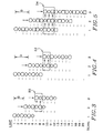
- Figs. 3 and 4 illustrate two configurations for printing two colors with color interlacing.
- Fig. 3 shows two colors represented as circles and diamonds that simply alternate within a set of printing elements for printing line-by-line alternating colors.
- the number N of nozzles must be odd.
- Fig. 3 there are three nozzles of each color and the print head is shifted a distance D equal to the width of three lines between scans.
- the resulting overlay sequence is represented in the outlined region 50. It can be seen that the overlay sequence alternates with every line, except for the band edges.
- This method and configuration provide for band and line interlacing.
- Line interlacing results because each color is printed on only odd numbered lines in one scan and only on even numbered lines in the next scan, since the incremental distance change D is equivalent to the width of an odd number of lines.
- FIG. 4 An alternative two-color printing configuration is shown in Fig. 4.
- the head color array is made up of two sets of four nozzles, with the nozzles alternating colors within each set, but with the placement of colors in each set reversed. For instance, during scan 1, the color represented by a circle prints on lines 1 and 3 in the first set and on lines 6 and 8 in the second set. As can be seen, the color in one set always prints on the odd lines and the same color in the other set always prints on the even lines.
- the overlay sequence alternates every line. Considering that the band of circles encompasses eight lines, and that for diamonds encompasses six lines, the circles have near perfect band interlacing, whereas the diamonds have partial band interlacing. Also, it can be seen that the diamonds are printed on two consecutive lines during each scan. Otherwise line interlacing is also achieved.
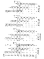
- Figs. 5 - 10 show different head configurations for printing three colors, such as the primary subtractive colors, cyan, magenta and yellow.
- Fig. 5 illustrates the case where the three colors alternate within a single set of nozzles.
- N the number of nozzles of each color, must not be an integer multiple of three.
- each line is only addressed once, and the overlay sequence of each color pair does not alternate perfectly line-by-line.
- the order of circle/square, square/diamond and diamond/circle repeats every two out of three lines. However, there is both band and line interlacing of each color.
- Fig. 6 The configuration shown in Fig. 6 is the same as that illustrated in Fig. 2 for the jets that print in color.
- three sets of four nozzles are used, with each set printing alternating lines of two colors. Each set prints a different one of the three pairs of colors: square/circle, diamond/square and circle/diamond.
- lines 9 and 10 are the first lines to be overlaid by all three sets of nozzles.
- the resulting overlay sequence is represented in the outlined region 56.
- the ink drop locations in line 9 are addressed ("printed") first by the nozzle printing the color represented by the circle, followed by the nozzle printing a diamond and then by a nozzle printing a square.
- the circle is printed before both the diamond and the square
- the diamond is printed before the square.
- no more than two colors are printed at a single ink drop address location.
- Printing all three at one address results in "composite” or "three-color” black which always has a noticeable, dingy and repugnant hue. This arises because the subtractive primary colors are not ideal. Thus, it is better to print a single drop of pure black.
- line 10 the diamond is printed before the square and the circle, and the square is printed before the circle. This alternating pattern applies to all of the lines printed, as could be illustrated by continuing to draw columns for scans 4 and beyond.
- the printing method illustrated in Fig. 6, and the print element array associated with it, provide for band interlacing of squares and diamonds, and line interlacing of all three colors.
- the bands of squares and diamonds each span thirty-two lines in this embodiment.
- This array also provides a constant deposition order for one pair of colors (diamonds and squares), and provides alternative deposition orders for the other two pairs of colors (circles and diamonds, and circles and squares) on adjacent lines.
- each of print head sets 36, 37 and 38 have a single color, as is conventionally known.
- the first set is circles
- the second set is diamonds
- the third set is squares.
- each color is neither band interlaced nor line interlaced.
- Fig. 8 shows yet another embodiment, this one having the first two print element sets 36 and 37 alternating between circles and diamonds, and the third set 38 all squares.
- this embodiment provides both line and band interlacing for two colors (circles and diamonds) and a constant color overlay sequence for two of the color pairs (diamonds and squares, and circles and squares).
- the third color (squares) is neither line nor band interlaced.
- Fig. 9 the set 37 of printing elements printing a single color, diamonds in this case, is in the middle.
- the first and third sets 36 and 38 alternate colors represented by squares and circles. As shown by outlined region 62, this configuration provides alternating overlay sequences for all three color pair combinations. However, one of the colors --diamonds-- is not line interlaced. There is no band interlacing at all.
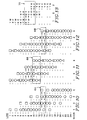
- Fig. 10 The last three-color configuration is illustrated in Fig. 10. This configuration diverts from the previous configurations in which every line within the range of the print array is printed (addressed). This configuration requires four sets of nozzles. The two end sets each print a different single color on alternating lines. The two intermediate sets print alternating lines of two different color pairs. Four scans are required in order to have each line addressed by each of the colors, as is illustrated in outlined region 64.
- This configuration though it requires a larger print head (4N-1 rather than 3N-1 address lines), provides a constant overlay sequence for all three colors. Further, there is band interlacing and line interlacing for all three colors.
- Figs. 11 - 13 illustrate configurations for printing four colors.
- Fig. 11 there is a single set with the colors alternating in each set. If N, the number of nozzles per color, is even then the print head must be incremented on alternating scans by N-1 and N+1 lines. For N odd, regular increments of N lines after each scan provides printing of each color once on every line.
- N 3 in the figure.
- four scans are required in order to have every line addressed by every color. This results in three increments per band, which averages out any anomalies due to band edges. There also is complete line interlacing. However, the overlay sequences vary between not alternating at all to alternating every second line. The results are therefore inconsistent.
- Fig. 12 illustrates a preferred arrangement for printing four colors, where all four colors are given an equal number of nozzles.
- a first set of four nozzles alternates between triangles and squares, the second set between diamonds and squares, the third set between diamonds and circles, and the last set between triangles and circles, as shown.
- the respective colors are assigned so that they print on even lines in one set and on odd lines in the other set in which they appear.
- a comparison on this configuration with the three-color configuration of Fig. 10 will show that they are identical as to the colors represented by squares, diamonds and circles.
- the triangles have been added where there were nozzle omissions in Fig. 10.
- the overlay sequence is the same for the three colors of Fig. 10.
- the sequences alternate every line for the combinations with the fourth color. This scheme would therefore be useful where black is assigned to the triangle positions and the three primary colors are assigned the other three symbol positions. This configuration produces line and partial band interlacing.
- Fig. 13 illustrates a configuration in which the four colors are treated as two sets of two colors.
- Each pair of colors, here yellow (Y) and black (K), and magenta (M) and cyan (C) are given the same array configuration as the two colors of Fig. 4.
- Y yellow
- K black
- M magenta
- C cyan
- one two-color array could be positioned vertically, as represented here, to form a single line of both arrays so that there is a delay between the printing of color pairs.
- the print head in such an arrangement is, however, much less compact.
- Fig. 13 The configuration of Fig. 13 is particularly desirable for hot-melt ink, where the inks combine when placed on top of or next to drops of ink that are not set. Since black is not applied to a spot that has another color, it is never combined on the same spot with other colors.
- the main color combinations alternate line-by-line except for yellow and magenta, which produce red, as shown by outlined region 70. This color pair stays the same on alternate two-line intervals. Since the eye is much less sensitive to red than to green, stripes or other anomalies will be less apparent.
- magenta and cyan which produce blue, could also be used for this inconsistent color-overlay sequence pair. It is advantageous having cyan and yellow on different lines to allow the spots of ink to set between scans in order to produce a more consistent green.
- the nozzles could be vertically separated by twice the interline spacing so that no two color dots within the same array print on adjacent lines. This, however, doubles the size of the array.
- Fig. 2 The arrays of a print head illustrated in Fig. 2 becomes very wide when made with ink jets that are essentially identical in construction.
- a design has been developed in which channels extend from spaced locations to the line of nozzles in order to achieve the close spacing.
- An alternative design, that achieves the same inkjet density while using ink jets having an ink reservoir close to the nozzle or ink orifice is shown in Fig. 14.
- Each jet includes a reservoir 82 of inkwith a piezoelectricelement for driving the ink through an offset channel 84 to a nozzle or orifice 86.
- the jets are placed as shown adjacent one of two lines 88 and 90 forming spaced nozzle arrays 92 and 94.
- D 1 is the spacing between the centers of adjacent printed lines, or the effective width of a single line.
- D 2 is the distance between the parallel nozzle lines 88 and 90.
- D 3 is the offset on nozzles in one line relative to the other line.
- X 1 is the distance in the advance direction of movement of the print medium relative to the print head between scans.
- the Greek symbol 0 is the angle of lines 88 and 90 relative to the scan direction represented by arrow 96.
- X 1 (2N i + 1)D 1 , where N 1 is an integer.
- D 1 3.33... mils.
- the ink jets have a diameter of approximately 4 mm, or 157.5 mils.
- the distance between orifices in line 88 or 90 is approximately 67 mils or the width of 20 lines. With the spacing in the advance direction of the distance of two lines, this results in a 1:10 slope of the lines, or an angle 0 of 5.7°.
- the distance D 2 is 232.09 mils, resulting in a closest value for X i of 234.50 mils.
- a value ofX 1 236.66... is equivalent to the width of 71 lines.
- Fig. 15 shows the resulting layout of a print head face 100 including the nozzle configuration described with reference to Fig. 14.
- Arrow 112 shows the direction of print medium advance relative to the print head, and arrow 114 shows the direction of print head movement during scanning.
- Arrays 102 and 104 print black only, and arrays 106 and 108 print the three colors.
- Array 106 thus contains subarrays 116, 118 and 120 for printing bands of first, second and third colors, respectively.
- array 108 contains subarrays 122, 124 and 126 for printing the same colors in preferably the same respective order.
- array 102 is offset in the advance direction relative to array 106, as is array 104 relative to array 108, a distance equal to the width of 16 lines. This results in the capability of printing black dots on lines not printed by arrays 106 and 108 during each scan. When only black is printed, such as for text, arrays 106 and 108 are disabled and the entire arrays 102 and 104 are used.
- Line interlacing is provided, since only alternate lines are printed during each scan, even when only black is printed. This also assures there is no bleeding of colors between adjacent lines.
- Band interlacing is provided, since one array prints about halfway into the band printed by the other array, for each color. By band printing the colors, there also is constant sequence of overlay of the primary colors, regardless of the scan direction, resulting in constant hues or tones for each overlay combination. Additionally, by printing only alternate lines and only one color per line during each scan, the ink has time to dry or set before a second color is deposited on it.
Landscapes
- Engineering & Computer Science (AREA)
- Quality & Reliability (AREA)
- Ink Jet (AREA)
- Color, Gradation (AREA)
Applications Claiming Priority (2)
| Application Number | Priority Date | Filing Date | Title |
|---|---|---|---|
| US567027 | 1990-08-14 | ||
| US07/567,027 US5079571A (en) | 1990-05-25 | 1990-08-14 | Interlaced printing using spaced print arrays |
Publications (2)
| Publication Number | Publication Date |
|---|---|
| EP0471488A2 true EP0471488A2 (de) | 1992-02-19 |
| EP0471488A3 EP0471488A3 (en) | 1992-10-28 |
Family
ID=24265437
Family Applications (1)
| Application Number | Title | Priority Date | Filing Date |
|---|---|---|---|
| EP19910307153 Withdrawn EP0471488A3 (en) | 1990-08-14 | 1991-08-02 | Interlaced printing using spaced print arrays |
Country Status (3)
| Country | Link |
|---|---|
| US (1) | US5079571A (de) |
| EP (1) | EP0471488A3 (de) |
| JP (1) | JP2651879B2 (de) |
Cited By (12)
| Publication number | Priority date | Publication date | Assignee | Title |
|---|---|---|---|---|
| EP0566119A2 (de) * | 1992-04-17 | 1993-10-20 | Rohm Co., Ltd. | Verfahren zum Betrieb eines Tintenstrahldruckkopfes |
| EP0622211A2 (de) * | 1993-04-30 | 1994-11-02 | Hewlett-Packard Company | Tintenstrahldruckverfahren auf Kunststoffaufzeichnungsmaterial |
| EP0622212A2 (de) * | 1993-04-30 | 1994-11-02 | Hewlett-Packard Company | Bild-Druckverfahren |
| EP0665114A2 (de) * | 1994-01-31 | 1995-08-02 | Tektronix, Inc. | Farbstrahldruckkopfanordnung und verkettetes Druckverfahren |
| EP0745484A1 (de) * | 1995-05-31 | 1996-12-04 | Océ Graphics France S.A. | Drucken von Bildern mittels eines Punktmatrixdruckers |
| EP0754553A2 (de) * | 1995-07-19 | 1997-01-22 | Canon Kabushiki Kaisha | Verfahren und Vorrichtung zur Herstellung von Farbfiltern |
| EP0756933A2 (de) * | 1995-08-01 | 1997-02-05 | Canon Kabushiki Kaisha | Verfahren und Apparat zum Herstellen eines Farbfilters, diesen Farbfilter verwendende Anzeigevorrichtung und elektronische Apparatur mit dieser Anzeigevorrichtung |
| US5717447A (en) * | 1991-08-19 | 1998-02-10 | Rohm Co., Ltd. | Method of driving ink jet printing head |
| EP0933219A1 (de) * | 1998-01-28 | 1999-08-04 | Toshiba Tec Kabushiki Kaisha | Bilder bildendes Gerät |
| US6157461A (en) * | 1997-10-27 | 2000-12-05 | Hewlett-Packard Company | Method of generating randomized masks to improve image quality on a printing medium |
| US8459778B2 (en) | 2011-08-25 | 2013-06-11 | Electronics For Imaging, Inc. | Reduced gloss banding through low ink volume deposition per print pass |
| US8684511B2 (en) | 2011-08-25 | 2014-04-01 | Electronics For Imaging, Inc. | Ink jet UV pinning for control of gloss |
Families Citing this family (35)
| Publication number | Priority date | Publication date | Assignee | Title |
|---|---|---|---|---|
| CA2049571C (en) * | 1990-10-19 | 2004-01-13 | Kent D. Vincent | High definition thermal ink-jet printer |
| US6106102A (en) * | 1992-05-01 | 2000-08-22 | Hewlett-Packard Company | Odd number of passes, odd number of advances, and separated-diagonal-line masking, in liquid-ink printers |
| JP3155832B2 (ja) * | 1992-09-25 | 2001-04-16 | キヤノン株式会社 | インクジェット記録方法および記録装置 |
| US5699093A (en) * | 1992-10-07 | 1997-12-16 | Hslc Technology Associates Inc | Ink jet print head |
| JP3227284B2 (ja) * | 1992-10-30 | 2001-11-12 | キヤノン株式会社 | インクジェット記録方法およびインクジェット記録ヘッド |
| US5522016A (en) * | 1993-05-13 | 1996-05-28 | Dataproducts Corporation | Digitally controlled printing |
| US5455610A (en) * | 1993-05-19 | 1995-10-03 | Xerox Corporation | Color architecture for an ink jet printer with overlapping arrays of ejectors |
| US5485183A (en) * | 1993-06-30 | 1996-01-16 | Dataproducts Corporation | Interlaced dot-on-dot printing |
| US5724079A (en) * | 1994-11-01 | 1998-03-03 | Internaional Business Machines Corporation | Combined black and color ink jet printing |
| US5805183A (en) * | 1994-11-10 | 1998-09-08 | Lasermaster Corporation | Ink jet printer with variable advance interlacing |
| US5625390A (en) * | 1995-01-30 | 1997-04-29 | Tektronix, Inc. | Pairing of ink drops on a print medium |
| JP3424708B2 (ja) * | 1995-06-07 | 2003-07-07 | ブラザー工業株式会社 | ドットマトリクス印字システム |
| US5793392A (en) * | 1995-06-13 | 1998-08-11 | Tschida; Mark J. | Printing apparatus and method |
| JP3382438B2 (ja) * | 1995-12-20 | 2003-03-04 | キヤノン株式会社 | 記録装置 |
| US5757400A (en) * | 1996-02-01 | 1998-05-26 | Spectra, Inc. | High resolution matrix ink jet arrangement |
| JPH1067125A (ja) * | 1996-08-28 | 1998-03-10 | Oki Data:Kk | インクジェット記録装置及び制御方法 |
| US6149263A (en) * | 1996-11-13 | 2000-11-21 | Ricoh Company, Ltd. | Ink jet recording apparatus capable of increasing a monochrome print speed without causing ink supply shortage to an image |
| JPH10235906A (ja) * | 1997-02-25 | 1998-09-08 | Brother Ind Ltd | 記録ヘッドおよび画像データ記録方法 |
| DE19810849C2 (de) * | 1998-03-13 | 2000-05-18 | Tally Computerdrucker Gmbh | Schaltung zum Ansteuern von in Zeilenrichtung (5) relativ zum Aufzeichnungsträger bewegten Düsenköpfen der Piezo-Bauart für Tindendrucker |
| EP1057633B1 (de) * | 1998-12-24 | 2008-09-03 | Seiko Epson Corporation | Aufzeichnungskopf eines tintenstrahltypes |
| US6328418B1 (en) * | 1999-08-11 | 2001-12-11 | Hitachi Koki Co., Ltd | Print head having array of printing elements for printer |
| US6257699B1 (en) | 1999-10-13 | 2001-07-10 | Xerox Corporation | Modular carriage assembly for use with high-speed, high-performance, printing device |
| US6238037B1 (en) | 2000-02-07 | 2001-05-29 | Lexmark International, Inc. | Method of multi-dot interlace printing |
| US6513905B2 (en) * | 2000-03-31 | 2003-02-04 | Encad, Inc. | Nozzle cross talk reduction in an ink jet printer |
| US20050151785A1 (en) * | 2004-01-10 | 2005-07-14 | Xerox Corporation. | Drop generating apparatus |
| US7222937B2 (en) * | 2004-01-10 | 2007-05-29 | Xerox Corporation | Drop generating apparatus |
| KR100694119B1 (ko) * | 2005-06-01 | 2007-03-12 | 삼성전자주식회사 | 프린트헤드 유닛 및 이를 구비한 칼라 잉크젯 프린터 |
| US7967407B2 (en) * | 2006-02-03 | 2011-06-28 | R.R. Donnelley | Use of a sense mark to control a printing system |
| US8753026B2 (en) | 2007-06-29 | 2014-06-17 | R.R. Donnelley & Sons Company | Use of a sense mark to control a printing system |
| WO2010065697A1 (en) * | 2008-12-03 | 2010-06-10 | Videojet Technologies Inc. | An inkjet printing system and method |
| US9098903B2 (en) * | 2009-07-21 | 2015-08-04 | R.R. Donnelley & Sons Company | Systems and methods for detecting alignment errors |
| CN104553313B (zh) * | 2013-10-23 | 2017-02-08 | 北大方正集团有限公司 | 打印图像数据处理方法及装置 |
| WO2016169602A1 (en) * | 2015-04-23 | 2016-10-27 | Hewlett-Packard Development Company, L.P. | Printing systems |
| US10370214B2 (en) | 2017-05-31 | 2019-08-06 | Cryovac, Llc | Position control system and method |
| CN110865779B (zh) * | 2019-11-15 | 2024-02-09 | 深圳市汉森软件股份有限公司 | 单喷头多色打印的数据提取方法、装置、设备及存储介质 |
Citations (4)
| Publication number | Priority date | Publication date | Assignee | Title |
|---|---|---|---|---|
| US4864328A (en) * | 1988-09-06 | 1989-09-05 | Spectra, Inc. | Dual mode ink jet printer |
| EP0376596A2 (de) * | 1988-12-27 | 1990-07-04 | Hewlett-Packard Company | Bildelementstellendruckvorrichtung mittels eines mehrere Düsen pro Bildelement oder Bildelementspalte verwendenden Tintenstrahldruckers |
| US4967203A (en) * | 1989-09-29 | 1990-10-30 | Hewlett-Packard Company | Interlace printing process |
| GB2238023A (en) * | 1989-11-09 | 1991-05-22 | Dataproducts Corp | Colour ink-jet printing methods |
Family Cites Families (17)
| Publication number | Priority date | Publication date | Assignee | Title |
|---|---|---|---|---|
| US3864696A (en) * | 1971-10-26 | 1975-02-04 | Rca Corp | Printing apparatus |
| US3925790A (en) * | 1974-04-25 | 1975-12-09 | Rca Corp | Image generator having a plurality of marker units operated in a predetermined sequence to inhibit the formation of patterns |
| US4112469A (en) * | 1977-04-21 | 1978-09-05 | The Mead Corporation | Jet drop copying apparatus |
| US4131898A (en) * | 1977-09-15 | 1978-12-26 | The Mead Corporation | Interlacing recorder |
| US4232324A (en) * | 1978-06-05 | 1980-11-04 | International Business Machines Corporation | Apparatus for arranging scanning heads for interlacing |
| JPS58138656A (ja) * | 1982-02-12 | 1983-08-17 | Canon Inc | 記録装置 |
| US4528576A (en) * | 1982-04-15 | 1985-07-09 | Canon Kabushiki Kaisha | Recording apparatus |
| JPS58194575A (ja) * | 1982-05-11 | 1983-11-12 | Ricoh Co Ltd | カラ−プロツタ |
| US4593295A (en) * | 1982-06-08 | 1986-06-03 | Canon Kabushiki Kaisha | Ink jet image recording device with pitch-shifted recording elements |
| JPS59115853A (ja) * | 1982-12-23 | 1984-07-04 | Sharp Corp | インクジエツト記録装置 |
| US4680596A (en) * | 1984-08-02 | 1987-07-14 | Metromedia Company | Method and apparatus for controlling ink-jet color printing heads |
| US4741930A (en) * | 1984-12-31 | 1988-05-03 | Howtek, Inc. | Ink jet color printing method |
| US4714936A (en) * | 1985-06-24 | 1987-12-22 | Howtek, Inc. | Ink jet printer |
| US4728968A (en) * | 1985-08-30 | 1988-03-01 | Siemens Aktiengesellschaft | Arrangement of discharge openings in a printhead of a multi-color ink printer |
| US4812859A (en) * | 1987-09-17 | 1989-03-14 | Hewlett-Packard Company | Multi-chamber ink jet recording head for color use |
| US4965593A (en) * | 1989-07-27 | 1990-10-23 | Hewlett-Packard Company | Print quality of dot printers |
| US4978971A (en) * | 1989-11-06 | 1990-12-18 | Tektronix, Inc. | Method and apparatus for reformatting print data |
-
1990
- 1990-08-14 US US07/567,027 patent/US5079571A/en not_active Expired - Lifetime
-
1991
- 1991-08-02 EP EP19910307153 patent/EP0471488A3/en not_active Withdrawn
- 1991-08-14 JP JP3228749A patent/JP2651879B2/ja not_active Expired - Fee Related
Patent Citations (4)
| Publication number | Priority date | Publication date | Assignee | Title |
|---|---|---|---|---|
| US4864328A (en) * | 1988-09-06 | 1989-09-05 | Spectra, Inc. | Dual mode ink jet printer |
| EP0376596A2 (de) * | 1988-12-27 | 1990-07-04 | Hewlett-Packard Company | Bildelementstellendruckvorrichtung mittels eines mehrere Düsen pro Bildelement oder Bildelementspalte verwendenden Tintenstrahldruckers |
| US4967203A (en) * | 1989-09-29 | 1990-10-30 | Hewlett-Packard Company | Interlace printing process |
| GB2238023A (en) * | 1989-11-09 | 1991-05-22 | Dataproducts Corp | Colour ink-jet printing methods |
Cited By (29)
| Publication number | Priority date | Publication date | Assignee | Title |
|---|---|---|---|---|
| US5717447A (en) * | 1991-08-19 | 1998-02-10 | Rohm Co., Ltd. | Method of driving ink jet printing head |
| US5483268A (en) * | 1992-04-17 | 1996-01-09 | Rohm Co., Ltd. | Method for driving ink jet print head |
| EP0566119A3 (en) * | 1992-04-17 | 1994-05-25 | Rohm Co Ltd | Method for driving ink jet print head |
| EP0566119A2 (de) * | 1992-04-17 | 1993-10-20 | Rohm Co., Ltd. | Verfahren zum Betrieb eines Tintenstrahldruckkopfes |
| SG84477A1 (en) * | 1993-04-30 | 2001-11-20 | Hewlett Packard Co | Maximum-diagonal print mask and multipass printing modes, for high quality and high through put with liquid-base inks |
| US5677716A (en) * | 1993-04-30 | 1997-10-14 | Hewlett-Packard Company | Maximum-diagonal print mask and multipass printing modes, for high quality and high throughput with liquid-base inks |
| EP0622212A3 (de) * | 1993-04-30 | 1995-03-15 | Hewlett Packard Co | Bild-Druckverfahren. |
| EP0622211A3 (de) * | 1993-04-30 | 1996-03-20 | Hewlett Packard Co | Tintenstrahldruckverfahren auf Kunststoffaufzeichnungsmaterial. |
| EP0622211A2 (de) * | 1993-04-30 | 1994-11-02 | Hewlett-Packard Company | Tintenstrahldruckverfahren auf Kunststoffaufzeichnungsmaterial |
| EP0622212A2 (de) * | 1993-04-30 | 1994-11-02 | Hewlett-Packard Company | Bild-Druckverfahren |
| EP0665114A3 (de) * | 1994-01-31 | 1995-12-13 | Tektronix Inc | Farbstrahldruckkopfanordnung und verkettetes Druckverfahren. |
| EP0665114A2 (de) * | 1994-01-31 | 1995-08-02 | Tektronix, Inc. | Farbstrahldruckkopfanordnung und verkettetes Druckverfahren |
| EP0745484A1 (de) * | 1995-05-31 | 1996-12-04 | Océ Graphics France S.A. | Drucken von Bildern mittels eines Punktmatrixdruckers |
| FR2734759A1 (fr) * | 1995-05-31 | 1996-12-06 | Oce Graphics France | Procede d'impression d'images par points au moyen d'une tete d'impression multipoints, en plusieurs passes |
| US5995715A (en) * | 1995-05-31 | 1999-11-30 | Oce-Technologies B.V. | Method and apparatus for reducing strip effect caused by printers |
| US6874883B1 (en) | 1995-07-19 | 2005-04-05 | Canon Kabushiki Kaisha | Color filter manufacturing method and apparatus, ink jet device, color filter, display device, and apparatus having display device |
| EP0754553A3 (de) * | 1995-07-19 | 1997-10-08 | Canon Kabushiki Kaisha | Verfahren und Vorrichtung zur Herstellung von Farbfiltern, Tintenstrahlvorrichtung, Farbfilter, Anzeigevorrichtung und Apparat mit Anzeigevorrichtung |
| US7381444B2 (en) | 1995-07-19 | 2008-06-03 | Canon Kabushiki Kaisha | Color filter manufacturing method and apparatus, ink-jet device, color filter, display device, and apparatus having display device |
| US7270846B2 (en) | 1995-07-19 | 2007-09-18 | Canon Kabushiki Kaisha | Color filter manufacturing method and apparatus, ink-jet device, color filter, display device, and apparatus having display device |
| EP0754553A2 (de) * | 1995-07-19 | 1997-01-22 | Canon Kabushiki Kaisha | Verfahren und Vorrichtung zur Herstellung von Farbfiltern |
| US6604821B1 (en) | 1995-08-01 | 2003-08-12 | Canon Kabushiki Kaisha | Method and apparatus for manufacturing color filter, display device using the color filter, and electronic equipment comprising the display device |
| EP0756933A2 (de) * | 1995-08-01 | 1997-02-05 | Canon Kabushiki Kaisha | Verfahren und Apparat zum Herstellen eines Farbfilters, diesen Farbfilter verwendende Anzeigevorrichtung und elektronische Apparatur mit dieser Anzeigevorrichtung |
| EP0756933A3 (de) * | 1995-08-01 | 1997-08-13 | Canon Kk | Verfahren und Apparat zum Herstellen eines Farbfilters, diesen Farbfilter verwendende Anzeigevorrichtung und elektronische Apparatur mit dieser Anzeigevorrichtung |
| US6157461A (en) * | 1997-10-27 | 2000-12-05 | Hewlett-Packard Company | Method of generating randomized masks to improve image quality on a printing medium |
| US6213585B1 (en) | 1998-01-28 | 2001-04-10 | Toshiba Tec Kabushiki Kaisha | Image formation apparatus |
| EP0933219A1 (de) * | 1998-01-28 | 1999-08-04 | Toshiba Tec Kabushiki Kaisha | Bilder bildendes Gerät |
| US8459778B2 (en) | 2011-08-25 | 2013-06-11 | Electronics For Imaging, Inc. | Reduced gloss banding through low ink volume deposition per print pass |
| US8672451B2 (en) | 2011-08-25 | 2014-03-18 | Electronics For Imaging, Inc. | Reduced gloss banding through low ink volume deposition per print pass |
| US8684511B2 (en) | 2011-08-25 | 2014-04-01 | Electronics For Imaging, Inc. | Ink jet UV pinning for control of gloss |
Also Published As
| Publication number | Publication date |
|---|---|
| JP2651879B2 (ja) | 1997-09-10 |
| EP0471488A3 (en) | 1992-10-28 |
| JPH04250070A (ja) | 1992-09-04 |
| US5079571A (en) | 1992-01-07 |
Similar Documents
| Publication | Publication Date | Title |
|---|---|---|
| US5079571A (en) | Interlaced printing using spaced print arrays | |
| US5059984A (en) | Method and apparatus for interlaced multicolor printing | |
| US5075689A (en) | Bidirectional hot melt ink jet printing | |
| US4864328A (en) | Dual mode ink jet printer | |
| US4593295A (en) | Ink jet image recording device with pitch-shifted recording elements | |
| JP3066384B2 (ja) | インタレース印刷方法 | |
| EP0526186B1 (de) | Tintenstrahlaufzeichnungsverfahren | |
| US4855752A (en) | Method of improving dot-on-dot graphics area-fill using an ink-jet device | |
| JP2994015B2 (ja) | プリント方法 | |
| EP0865927B1 (de) | Vorrichtung und Verfahren zum Drucken unter Verwendung von Mehrfachdüsengruppen | |
| EP0539157B1 (de) | Mehrfarbentintenstrahlaufzeichnungsgerät | |
| US5485183A (en) | Interlaced dot-on-dot printing | |
| JPH10278317A (ja) | インクジェット式記録装置 | |
| EP0899681B1 (de) | Druckverfahren mit Tintenstrahdrucker mit verbesserter horizontalen Auflösung | |
| EP0497614B1 (de) | Verfahren zum verschachtelten Hochgeschwindigkeitsdruck Gemäss der Abtastrichtung der Druckkopfachse | |
| US6315388B1 (en) | Draft printing | |
| JP3015209B2 (ja) | 多色インクを使用したインクジェット記録方法 | |
| EP0661870A1 (de) | Verfahren und Vorrichtung für Flüssigtintenbilderdruck mit schwarzer Tinte und Farbtinten | |
| JPH06336016A (ja) | インクジェット記録方法及び記録装置 | |
| JP2002178545A (ja) | インクジェット・カラー印刷方法およびプリンタ | |
| JPH0376226B2 (de) | ||
| JP2592847B2 (ja) | カラーインクジエツト記録方法 | |
| JPS58194540A (ja) | 記録装置 | |
| EP1208991B1 (de) | Farbtintenstrahldruckmethode und Drucker | |
| JP3070352B2 (ja) | インクジェット記録装置の印字処理方式 |
Legal Events
| Date | Code | Title | Description |
|---|---|---|---|
| PUAI | Public reference made under article 153(3) epc to a published international application that has entered the european phase |
Free format text: ORIGINAL CODE: 0009012 |
|
| AK | Designated contracting states |
Kind code of ref document: A2 Designated state(s): DE FR GB IT |
|
| PUAL | Search report despatched |
Free format text: ORIGINAL CODE: 0009013 |
|
| AK | Designated contracting states |
Kind code of ref document: A3 Designated state(s): DE FR GB IT |
|
| STAA | Information on the status of an ep patent application or granted ep patent |
Free format text: STATUS: THE APPLICATION IS DEEMED TO BE WITHDRAWN |
|
| 18D | Application deemed to be withdrawn |
Effective date: 19930302 |