EP0470620A2 - Verfahren zur Herstellung von Formkörpern aus siliciuminfiltriertem Siliciumcarbid - Google Patents
Verfahren zur Herstellung von Formkörpern aus siliciuminfiltriertem Siliciumcarbid Download PDFInfo
- Publication number
- EP0470620A2 EP0470620A2 EP91113342A EP91113342A EP0470620A2 EP 0470620 A2 EP0470620 A2 EP 0470620A2 EP 91113342 A EP91113342 A EP 91113342A EP 91113342 A EP91113342 A EP 91113342A EP 0470620 A2 EP0470620 A2 EP 0470620A2
- Authority
- EP
- European Patent Office
- Prior art keywords
- silicon
- rings
- sisic
- blank
- carrier
- Prior art date
- Legal status (The legal status is an assumption and is not a legal conclusion. Google has not performed a legal analysis and makes no representation as to the accuracy of the status listed.)
- Granted
Links
Images

Classifications
-
- C—CHEMISTRY; METALLURGY
- C04—CEMENTS; CONCRETE; ARTIFICIAL STONE; CERAMICS; REFRACTORIES
- C04B—LIME, MAGNESIA; SLAG; CEMENTS; COMPOSITIONS THEREOF, e.g. MORTARS, CONCRETE OR LIKE BUILDING MATERIALS; ARTIFICIAL STONE; CERAMICS; REFRACTORIES; TREATMENT OF NATURAL STONE
- C04B35/00—Shaped ceramic products characterised by their composition; Ceramics compositions; Processing powders of inorganic compounds preparatory to the manufacturing of ceramic products
- C04B35/515—Shaped ceramic products characterised by their composition; Ceramics compositions; Processing powders of inorganic compounds preparatory to the manufacturing of ceramic products based on non-oxide ceramics
- C04B35/56—Shaped ceramic products characterised by their composition; Ceramics compositions; Processing powders of inorganic compounds preparatory to the manufacturing of ceramic products based on non-oxide ceramics based on carbides or oxycarbides
- C04B35/565—Shaped ceramic products characterised by their composition; Ceramics compositions; Processing powders of inorganic compounds preparatory to the manufacturing of ceramic products based on non-oxide ceramics based on carbides or oxycarbides based on silicon carbide
- C04B35/573—Shaped ceramic products characterised by their composition; Ceramics compositions; Processing powders of inorganic compounds preparatory to the manufacturing of ceramic products based on non-oxide ceramics based on carbides or oxycarbides based on silicon carbide obtained by reaction sintering or recrystallisation
Definitions
- the invention relates to a method for siliconizing porous shaped bodies made of silicon carbide / carbon using a dense packing of porous rings made of silicon infiltrated silicon carbide as infiltration aids.
- silicon carbide shaped bodies are infiltrated with silicon, zones with a particularly high silicon content, so-called siliconized sheets, are often formed, as well as components that are undersilicated. Both lead to committee.
- the silicon carbide / carbon molded body is infiltrated via a porous silicon carbide plate which is provided with a coating of boron nitride, silicon carbide and carbon. Below the silicon carbide plate and possibly to the side of it there is (before heating the furnace) piece of elemental silicon.
- plate-shaped SiSiC infiltration aids has disadvantages. If the silicon, which is located between the fuel plates and the silicon carbide plates used as infiltration aids, has melted, the plates sink due to the force of gravity through the (specifically lighter silicon) and displace it. Due to the surface tension, silicon mirrors of up to 5 mm in height can form on the fuel plate.
- the sinking of the SiSiC plates into the molten silicon increases the silicon level. This can lead to the components coming into direct contact with the molten silicon when the plates are too low. This can lead to uneven infiltration and the appearance of stress in the component, which is often manifested by the formation of cracks. The resulting cracks fill with silicon and are visible in the component as siliconized sheets. This effect could be prevented by reducing the amount of silicon per fuel plate or by increasing the thickness of the silicon carbide plates. However, both options reduce the economics of the process.
- the described method using SiSiC plates is also used to siliconize moldings with a flat contact surface.
- a plate-shaped base has the disadvantage that the siliconized molded body sticks to it with its flat contact surface and is therefore difficult to remove.
- a method is known in which a first annular blank made of 70 to 95% silicon carbide, the rest of carbon, is siliconized in contact with a second annular compact made of 87 to 97% silicon, the rest of carbon.
- the second compact produces a highly porous, brittle matrix made of silicon carbide, which can guide the excess silicon well into the first silicon carbide / carbon blank.
- the disadvantage is that the brittle base can only be used once and then has to be removed. However, it is favorable that the base and the shaped body are geometrically adapted to one another. It was therefore the task of specifying a method in which, after the infiltration process, the moldings can be easily detached without being damaged by flaking and the infiltration aid being usable repeatedly.
- the invention is based on the knowledge that the contact surfaces of the blank to be siliconized with the carrier, i.e. the infiltration aid should be as small as possible.
- a process has now been found for siliconizing porous shaped bodies made of silicon carbide / carbon, in which a mixture of silicon carbide powder, organic binder and optionally carbon is deformed to form a green body, the binder of the green body is coked in a non-oxidizing atmosphere at about 1000 ° C. and the blank obtained is siliconized by the action of molten silicon, the blank obtained resting on a porous SiSiC carrier which is in contact with the lower part of the liquid silicon and the arrangement of the SiSiC carrier and the molded body obtained is cooled after the siliconization has ended.
- a dense packing of porous rings made of SiSiC is used as the carrier, which pa are arranged parallel to each other and vertically on a silicon-loaded graphite fuel plate impermeable to liquid silicon.
- rings can also carry a single blank. If the shaped body has at least one flat outer surface with which it lies on the rings, it is advantageous if the rings have the same height.
- the common contact area between the carrier rings and the siliconized blank placed thereon (and thus the difficulties in removing the blank after the siliconizing) can be reduced in that the ring surfaces are rounded at the top.
- the rings are closed at the bottom and silicon is also filled into the interior of the containers thus created.
- the spherical diameter should be larger than the inner diameter of the ring and a spherical blank should be in contact with a carrier ring.
- rings can be used which are chamfered on the inside, so that the balls are in surface contact with the carrier rings.
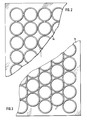
- Figures 2 and 3 show two tight packs of individual tubes (1), which are placed on a graphite plate (15).
- the speed at which the molten silicon travels through the SiSiC rings can be controlled by the amount and size of the pore diameter in the aid. This effect is already described (for the siliconization of a green body) in Special Ceramics 5, 1970, in connection with FIG. 6.
- a reduction in the pore diameter slows down the silicon flow, and an enlargement accelerates it.
- the size of the pore radii depends on the silicon carbide grains used in the manufacture of the kiln furniture (rings). Coarse grain sizes (e.g. F 230) result in large pores, fine grain sizes (e.g. F 1200) result in small pores. Through a suitable selection of the silicon carbide grains, a large range of pore radius distributions can thus be set if necessary.
Landscapes
- Chemical & Material Sciences (AREA)
- Engineering & Computer Science (AREA)
- Ceramic Engineering (AREA)
- Structural Engineering (AREA)
- Manufacturing & Machinery (AREA)
- Materials Engineering (AREA)
- Chemical Kinetics & Catalysis (AREA)
- Organic Chemistry (AREA)
- Ceramic Products (AREA)
- Silicon Polymers (AREA)
- Preparation Of Compounds By Using Micro-Organisms (AREA)
- Peptides Or Proteins (AREA)
- Pharmaceuticals Containing Other Organic And Inorganic Compounds (AREA)
- Carbon And Carbon Compounds (AREA)
Abstract
Description
- Die Erfindung betrifft ein Verfahren zum Silizieren von porösen Formkörpern aus Siliziumcarbid/Kohlenstoff unter Verwendung einer dichten Packung von porösen Ringen aus siliziuminfiltriertem Siliziumcarbid, als Infiltrationshilfsmittel.
- Bei der Infiltration von Siliziumcarbid-Formkörpern mit Silizium bilden sich oftmals Zonen mit besonders hohem Siliziumgehalt, sogenannte silizierte Bahnen, und daneben untersilizierte Bauteile. Beides führt zu Ausschuß.
- Nach dem Verfahren der EP 0 134 254 erfolgt die Infiltration des Siliziumcarbid/Kohlenstoff-Formkörpers über eine poröse Siliziumcarbidplatte, die mit einer Beschichtung aus Bornitrid, Siliziumcarbid und Kohlenstoff versehen ist. Unterhalb der Siliziumcarbidplatte und gegebenenfalls seitlich von ihr befindet sich (vor dem Aufheizen des Ofens) stükkiges elementares Silizium. Es hat sich jedoch gezeigt, daß die Verwendung von plattenförmigen SiSiC-Infiltrationshilfsmitteln Nachteile aufweist. Wenn das Silizium, das sich zwischen den Brennplatten und den als Infiltrationshilfsmittel benutzten Siliziumcarbid-Platten befindet, aufgeschmolzen ist, so sinken die Platten aufgrund der Schwerkraft durch das (spezifisch leichtere Silizium) und verdrängen dieses. Aufgrund der Oberflächenspannung können sich auf der Brennplatte Siliziumspiegel von bis zu 5 mm Höhe ausbilden. Wenn sich nach dem Durchsinken der als Infiltrations-Hilfsmittel benutzten Siliziumcarbidplatten ein höherer Spiegel ausbilden würde, so würde dies zum Ablaufen des Siliziums von der Platte führen (Figur 1a und b). Da die Menge des Siliziums auf der Brennplatte so bemessen wird, daß sie gerade ausreicht, um die darauf befindlichen Bauteile vollständig zu infiltrieren und auch die Verdampfungsverluste auszugleichen, führt das Ablaufen von Silizium zu einer unvollständigen Infiltration von mindestens einigen Bauteilen. Ein vorsorgliches Überangebot an Silizium auf der Brennplatte verbietet sich, da sonst die Bauteile nach dem Abkühlen so fest mit dem Infiltrationshilfsmittel verbunden sind, daß ein Ablösen ohne Beschädigung nicht möglich ist. Wenn das Silizium von einer Brennplatte auf eine darunter liegende läuft, so tritt der Effekt des Verklebens dort auf.
- Wie oben erwähnt, steigt durch das Einsinken der SiSiC-Platten in das schmelzflüssige Silizium der Siliziumpegel. Dies kann dazu führen, daß bei Verwendung zu niedriger Platten die Bauteile in direkten Kontakt mit dem geschmolzenen Silizium gelangen. Dann kann es zu einer ungleichmäßigen Infiltration und dem Auftreten von Spannungen im Bauteil kommen, was sich häufig durch Rißbildung äußert. Die entstandenen Risse füllen sich mit Silizium und sind im Bauteil als silizierte Bahnen sichtbar. Verhindert werden könnte dieser Effekt durch eine Reduzierung der Siliziummenge je Brennplatte oder durch eine Erhöhung der Dicke der Siliziumcarbid-Platten. Beide Möglichkeiten verringern jedoch die Wirtschaftlichkeit des Verfahrens. Das beschriebene Verfahren unter Verwendung von SiSiC-Platten wird auch verwendet, um Formkörper mit ebener Auflagefläche zu silizieren.
- Wegen der geringen Dicke der verwendeten porösen Trägerplatte und dem geringen Abstand zum flüssigen Silizium war es jedoch schwierig, eine gleichmäßige Silizierung zu erreichen. Dieses Problem läßt sich jedoch mindestens teilweise dadurch lösen, daß man die Trägerplatte, auf einem SiSiC-Behälter mit flüssigem Silizium anordnet (DE-OS 37 19 606), so daß sie nicht mehr in direktem Kontakt mit dem flüssigen Silizium steht.
- Darüberhinaus hat eine plattenförmige Unterlage noch den Nachteil, daß der silizierte Formkörper mit seiner ebenen Auflagefläche an ihr klebt und daher nur schwer zu entfernen ist.
- Aus der DE-OS 2 910 628 ist ein Verfahren bekannt, bei dem ein erster ringförmiger Rohling aus 70 bis 95% Siliziumcarbid, Rest Kohlenstoff, in Kontakt mit einem zweiten ringförmigen Preßling aus 87 bis 97 % Silizium, Rest Kohlenstoff, siliziert wird. Beim Erhitzen entsteht aus dem zweiten Preßling eine hochporöse brüchige Grundmasse aus Siliziumcarbid, die das überschüssige Silizium gut in den ersten Siliziumcarbid/Kohlenstoff-Rohling leiten kann. Nachteilig ist, daß die brüchige Grundmasse nur jeweils einmal verwendet werden kann und dann entfernt werden muß. Günstig ist aber, daß Unterlage und Formkörper geometrisch aneinander angepaßt sind. Es bestand daher die Aufgabe, ein Verfahren anzugeben, bei dem nach dem Infiltrationsprozeß ein leichtes Ablösen der Formkörper möglich ist, ohne daß sie durch Abplatzungen beschädigt werden und das Infiltrationshilfsmittel wiederholt einsetzbar ist. Die Erfindung beruht auf der Erkenntnis, daß die Kontaktflächen des zu silizierenden Rohlings mit dem Träger, d.h. dem Infiltrationshilfsmittel, möglichst klein sein sollen.
- Es wurde nun ein Verfahren zum Silizieren von porösen Formkörpern aus Siliziumcarbid/Kohlenstoff gefunden, bei dem man ein Gemisch aus Siliziumcarbid-Pulver, organischem Bindemittel und gegebenenfalls Kohlenstoff zu einem Grünkörper verformt, man das Bindemittel des Grünkörpers in einer nichtoxidierenden Atmosphäre durch Verkokung bei ca. 1000°C entfernt und man den erhaltenen Rohling durch Einwirken von geschmolzenem Silizium siliziert, wobei der erhaltene Rohling auf einem porösen SiSiC-Träger aufliegt, der mit seinem unteren Teil mit dem flüssigen Silizium in Kontakt steht und die Anordnung aus SiSiC-Träger und erhaltenem Formkörper nach beendeter Silizierung abgekühlt wird. Dabei wird als Träger eine dichte Packung von porösen Ringen aus SiSiC verwendet, die parallel zueinander und senkrecht auf einer mit Silizium beschickten, für flüssiges Silizium undurchlässigen Brennplatte aus Graphit angeordnet sind.
- Es können auch mehrere Ringe einen einzigen Rohling tragen. Wenn der Formkörper mindestens eine ebene Außenfläche aufweist, mit der er auf den Ringen liegt, ist es vorteilhaft, wenn die Ringe gleiche Höhe aufweisen. Die gemeinsame Kontaktfläche zwischen Trägerringen und aufgelegtem siliziertem Rohling (und damit die Schwierigkeiten beim Entfernen des Rohlings nach dem Silizieren) können dadurch verringert werden, daß die Ringflächen oben abgerundet sind.
- Es ist möglich, daß die Ringe unten abgeschlossen sind und in das Innere der so entstehenden Behälter ebenfalls Silizium eingefüllt wird. Falls der Rohling eine Kugelform hat, soll der Kugeldurchmesser größer sein als der Innendurchmesser des Rings und jeweils ein kugelförmiger Rohling mit einem Trägerring in Kontakt stehen. Um die Infiltration der kugelförmigen Rohlinge zu beschleunigen, kann man Ringe einsetzen, die innen angefast sind, so daß die Kugeln in flächigem Kontakt mit den Trägerringen stehen. Die Figuren 2 und 3 zeigen zwei dichte Packungen von einzelnen Rohren (1), die auf einer Graphitplatte (15) aufgestellt sind.
- Die Geschwindigkeit mit der das geschmolzene Silizium die SiSiC-Ringe durchwandert, läßt sich steuern durch die Menge und Größe des Porendurchmessers im Hilfsmittel. Dieser Effekt wird (für die Silizierung eines Grünkörpers) bereits beschrieben in Special Ceramics 5, 1970, in Zusammenhang mit Figur 6.
- Eine Verkleinerung des Porendurchmessers bremst den Siliziumfluß, eine Vergrößerung beschleunigt ihn. Die Größe der Porenradien hängt von den bei der Herstellung der Brennhilfsmittel (Ringe) eingesetzten Siliziumcarbid-Körnungen ab. Grobe Körnungen (z.B. F 230) ergeben große Poren, feine Körnungen (z.B. F 1200) ergeben kleine Poren. Durch eine geeignete Auswahl der Siliziumcarbidkörnungen kann somit erforderlichenfalls ein großer Bereich von Porenradien-Verteilungen eingestellt werden.
Claims (6)
Applications Claiming Priority (2)
| Application Number | Priority Date | Filing Date | Title |
|---|---|---|---|
| DE4025238A DE4025238C1 (de) | 1990-08-09 | 1990-08-09 | |
| DE4025238 | 1990-08-09 |
Publications (3)
| Publication Number | Publication Date |
|---|---|
| EP0470620A2 true EP0470620A2 (de) | 1992-02-12 |
| EP0470620A3 EP0470620A3 (en) | 1992-08-05 |
| EP0470620B1 EP0470620B1 (de) | 1994-04-13 |
Family
ID=6411924
Family Applications (1)
| Application Number | Title | Priority Date | Filing Date |
|---|---|---|---|
| EP91113342A Expired - Lifetime EP0470620B1 (de) | 1990-08-09 | 1991-08-08 | Verfahren zur Herstellung von Formkörpern aus siliciuminfiltriertem Siliciumcarbid |
Country Status (9)
| Country | Link |
|---|---|
| EP (1) | EP0470620B1 (de) |
| JP (1) | JPH06263570A (de) |
| AT (1) | ATE104261T1 (de) |
| DE (2) | DE4025238C1 (de) |
| DK (1) | DK0470620T3 (de) |
| ES (1) | ES2052308T3 (de) |
| FI (1) | FI913755A (de) |
| IE (1) | IE65999B1 (de) |
| NO (1) | NO913095L (de) |
Families Citing this family (1)
| Publication number | Priority date | Publication date | Assignee | Title |
|---|---|---|---|---|
| WO2009140791A1 (en) * | 2008-05-21 | 2009-11-26 | Dalian Institute Of Chemical Physics, Chinese Academy Of Sciences | Process for producing silicon carbide |
Citations (1)
| Publication number | Priority date | Publication date | Assignee | Title |
|---|---|---|---|---|
| DE2910628A1 (de) * | 1978-07-03 | 1980-01-24 | Coors Porcelain Co | Verfahren zur herstellung eines reaktionsgebundenen siliziumkarbidkoerpers |
Family Cites Families (2)
| Publication number | Priority date | Publication date | Assignee | Title |
|---|---|---|---|---|
| ATE23704T1 (de) * | 1983-07-29 | 1986-12-15 | Hoechst Ceram Tec Ag | Verfahren zur herstellung von formkoerpern aus silicium infiltriertem, reaktionsgebundenem siliciumcarbid. |
| DE3719606A1 (de) * | 1987-06-12 | 1988-12-22 | Hoechst Ceram Tec Ag | Verfahren zur silicierung von poroesen formkoerpern aus siliciumcarbid oder siliciumcarbid/kohlenstoff |
-
1990
- 1990-08-09 DE DE4025238A patent/DE4025238C1/de not_active Expired - Fee Related
-
1991
- 1991-08-07 FI FI913755A patent/FI913755A/fi unknown
- 1991-08-08 ES ES91113342T patent/ES2052308T3/es not_active Expired - Lifetime
- 1991-08-08 DE DE59101365T patent/DE59101365D1/de not_active Expired - Lifetime
- 1991-08-08 IE IE280791A patent/IE65999B1/en not_active IP Right Cessation
- 1991-08-08 AT AT91113342T patent/ATE104261T1/de not_active IP Right Cessation
- 1991-08-08 DK DK91113342.9T patent/DK0470620T3/da active
- 1991-08-08 EP EP91113342A patent/EP0470620B1/de not_active Expired - Lifetime
- 1991-08-08 NO NO91913095A patent/NO913095L/no unknown
- 1991-08-08 JP JP3199365A patent/JPH06263570A/ja active Pending
Patent Citations (1)
| Publication number | Priority date | Publication date | Assignee | Title |
|---|---|---|---|---|
| DE2910628A1 (de) * | 1978-07-03 | 1980-01-24 | Coors Porcelain Co | Verfahren zur herstellung eines reaktionsgebundenen siliziumkarbidkoerpers |
Also Published As
| Publication number | Publication date |
|---|---|
| EP0470620A3 (en) | 1992-08-05 |
| ATE104261T1 (de) | 1994-04-15 |
| IE65999B1 (en) | 1995-11-29 |
| FI913755A (fi) | 1992-02-10 |
| NO913095L (no) | 1992-02-10 |
| NO913095D0 (no) | 1991-08-08 |
| ES2052308T3 (es) | 1994-07-01 |
| JPH06263570A (ja) | 1994-09-20 |
| EP0470620B1 (de) | 1994-04-13 |
| DE59101365D1 (de) | 1994-05-19 |
| DE4025238C1 (de) | 1991-12-05 |
| FI913755A0 (fi) | 1991-08-07 |
| IE912807A1 (en) | 1992-02-12 |
| DK0470620T3 (da) | 1994-08-08 |
Similar Documents
| Publication | Publication Date | Title |
|---|---|---|
| DE3248103C1 (de) | Tiegel zum Ziehen von Einkristallen | |
| US9446560B2 (en) | Fast firing method for high porosity ceramics | |
| ATE324359T1 (de) | Verfahren zum herstellen eines dichten, selbstgesinterten siliciumcarbid/kohlenstoff- graphitkomposit | |
| DE3516587A1 (de) | Poroeser siliciumcarbidsinter und verfahren zu seiner herstellung | |
| EP0034329A1 (de) | Panzerung | |
| DE3719606C2 (de) | ||
| DE4025239C1 (de) | ||
| DE3026049C2 (de) | Verfahren zum Regenerieren einer verformten Tiegelhülse | |
| DE3725138A1 (de) | Verfahren zur herstellung keramischer formteile | |
| DE19749462C1 (de) | Verfahren zur Herstellung eines mit Kohlenstoff-Fasern verstärkten, keramisierten Formkörpers und Verwendung eines solchen Formkörpers | |
| EP0470620B1 (de) | Verfahren zur Herstellung von Formkörpern aus siliciuminfiltriertem Siliciumcarbid | |
| DE69721957T2 (de) | Tiegel aus pyrolytischem Bornitrid zur Verwendung in der Molekularstrahlepitaxie | |
| EP0470622B1 (de) | Verfahren zur Herstellung von Formkörpern aus siliciuminfiltriertem Siliciumcarbid | |
| DE4037258A1 (de) | Verfahren zur herstellung eines komplizierten bauteils ausgehend von pulvern | |
| DE4243864C2 (de) | Verfahren zur Herstellung von Formkörpern aus Siliciumcarbid | |
| DE3401054A1 (de) | Monolithische feuerfestmaterialien | |
| WO2006007950A1 (de) | Versatz zur erstellung eines feuerfesten keramischen förmkörpers, verfahren zu seiner herstellung sowie seine verwendung als dieselpartikelfilter | |
| DE1226924B (de) | Verfahren zur Herstellung von kuenstlichen Graphitgegenstaenden | |
| DE4442884A1 (de) | Verfahren zur Herstellung eines Formkörpers | |
| DE10353189A1 (de) | Verfahren zur Herstellung eines Kohlenstoffwerkstoffes mit niedriger Porosität und hoher Festigkeit | |
| DD271847A1 (de) | Verfahren zur herstellung offenporiger, insbesondere feuerfester keramischer koerper | |
| DE3230963A1 (de) | Verfahren zur herstellung von filterplatten aus glasgranulat und einem glashohlkoerper | |
| WO1995007781A1 (de) | Verfahren zur herstellung eines pfannenverschlusssteines | |
| DD243695A1 (de) | Verfahren zur herstellung poroeser siliziumkarbidkoerper | |
| DE1142183B (de) | Verfahren zum Herstellen von Konverterboeden ohne besondere Bodenschablone |
Legal Events
| Date | Code | Title | Description |
|---|---|---|---|
| PUAI | Public reference made under article 153(3) epc to a published international application that has entered the european phase |
Free format text: ORIGINAL CODE: 0009012 |
|
| AK | Designated contracting states |
Kind code of ref document: A2 Designated state(s): AT BE CH DE DK ES FR GB IT LI LU NL SE |
|
| PUAL | Search report despatched |
Free format text: ORIGINAL CODE: 0009013 |
|
| AK | Designated contracting states |
Kind code of ref document: A3 Designated state(s): AT BE CH DE DK ES FR GB IT LI LU NL SE |
|
| 17P | Request for examination filed |
Effective date: 19920728 |
|
| 17Q | First examination report despatched |
Effective date: 19920924 |
|
| GRAA | (expected) grant |
Free format text: ORIGINAL CODE: 0009210 |
|
| AK | Designated contracting states |
Kind code of ref document: B1 Designated state(s): AT BE CH DE DK ES FR GB IT LI LU NL SE |
|
| REF | Corresponds to: |
Ref document number: 104261 Country of ref document: AT Date of ref document: 19940415 Kind code of ref document: T |
|
| REF | Corresponds to: |
Ref document number: 59101365 Country of ref document: DE Date of ref document: 19940519 |
|
| ITF | It: translation for a ep patent filed |
Owner name: ING. C. GREGORJ S.P.A. |
|
| REG | Reference to a national code |
Ref country code: ES Ref legal event code: FG2A Ref document number: 2052308 Country of ref document: ES Kind code of ref document: T3 |
|
| PGFP | Annual fee paid to national office [announced via postgrant information from national office to epo] |
Ref country code: DK Payment date: 19940722 Year of fee payment: 4 |
|
| PGFP | Annual fee paid to national office [announced via postgrant information from national office to epo] |
Ref country code: AT Payment date: 19940725 Year of fee payment: 4 |
|
| GBT | Gb: translation of ep patent filed (gb section 77(6)(a)/1977) |
Effective date: 19940627 |
|
| PGFP | Annual fee paid to national office [announced via postgrant information from national office to epo] |
Ref country code: LU Payment date: 19940801 Year of fee payment: 4 |
|
| REG | Reference to a national code |
Ref country code: DK Ref legal event code: T3 |
|
| PGFP | Annual fee paid to national office [announced via postgrant information from national office to epo] |
Ref country code: BE Payment date: 19940809 Year of fee payment: 4 |
|
| ET | Fr: translation filed | ||
| PGFP | Annual fee paid to national office [announced via postgrant information from national office to epo] |
Ref country code: ES Payment date: 19940818 Year of fee payment: 4 |
|
| PGFP | Annual fee paid to national office [announced via postgrant information from national office to epo] |
Ref country code: NL Payment date: 19940831 Year of fee payment: 4 Ref country code: SE Payment date: 19940831 Year of fee payment: 4 |
|
| EAL | Se: european patent in force in sweden |
Ref document number: 91113342.9 |
|
| PLBE | No opposition filed within time limit |
Free format text: ORIGINAL CODE: 0009261 |
|
| STAA | Information on the status of an ep patent application or granted ep patent |
Free format text: STATUS: NO OPPOSITION FILED WITHIN TIME LIMIT |
|
| 26N | No opposition filed | ||
| PG25 | Lapsed in a contracting state [announced via postgrant information from national office to epo] |
Ref country code: AT Effective date: 19950808 Ref country code: DK Effective date: 19950808 Ref country code: LU Free format text: LAPSE BECAUSE OF NON-PAYMENT OF DUE FEES Effective date: 19950808 |
|
| REG | Reference to a national code |
Ref country code: DK Ref legal event code: EBP |
|
| PG25 | Lapsed in a contracting state [announced via postgrant information from national office to epo] |
Ref country code: ES Free format text: LAPSE BECAUSE OF THE APPLICANT RENOUNCES Effective date: 19950809 Ref country code: SE Effective date: 19950809 |
|
| PG25 | Lapsed in a contracting state [announced via postgrant information from national office to epo] |
Ref country code: BE Effective date: 19950831 |
|
| BERE | Be: lapsed |
Owner name: HOECHST CERAMTEC A.G. Effective date: 19950831 |
|
| PG25 | Lapsed in a contracting state [announced via postgrant information from national office to epo] |
Ref country code: NL Effective date: 19960301 |
|
| NLV4 | Nl: lapsed or anulled due to non-payment of the annual fee |
Effective date: 19960301 |
|
| EUG | Se: european patent has lapsed |
Ref document number: 91113342.9 |
|
| REG | Reference to a national code |
Ref country code: CH Ref legal event code: PFA Free format text: HOECHST CERAMTEC AKTIENGESELLSCHAFT TRANSFER- CERAMTEC AG INNOVATIVE CERAMIC ENGINEERING Ref country code: CH Ref legal event code: NV Representative=s name: ISLER & PEDRAZZINI AG |
|
| REG | Reference to a national code |
Ref country code: ES Ref legal event code: FD2A Effective date: 19991007 |
|
| REG | Reference to a national code |
Ref country code: GB Ref legal event code: IF02 |
|
| REG | Reference to a national code |
Ref country code: CH Ref legal event code: PCAR Free format text: ISLER & PEDRAZZINI AG;POSTFACH 1772;8027 ZUERICH (CH) |
|
| PGFP | Annual fee paid to national office [announced via postgrant information from national office to epo] |
Ref country code: CH Payment date: 20100824 Year of fee payment: 20 |
|
| PGFP | Annual fee paid to national office [announced via postgrant information from national office to epo] |
Ref country code: IT Payment date: 20100824 Year of fee payment: 20 Ref country code: FR Payment date: 20100901 Year of fee payment: 20 |
|
| PGFP | Annual fee paid to national office [announced via postgrant information from national office to epo] |
Ref country code: GB Payment date: 20100819 Year of fee payment: 20 |
|
| PGFP | Annual fee paid to national office [announced via postgrant information from national office to epo] |
Ref country code: DE Payment date: 20101029 Year of fee payment: 20 |
|
| REG | Reference to a national code |
Ref country code: DE Ref legal event code: R081 Ref document number: 59101365 Country of ref document: DE Owner name: CERAMTEC GMBH, DE Free format text: FORMER OWNER: CERAMTEC AG, 73207 PLOCHINGEN, DE Effective date: 20110216 |
|
| REG | Reference to a national code |
Ref country code: DE Ref legal event code: R071 Ref document number: 59101365 Country of ref document: DE |
|
| REG | Reference to a national code |
Ref country code: DE Ref legal event code: R071 Ref document number: 59101365 Country of ref document: DE |
|
| REG | Reference to a national code |
Ref country code: CH Ref legal event code: PL |
|
| REG | Reference to a national code |
Ref country code: GB Ref legal event code: PE20 Expiry date: 20110807 |
|
| PG25 | Lapsed in a contracting state [announced via postgrant information from national office to epo] |
Ref country code: GB Free format text: LAPSE BECAUSE OF EXPIRATION OF PROTECTION Effective date: 20110807 |
|
| PG25 | Lapsed in a contracting state [announced via postgrant information from national office to epo] |
Ref country code: DE Free format text: LAPSE BECAUSE OF EXPIRATION OF PROTECTION Effective date: 20110809 |