EP0470332A1 - Walze zum Führen und Strecken von Bändern und/oder Folienbahnen - Google Patents
Walze zum Führen und Strecken von Bändern und/oder Folienbahnen Download PDFInfo
- Publication number
- EP0470332A1 EP0470332A1 EP91106480A EP91106480A EP0470332A1 EP 0470332 A1 EP0470332 A1 EP 0470332A1 EP 91106480 A EP91106480 A EP 91106480A EP 91106480 A EP91106480 A EP 91106480A EP 0470332 A1 EP0470332 A1 EP 0470332A1
- Authority
- EP
- European Patent Office
- Prior art keywords
- rolling elements
- bushings
- axis
- cylindrical
- roller
- Prior art date
- Legal status (The legal status is an assumption and is not a legal conclusion. Google has not performed a legal analysis and makes no representation as to the accuracy of the status listed.)
- Granted
Links
- 239000011888 foil Substances 0.000 title abstract description 4
- 238000005096 rolling process Methods 0.000 claims abstract description 44
- 238000004804 winding Methods 0.000 claims abstract description 4
- 230000001154 acute effect Effects 0.000 claims abstract description 3
- 238000004544 sputter deposition Methods 0.000 claims abstract description 3
- 238000006073 displacement reaction Methods 0.000 claims description 5
- 238000007740 vapor deposition Methods 0.000 claims description 2
- 238000001465 metallisation Methods 0.000 abstract 1
- 230000000284 resting effect Effects 0.000 abstract 1
- 239000000463 material Substances 0.000 description 3
- 125000006850 spacer group Chemical group 0.000 description 2
- 238000005461 lubrication Methods 0.000 description 1
- 238000004519 manufacturing process Methods 0.000 description 1
- 239000004753 textile Substances 0.000 description 1
- 208000008918 voyeurism Diseases 0.000 description 1
- 230000037303 wrinkles Effects 0.000 description 1
Images


Classifications
-
- C—CHEMISTRY; METALLURGY
- C23—COATING METALLIC MATERIAL; COATING MATERIAL WITH METALLIC MATERIAL; CHEMICAL SURFACE TREATMENT; DIFFUSION TREATMENT OF METALLIC MATERIAL; COATING BY VACUUM EVAPORATION, BY SPUTTERING, BY ION IMPLANTATION OR BY CHEMICAL VAPOUR DEPOSITION, IN GENERAL; INHIBITING CORROSION OF METALLIC MATERIAL OR INCRUSTATION IN GENERAL
- C23C—COATING METALLIC MATERIAL; COATING MATERIAL WITH METALLIC MATERIAL; SURFACE TREATMENT OF METALLIC MATERIAL BY DIFFUSION INTO THE SURFACE, BY CHEMICAL CONVERSION OR SUBSTITUTION; COATING BY VACUUM EVAPORATION, BY SPUTTERING, BY ION IMPLANTATION OR BY CHEMICAL VAPOUR DEPOSITION, IN GENERAL
- C23C14/00—Coating by vacuum evaporation, by sputtering or by ion implantation of the coating forming material
- C23C14/22—Coating by vacuum evaporation, by sputtering or by ion implantation of the coating forming material characterised by the process of coating
- C23C14/56—Apparatus specially adapted for continuous coating; Arrangements for maintaining the vacuum, e.g. vacuum locks
- C23C14/562—Apparatus specially adapted for continuous coating; Arrangements for maintaining the vacuum, e.g. vacuum locks for coating elongated substrates
-
- B—PERFORMING OPERATIONS; TRANSPORTING
- B65—CONVEYING; PACKING; STORING; HANDLING THIN OR FILAMENTARY MATERIAL
- B65H—HANDLING THIN OR FILAMENTARY MATERIAL, e.g. SHEETS, WEBS, CABLES
- B65H23/00—Registering, tensioning, smoothing or guiding webs
- B65H23/02—Registering, tensioning, smoothing or guiding webs transversely
- B65H23/022—Registering, tensioning, smoothing or guiding webs transversely by tentering devices
- B65H23/025—Registering, tensioning, smoothing or guiding webs transversely by tentering devices by rollers
- B65H23/0258—Registering, tensioning, smoothing or guiding webs transversely by tentering devices by rollers with a bowed axis
-
- F—MECHANICAL ENGINEERING; LIGHTING; HEATING; WEAPONS; BLASTING
- F16—ENGINEERING ELEMENTS AND UNITS; GENERAL MEASURES FOR PRODUCING AND MAINTAINING EFFECTIVE FUNCTIONING OF MACHINES OR INSTALLATIONS; THERMAL INSULATION IN GENERAL
- F16C—SHAFTS; FLEXIBLE SHAFTS; ELEMENTS OR CRANKSHAFT MECHANISMS; ROTARY BODIES OTHER THAN GEARING ELEMENTS; BEARINGS
- F16C13/00—Rolls, drums, discs, or the like; Bearings or mountings therefor
- F16C13/003—Bowed or curved rolls
-
- B—PERFORMING OPERATIONS; TRANSPORTING
- B65—CONVEYING; PACKING; STORING; HANDLING THIN OR FILAMENTARY MATERIAL
- B65H—HANDLING THIN OR FILAMENTARY MATERIAL, e.g. SHEETS, WEBS, CABLES
- B65H2404/00—Parts for transporting or guiding the handled material
- B65H2404/10—Rollers
- B65H2404/13—Details of longitudinal profile
- B65H2404/132—Details of longitudinal profile arrangement of segments along axis
- B65H2404/1321—Segments juxtaposed along axis
-
- B—PERFORMING OPERATIONS; TRANSPORTING
- B65—CONVEYING; PACKING; STORING; HANDLING THIN OR FILAMENTARY MATERIAL
- B65H—HANDLING THIN OR FILAMENTARY MATERIAL, e.g. SHEETS, WEBS, CABLES
- B65H2404/00—Parts for transporting or guiding the handled material
- B65H2404/10—Rollers
- B65H2404/17—Details of bearings
- B65H2404/173—Details of bearings bearing inside roller for surface to rotate
Definitions
- the invention relates to a roller for guiding and stretching strips and / or film webs for winding devices, preferably for devices for the continuous vapor deposition of plastic strips and webs in a vacuum.
- a stretching and upsetting roller for sheets or webs made of flexible material (DE-PS 892 286) is known, which has a curved path between the end sections and which can be clamped - adjustable in any plane with the bent axis of the roller.
- Such stretching and upsetting rollers are provided with an elastic tube made of textile material which is pulled over the individual roller sections and thus ensures a continuous running of the roller sections.
- This known roller has the disadvantage, among other things, that experience has shown that it is highly electrostatically charged, which is not acceptable for a sputtering device in a winding device.
- the present invention has for its object to provide a roller of the type in question, which is inexpensive to manufacture, the synchronization of which is particularly precise, which generates low noise, which enables high speeds while avoiding a special lubrication system, and also retains its properties under the conditions of a high vacuum, for example, it does not contain any parts that are made of materials that tend to outgas and thus break.
- this object is achieved by a large number of outer bushes of the same configuration arranged one behind the other on the roller axis and rotatably guided on the axis via rolling elements in the manner of axial cylindrical roller bearings, the outer bushes being kept at a distance from one another and the strip or film web the outer bushes initially partially wrapped around it and with pre-tensioning it rests on parts of the cylinder jacket surfaces of the outer bushings.
- each outer bush roll directly on a curved axis, whereby they are secured against axial displacement relative to the respective outer bush by rings pressed into them, each ring - together with a step extending radially inwards - in the inner bore each outer bush forms a cage for the rolling element set.
- the rolling elements assigned to an outer bushing are kept at a distance from one another with respect to the rolling elements of the adjacent outer bushing by rings pushed onto the axis, the ring lying against the rolling elements of two adjacent outer bushings being dimensioned in such a width that the facing end faces of these outer bushings are always one Have a minimum distance from each other.
- the rolling elements each assigned to an outer bush roll on inner bushings which are pushed one behind the other onto the straight axis, at least one of the inner bushings having a cylindrical outer surface forming the running surface for the rolling elements, the axis of rotation of which is at an acute angle to the axis of rotation the cylindrical inner bore of the inner bush runs.
- the inner bushing advantageously has a step or shoulder that extends radially outward, against which the associated rolling elements rest, which are secured against axial displacement — relative to the outer bushing — by two rings pressed into the outer bushing.
- the roller for guiding or stretching tape rolls according to FIG. 1 essentially consists of a bent roller axis 3, the two ends of which are held in the machine frame (not shown in more detail) and a multiplicity of cylindrical spacer bushes 4, 4 'arranged one behind the other on the roller axis 3, ..., which are kept at a distance by groups or sets 5, 5 ', 5 ", ... of rolling elements 6, 7, 8, the individual rolling element sets 5, 5', 5", ... each of Outer bushes 9, 9 ', 9 "are enclosed, so that there are a plurality of juxtaposed axial cylindrical roller bearings, each of which extends transversely to the axis of rotation A through the rolling element set central planes e, e', e", ...
- each under a spit zen angle a, a ', a ", ... are inclined to each other. Rings or bushings 10, 10', 10", ... are pressed into the outer bushings 9, 9 ', 9 ", ... ensure that the rolling elements 6, 6 ', ... enclosed by the outer bushings 9, 9', 9 “, ... are limited in their movement in the direction of the longitudinal axis A.
- the outer bushings 9, 9 ', 9 ", ... also each have a flange or a shoulder 11, 11', 11", ... on their inner surfaces, on each of which the corresponding rolling elements 6, 7, 8 of Rolling element sets 5, 5 ', ... are in contact.
- the axis 12 clamped into the machine frame is straight and, in contrast to that according to FIG. 1, is provided with a plurality of inner bushings 13, 13 ', 13 ", ... arranged one behind the other, on each of which the rolling elements 14 , 15, 16, 17 of the rolling element sets 18, 18 ', ... roll off. All rolling element sets 18, 18', 18 ", ... are surrounded by hollow cylindrical outer bushings 19, 19 ', 19", ..., the Rolling elements 14, 15, 16, 17 against axial displacement with the aid of hollow cylindrical bushes 20, 20 'or 21, 21' or 22, 22 ', inserted into the outer bushes 19, 19', 19 ",. ..) are secured.
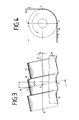
- FIGS. 3 and 4 The principle of operation of the roller according to FIG. 2 is shown in more detail schematically in FIGS. 3 and 4.
- the outer bushings 19, 19 ', 19 “are shown much more inclined than the longitudinal axis B by the angle ⁇ ' for better clarity than in the drawing according to FIG. 2.
- the film web 26 touches the outer bush 19 and at location a, for example leaves this again at location b with a wrap of a quarter of the outer bushing 19.
Landscapes
- Engineering & Computer Science (AREA)
- Chemical & Material Sciences (AREA)
- General Engineering & Computer Science (AREA)
- Mechanical Engineering (AREA)
- Chemical Kinetics & Catalysis (AREA)
- Materials Engineering (AREA)
- Metallurgy (AREA)
- Organic Chemistry (AREA)
- Rolls And Other Rotary Bodies (AREA)
- Processing And Handling Of Plastics And Other Materials For Molding In General (AREA)
- Shaping By String And By Release Of Stress In Plastics And The Like (AREA)
- Physical Vapour Deposition (AREA)
Abstract
Description
- Die Erfindung betrifft eine Walze zum Führen und Strecken von Bändern und/oder Folienbahnen für Wickeleinrichtungen, vorzugsweise für Vorrichtungen zum kontinuierlichen Bedampfen von Kunststoffbändern und -bahnen im Vakuum.
- Bekannt ist eine Streck- und Stauchwalze für Bogen oder Bahnen aus biegsamem Werkstoff (DE-PS 892 286), die zwischen den Endabschnitten eine gebogene Strecke aufweist und die - mit der gebogenen Achse der Walze in beliebigen Ebenen einstellbar - festgeklemmt werden können. Derartige Streck- und Stauchwalzen sind mit einem elastischen Schlauch aus textilem Werkstoff versehen, der über die einzelnen Walzenabschnitte gezogen ist und so für einen kontinuierlichen Lauf der Walzenabschnitte sorgt. Diese bekannte Walze hat unter anderem den Nachteil, daß sie sich erfahrungsgemäß stark elektrostatisch auflädt, was bei einer Wickeleinrichtung für eine Sputtervorrichtung nicht akzeptabel ist.
- Der vorliegenden Erfindung liegt nun die Aufgabe zugrunde, eine Walze des in Frage stehenden Typs zu schaffen, die preiswert in der Herstellung ist, deren Gleichlauf von besonderer Präzision ist, die geringe Geräusche erzeugt, die hohe Drehzahlen bei Vermeidung eines besonderen Schmiersystems ermöglicht und die auch unter den Bedingungen eines Hochvakuums ihre Eigenschaften behält, also beispielsweise keine Teile enthält, die aus Werkstoffen bestehen, die zum Ausgasen und damit zum Brüchigwerden neigen.
- Diese Aufgabe wird gemäß der Erfindung durch eine Vielzahl von auf der Walzenachse hintereinanderliegend angeordneten, nach Art von Axial-Zylinderrollenlagern auf der Achse über Wälzkörper drehbar geführte Außenbuchsen gleicher Konfiguration gelöst, wobei die Außenbuchsen im Abstand zueinander gehalten sind und das Band oder die Folienbahn die Außenbuchsen zunächst teilweise umschlingt und dabei mit Vorspannung an Partien der Zylindermantelflächen der Außenbuchsen anliegt.
- Vorzugsweise rollen dabei die jeder Außenbuchse zugeordneten Wälzkörper unmittelbar auf einer gebogenen Achse ab, wobei sie gegen axiales Verschieben gegenüber der jeweiligen Außenbuchse durch in diese eingepreßte Ringe gesichert sind, wobei jeder Ring - zusammen mit einer sich radial nach innen zu erstreckenden Stufe - in der Innenbohrung jeder Außenbuchse einen Käfig für den Wälzkörpersatz bildet.
- Zweckmäßigerweise sind die einer Außenbuchse zugeordneten Wälzkörper gegenüber den Wälzkörpern der benachbarten Außenbuchse durch auf die Achse aufgeschobene Ringe im Abstand zueinander gehalten, wobei der an den Wälzkörpern zweier benachbarter Außenbuchsen anliegende Ring in seiner Breite so bemessen ist, daß die einander zugekehrten Stirnflächen dieser Außenbuchsen stets einen Mindestabstand voneinander aufweisen.
- Bei einer bevorzugten Ausführungsform der Erfindung rollen die jeweils einer Außenbuchse zugeordneten Wälzkörper auf Innenbuchsen ab, die hintereinanderliegend auf die gerade Achse aufgeschoben sind, wobei mindestens eine der Innenbuchsen eine die Lauffläche für die Wälzkörper bildende zylindrische Außenfläche aufweist, deren Rotationsachse in einem spitzen Winkel zur Rotationsachse der zylindrischen Innenbohrung der Innenbuchse verläuft.
- Mit Vorteil weist die Innenbuchse eine sich radial nach außen zu erstreckende Stufe oder Schulter auf, an der die zugeordneten Wälzkörper anliegen, die im übrigen durch zwei in die Außenbuchse eingepreßte Ringe an einer axialen Verschiebung - relativ zur Außenbuchse - gesichert sind.
- Um sicherzustellen, daß die Innenbuchsen mit ihren geneigten Außenmantelflächen sich nicht relativ gegeneinander verdrehen, sind diese an ihren einander zugekehrten Stirnflächen mit Verzahnungen, Verzapfungen oder ineinandergreifenden Vorsprüngen versehen.
- Die Erfindung läßt die verschiedensten Ausführungsmöglichkeiten zu; zwei davon sind in den anhängenden Zeichnungen prinzipiell dargestellt, und zwar zeigen:
- Fig. 1 den Teillängsschnitt durch eine Walze mit einer gebogenen Achse,
- Fig. 2 den Teillängssschnitt durch eine Walze mit einer geraden Achse und mit auf dieser angeordneten Innenbuchsen und den auf diesen Innenbuchsen abrollenden Wälzkörpern und
- Fig. 3 & 4 rein schematische Darstellungen der Funktionen der Walze nach Figur 2.
- Die Walze zum Führen bzw. Strecken von Bandwickeln gemäß Figur 1 besteht im wesentlichen aus einer gebogenen Walzenachse 3, deren beide Enden im (nicht näher dargestellten) Maschinengestell gehalten sind und einer Vielzahl von auf der Walzenachse 3 hintereinanderliegend angeordneten zylindrischen Abstandsbuchsen 4, 4', ..., die jeweils durch Gruppen oder Sätze 5, 5', 5", ... von Wälzkörpern 6, 7, 8 auf Abstand gehalten sind, wobei die einzelnen Wälzkörpersätze 5, 5', 5", ... jeweils von Außenbuchsen 9, 9', 9" umschlossen sind, so daß sich eine Vielzahl von nebeneinanderliegend angeordneten Axial-Zylinderrollenlager ergeben, deren sich jeweils quer zur Rotationsachse A durch den Wälzkörpersatz erstreckenden mittigen Ebenen e, e', e", ... jeweils unter einem spitzen Winkel a, a', a", ... geneigt zueinander verlaufen. In die Außenbuchsen 9, 9', 9", ... sind jeweils Ringe oder Buchsen 10, 10', 10",... eingepreßt, die dafür Sorge tragen, daß die von den Außenbuchsen 9, 9', 9", ... umschlossenen Wälzkörper 6, 6', ... in ihrer Bewegung in Richtung der Längsachse A begrenzt sind. Die Außenbuchsen 9, 9', 9", ... weisen dazu an ihren Innenflächen außerdem jeweils einen Flansch oder eine Schulter 11, 11', 11", ... auf, an denen jeweils die entsprechenden Wälzkörper 6, 7, 8 der Wälzkörpersätze 5, 5', ... anliegen.
- Bei der Walzenausführung gemäß Figur 2 ist die in das Maschinengestell eingespannte Achse 12 gerade ausgebildet und im Gegensatz zu derjenigen nach Figur 1 mit einer Vielzahl von hintereinanderliegend angeordneten Innenbuchsen 13, 13', 13", ... versehen, auf denen jeweils die Wälzkörper 14, 15, 16, 17 der Wälzkörpersätze 18, 18', ... abrollen. Alle Wälzkörpersätze 18, 18', 18", ... sind von hohlzylindirschen Außenbuchsen 19, 19', 19", ... umschlossen, wobei die Wälzkörper 14, 15, 16, 17 gegen ein axiales Verschieben mit Hilfe von in die Außenbuchsen 19, 19', 19", ... eingesetzte hohlzylindrische Buchsen 20, 20' bzw. 21, 21' bzw. 22, 22', ...) gesichert sind. Die Innenbuchsen 13, 13', 13", ... weisen jeweils eine zylindrische Innenbohrung (25, 25"', ...) und eine jeweils zu dieser Innenbohrung in einem Winkel β schräg verlaufende zylindrische Außenmantelfläche 24, 24', 4'" auf. Bei der Ausführungsform gemäß Figur 2 ist jedoch eine der Innenbuchsen 13" mit einer zylindrischen Mantelfläche 24" versehen, deren Rotationsachse mit derjenigen der Innenbohrung 25" zusammenfällt; außerdem ist die schräge zylindrische Mantelfläche 24"' der Innenbuchse 13"' auf der rechten Seite der Innenbuchse 13"' vorgesehen, während die schrägen Mantelflächen 24, 24' der beiden linken Innenbuchsen 13, 13' auf der linken Seite der Walze angeordnet sind, so daß die über die Außenbuchsen 19, 19', 19", ... abrollende Folienbahn 26 faltenfrei bzw. glatt gezogen bzw. gestreckt wird.
- Das Funktionsprinzip der Walze gemäß Figur 2 ist in den Figuren 3 und 4 rein schematisch näher gezeigt. In diesem Falle sind die Außenbuchsen 19, 19', 19" der besseren Übersichtlichkeit wegen gegenüber der Längsachse B um die Winkel β' weitaus stärker geneigt dargestellt als in der Zeichnung gemäß Figur 2. Die Folienbahn 26 berührt beispielsweise am Orte a die Außenbuchse 19 und verläßt diese wieder am Orte b bei einer Umschlingung eines Viertels der Außenbuchse 19.
- Bei einer Umschlingung einer Hälfte des Umfangs der Außenbuchse 19 hebt die Folienbahn 26 im Orte c von der Außenbuchse 19 ab. Infolge der Schrägstellung der Rotationsachse R zur Längsachse B um den Winkel β' wandert dabei der angenommene Berührungsort a zwischen Folienbahn 26 und der Außenbuchse 19, um die Strecke d nach links bis zum Ort b, wenn die Folienbahn 26 die Außenbuchse 19 zu einem Viertel umschlingt (= optimaler Umschlingungswinkel), und um die Strecke f, wenn als Abhebeort c (= maximaler Umschlingungswinkel) gewählt wurde.
- Um zu verhindern, daß sich die einzelnen, auf die Achse 12 aufgeschobenen Innenbuchsen 13, 13', ... gegeneinander verdrehen, sind ihre Stirnflächen jeweils mit Verzapfungen oder Verzahnungen 28, 28', ... versehen.
-
- 3 gebogene Walzenachse
- 4, 4', 4", ...
- Abstandsbuchse
- 5, 5', 5", ...
- Wälzkörpersatz
- 6 Wälzkörper
- 7 Wälzkörper
- 8 Wälzkörper
- 9, 9', 9", ...
- Außenbuchse
- 10, 10', 10", ...
- Buchse
- 11, 11', 11",
- Schulter
- 12 Achse
- 13, 13', 13", ...
- Innenbuchse
- 14 Wälzkörper
- 15 Wälzkörper
- 16 Wälzkörper
- 17 Wälzkörper
- 18, 18', 18", ...
- Wälzkörpersatz
- 19, 19', 19", ...
- Außenbuchse
- 20, 20'
- Buchse
- 21, 21'
- Buchse
- 22, 22'
- Buchse
- 23, 23'
- Buchse
- 24, 24', 24", ...
- zylindrische Außenmantelfläche
- 25, 25', 25", ...
- Innenbohrung
- 26 Folienbahn
- 27, 27', ...
- Schulter
- 28, 28', ...
- Zapfen, Verzahnung
- a, a', α",...
- Neigungswinkel zwischen zwei Axial-Zylinderrollenlagern
- e, e', e",
- Ebene quer durch ein Zylinderrollenlager A
- Längsachse
- B Längsachse
- R Rotationsachse
- a Berührungsort Folienbahn 26 -
- Außenbuchse 19
- b Abhebeort Folienbahn 26 -
- Außenbuchse 19
- c Abhebeort Folienbahn 26 -
- Außenbuchse 19
- d Seitenversatz (Breitführstrecke)
- f Seitenversatz (Breitführstrecke)
- ß Neigungswinkel zwischen der zylindrischen Außenmantelfläche 19 und der Längsachse B
- g Mindestabstand
- h Mindestabstand
Claims (7)
Applications Claiming Priority (2)
| Application Number | Priority Date | Filing Date | Title |
|---|---|---|---|
| DE4025232A DE4025232A1 (de) | 1990-08-09 | 1990-08-09 | Walze zum fuehren und strecken von baendern und/oder folienbahnen |
| DE4025232 | 1990-08-09 |
Publications (2)
| Publication Number | Publication Date |
|---|---|
| EP0470332A1 true EP0470332A1 (de) | 1992-02-12 |
| EP0470332B1 EP0470332B1 (de) | 1995-09-20 |
Family
ID=6411919
Family Applications (1)
| Application Number | Title | Priority Date | Filing Date |
|---|---|---|---|
| EP91106480A Expired - Lifetime EP0470332B1 (de) | 1990-08-09 | 1991-04-23 | Walze zum Führen und Strecken von Bändern und/oder Folienbahnen |
Country Status (3)
| Country | Link |
|---|---|
| EP (1) | EP0470332B1 (de) |
| JP (1) | JP3626759B2 (de) |
| DE (2) | DE4025232A1 (de) |
Cited By (3)
| Publication number | Priority date | Publication date | Assignee | Title |
|---|---|---|---|---|
| DE19901089A1 (de) * | 1999-01-14 | 2000-07-20 | Leybold Systems Gmbh | Streckvorrichtung für eine Materialbahn |
| EP1580446A1 (de) * | 2004-03-26 | 2005-09-28 | Applied Films GmbH & Co. KG | Verfahren zum Betrieb von Vakuumanlagen mit Drückänderungen |
| EP2098470A1 (de) | 2008-03-03 | 2009-09-09 | Applied Materials, Inc. | Wickelvorrichtung zum Wickeln eines bandförmigen Materials |
Families Citing this family (4)
| Publication number | Priority date | Publication date | Assignee | Title |
|---|---|---|---|---|
| DE4126535C2 (de) * | 1991-08-10 | 2001-10-18 | Applied Films Gmbh & Co Kg | Walze zum Führen und Strecken von Bändern und/oder Folienbahnen |
| IT1286831B1 (it) | 1996-09-11 | 1998-07-17 | Galileo Vacuum Tec Spa | Rullo per allargare e distendere un materiale nastriforme |
| JP4694066B2 (ja) * | 2001-09-28 | 2011-06-01 | 株式会社日立プラントテクノロジー | シート状物の同時二軸延伸機 |
| DE102013017281B4 (de) | 2013-06-21 | 2015-09-24 | Texmag Gmbh Vertriebsgesellschaft | Walze zum Führen und/oder Breitstrecken einer laufenden Warenbahn |
Citations (8)
| Publication number | Priority date | Publication date | Assignee | Title |
|---|---|---|---|---|
| GB875737A (en) * | 1959-01-16 | 1961-08-23 | Btr Industries Ltd | Improvements in or relating to rollers for pickling baths |
| DE2201844A1 (de) * | 1972-01-15 | 1973-08-09 | Ahlstroem Dev Gmbh | Walze zur ausuebung eines gleichmaessigen drucks |
| FR2210240A5 (en) * | 1972-12-13 | 1974-07-05 | Mount Hope Machinery Ltd | Arcuate-shaped roller - for stretching materials or pressing them together |
| FR2416377A1 (fr) * | 1978-02-02 | 1979-08-31 | Baker Perkins Holdings Ltd | Rouleau de transport de liquide, notamment pour presse d'imprimerie |
| DE3338965A1 (de) * | 1983-10-27 | 1985-05-09 | Gummiwerke Becker AG, 7920 Heidenheim | Vorrichtung zum dehnen und/oder streichen einer bewegten bahn |
| DE8610958U1 (de) * | 1986-04-22 | 1986-07-03 | H. Wittler GmbH & Co KG, 4800 Bielefeld | Breitstreckwalze |
| US4674667A (en) * | 1985-12-18 | 1987-06-23 | Isamu Tsuchida | Apparatus for correcting the lateral displacement of a moving metallic sheet |
| DE8907282U1 (de) * | 1989-06-14 | 1989-11-16 | H. Wittler GmbH & Co KG, 33758 Schloß Holte-Stukenbrock | Breitstreckwalze, insbesondere für die Behandlung von Textil-, Papier- oder Kunststoffbahnen |
Family Cites Families (5)
| Publication number | Priority date | Publication date | Assignee | Title |
|---|---|---|---|---|
| DE7421247U (de) * | 1974-10-17 | Wittler H & Co | Breitstreckwalze für biegsame Papier-, Textil- oder Kunststoffbahnen | |
| CH599022A5 (de) * | 1976-09-10 | 1978-05-12 | Fred H Freuler | |
| DE3324160A1 (de) * | 1983-07-05 | 1985-01-24 | H. Wittler GmbH & Co KG, 4800 Bielefeld | Breitstreckwalze |
| DE3613494A1 (de) * | 1986-04-22 | 1987-11-05 | Wittler H Gmbh & Co Kg | Breitstreckwalze |
| DE3733448A1 (de) * | 1987-09-09 | 1989-03-23 | Becker Gummiwerke | Breitstreckwalze |
-
1990
- 1990-08-09 DE DE4025232A patent/DE4025232A1/de not_active Ceased
-
1991
- 1991-04-23 DE DE59106513T patent/DE59106513D1/de not_active Expired - Fee Related
- 1991-04-23 EP EP91106480A patent/EP0470332B1/de not_active Expired - Lifetime
- 1991-08-05 JP JP19528891A patent/JP3626759B2/ja not_active Expired - Fee Related
Patent Citations (8)
| Publication number | Priority date | Publication date | Assignee | Title |
|---|---|---|---|---|
| GB875737A (en) * | 1959-01-16 | 1961-08-23 | Btr Industries Ltd | Improvements in or relating to rollers for pickling baths |
| DE2201844A1 (de) * | 1972-01-15 | 1973-08-09 | Ahlstroem Dev Gmbh | Walze zur ausuebung eines gleichmaessigen drucks |
| FR2210240A5 (en) * | 1972-12-13 | 1974-07-05 | Mount Hope Machinery Ltd | Arcuate-shaped roller - for stretching materials or pressing them together |
| FR2416377A1 (fr) * | 1978-02-02 | 1979-08-31 | Baker Perkins Holdings Ltd | Rouleau de transport de liquide, notamment pour presse d'imprimerie |
| DE3338965A1 (de) * | 1983-10-27 | 1985-05-09 | Gummiwerke Becker AG, 7920 Heidenheim | Vorrichtung zum dehnen und/oder streichen einer bewegten bahn |
| US4674667A (en) * | 1985-12-18 | 1987-06-23 | Isamu Tsuchida | Apparatus for correcting the lateral displacement of a moving metallic sheet |
| DE8610958U1 (de) * | 1986-04-22 | 1986-07-03 | H. Wittler GmbH & Co KG, 4800 Bielefeld | Breitstreckwalze |
| DE8907282U1 (de) * | 1989-06-14 | 1989-11-16 | H. Wittler GmbH & Co KG, 33758 Schloß Holte-Stukenbrock | Breitstreckwalze, insbesondere für die Behandlung von Textil-, Papier- oder Kunststoffbahnen |
Cited By (4)
| Publication number | Priority date | Publication date | Assignee | Title |
|---|---|---|---|---|
| DE19901089A1 (de) * | 1999-01-14 | 2000-07-20 | Leybold Systems Gmbh | Streckvorrichtung für eine Materialbahn |
| EP1580446A1 (de) * | 2004-03-26 | 2005-09-28 | Applied Films GmbH & Co. KG | Verfahren zum Betrieb von Vakuumanlagen mit Drückänderungen |
| US7153372B2 (en) | 2004-03-26 | 2006-12-26 | Applied Materials Gmbh & Co. Kg. | Method for removing particles from elements installed in a vacuum chamber |
| EP2098470A1 (de) | 2008-03-03 | 2009-09-09 | Applied Materials, Inc. | Wickelvorrichtung zum Wickeln eines bandförmigen Materials |
Also Published As
| Publication number | Publication date |
|---|---|
| EP0470332B1 (de) | 1995-09-20 |
| JPH04232268A (ja) | 1992-08-20 |
| JP3626759B2 (ja) | 2005-03-09 |
| DE4025232A1 (de) | 1992-02-13 |
| DE59106513D1 (de) | 1995-10-26 |
Similar Documents
| Publication | Publication Date | Title |
|---|---|---|
| DE19833436B4 (de) | Nabeneinheit-Komplettlager und Verfahren zur Herstellung desselben | |
| DE4442404C2 (de) | Verdrehsicherung für einen Kunststoffkäfig eines Freilaufs | |
| DE3841629C2 (de) | Rollenlagerung | |
| DE3852479T2 (de) | Dichtungs- und Staubschutzeinheit für einen Kreuzgelenkzapfen. | |
| CH454180A (de) | Vorrichtung zum Pressen von in einem kontinuierlichen Strom anfallenden, biegsamen Flächengebilden | |
| DE3501635A1 (de) | Presswalze | |
| DD200850A5 (de) | Uebertragungsvorrichtung fuer staebchenfoermige artikel | |
| DE19827859A1 (de) | Mehrreihiges Radiallager | |
| DE2246975A1 (de) | Antriebs- und umlenkrollen fuer bandfoerderer und mit diesen rollen ausgestattete bandfoerderer | |
| DE202017001904U1 (de) | Spreizwalze zum seitlichen Ausbreiten einer flächigen Materialbahn sowie Vorrichtung zum Handhaben von flächigen Materialbahnen | |
| EP0527291A1 (de) | Walze zum Führen und Strecken von Bändern und/oder Folienbahnen | |
| EP0470332A1 (de) | Walze zum Führen und Strecken von Bändern und/oder Folienbahnen | |
| DE3331052A1 (de) | Waren-abzugswalze an flachstrickmaschinen | |
| EP1033083A1 (de) | Vorrichtung zum Verschieben von stabförmigen Artikeln der tabakverarbeitenden Industrie in Richtung ihrer Längsachsen | |
| DE4431648C1 (de) | Andrückwalze für das Andrücken einer laufenden Warenbahn | |
| DE2612375C2 (de) | Spannkopf für die die Kernrohre von Wickeln aus Papier, Kunststoffolien oder dergleichen | |
| EP1123247B1 (de) | Kontaktwalzensystem einer wickelmaschine | |
| DE19601044A1 (de) | Zylinderrollenlager | |
| DE4040844A1 (de) | Trag- oder foerderrolle | |
| DE4343096C1 (de) | Tripodegelenk mit Rollensicherung | |
| DD202388A5 (de) | Trennungseinrichtung fuer eine filterbefestigungsmaschine einer zigarettenherstellungsmaschine | |
| WO1993001116A1 (de) | Führungskopf für schwere wickelrollen | |
| DD157880A5 (de) | Vorrichtung zum aufnehmen einer schlauchfolie | |
| DE2836399C2 (de) | Bolzenkäfig für selbsteinstellende Rollenlager | |
| EP2298678B1 (de) | Wickelvorrichtung |
Legal Events
| Date | Code | Title | Description |
|---|---|---|---|
| PUAI | Public reference made under article 153(3) epc to a published international application that has entered the european phase |
Free format text: ORIGINAL CODE: 0009012 |
|
| AK | Designated contracting states |
Kind code of ref document: A1 Designated state(s): CH DE FR GB IT LI SE |
|
| 17P | Request for examination filed |
Effective date: 19920316 |
|
| 17Q | First examination report despatched |
Effective date: 19931220 |
|
| GRAA | (expected) grant |
Free format text: ORIGINAL CODE: 0009210 |
|
| ITF | It: translation for a ep patent filed | ||
| AK | Designated contracting states |
Kind code of ref document: B1 Designated state(s): CH DE FR GB IT LI SE |
|
| GBT | Gb: translation of ep patent filed (gb section 77(6)(a)/1977) |
Effective date: 19950914 |
|
| REF | Corresponds to: |
Ref document number: 59106513 Country of ref document: DE Date of ref document: 19951026 |
|
| ET | Fr: translation filed | ||
| PLBE | No opposition filed within time limit |
Free format text: ORIGINAL CODE: 0009261 |
|
| STAA | Information on the status of an ep patent application or granted ep patent |
Free format text: STATUS: NO OPPOSITION FILED WITHIN TIME LIMIT |
|
| 26N | No opposition filed | ||
| REG | Reference to a national code |
Ref country code: GB Ref legal event code: IF02 |
|
| REG | Reference to a national code |
Ref country code: FR Ref legal event code: CD Ref country code: FR Ref legal event code: TP |
|
| REG | Reference to a national code |
Ref country code: CH Ref legal event code: NV Representative=s name: PATENTANWAELTE FELDMANN & PARTNER AG Ref country code: CH Ref legal event code: PUE Owner name: APPLIED FILMS GMBH & CO. KG Free format text: LEYBOLD AKTIENGESELLSCHAFT#WILHELM-ROHN-STRASSE 25#D-63450 HANAU (DE) -TRANSFER TO- APPLIED FILMS GMBH & CO. KG#SIEMENSSTRASSE 100#63755 ALZENAU (DE) |
|
| REG | Reference to a national code |
Ref country code: GB Ref legal event code: 732E |
|
| REG | Reference to a national code |
Ref country code: CH Ref legal event code: PFA Owner name: APPLIED MATERIALS GMBH & CO. KG Free format text: APPLIED MATERIALS GMBH & CO. KG#SIEMENSSTRASSE 100#63755 ALZENAU (DE) -TRANSFER TO- APPLIED MATERIALS GMBH & CO. KG#SIEMENSSTRASSE 100#63755 ALZENAU (DE) Ref country code: CH Ref legal event code: PFA Owner name: APPLIED MATERIALS GMBH & CO. KG Free format text: APPLIED FILMS GMBH & CO. KG#SIEMENSSTRASSE 100#63755 ALZENAU (DE) -TRANSFER TO- APPLIED MATERIALS GMBH & CO. KG#SIEMENSSTRASSE 100#63755 ALZENAU (DE) |
|
| PGFP | Annual fee paid to national office [announced via postgrant information from national office to epo] |
Ref country code: CH Payment date: 20080325 Year of fee payment: 18 |
|
| PGFP | Annual fee paid to national office [announced via postgrant information from national office to epo] |
Ref country code: GB Payment date: 20080320 Year of fee payment: 18 Ref country code: SE Payment date: 20080319 Year of fee payment: 18 |
|
| PGFP | Annual fee paid to national office [announced via postgrant information from national office to epo] |
Ref country code: DE Payment date: 20080320 Year of fee payment: 18 Ref country code: FR Payment date: 20080313 Year of fee payment: 18 |
|
| REG | Reference to a national code |
Ref country code: FR Ref legal event code: CD |
|
| PGFP | Annual fee paid to national office [announced via postgrant information from national office to epo] |
Ref country code: IT Payment date: 20080329 Year of fee payment: 18 |
|
| REG | Reference to a national code |
Ref country code: CH Ref legal event code: PL |
|
| EUG | Se: european patent has lapsed | ||
| GBPC | Gb: european patent ceased through non-payment of renewal fee |
Effective date: 20090423 |
|
| REG | Reference to a national code |
Ref country code: FR Ref legal event code: ST Effective date: 20091231 |
|
| PG25 | Lapsed in a contracting state [announced via postgrant information from national office to epo] |
Ref country code: DE Free format text: LAPSE BECAUSE OF NON-PAYMENT OF DUE FEES Effective date: 20091103 Ref country code: LI Free format text: LAPSE BECAUSE OF NON-PAYMENT OF DUE FEES Effective date: 20090430 Ref country code: CH Free format text: LAPSE BECAUSE OF NON-PAYMENT OF DUE FEES Effective date: 20090430 |
|
| PG25 | Lapsed in a contracting state [announced via postgrant information from national office to epo] |
Ref country code: GB Free format text: LAPSE BECAUSE OF NON-PAYMENT OF DUE FEES Effective date: 20090423 Ref country code: FR Free format text: LAPSE BECAUSE OF NON-PAYMENT OF DUE FEES Effective date: 20091222 |
|
| PG25 | Lapsed in a contracting state [announced via postgrant information from national office to epo] |
Ref country code: IT Free format text: LAPSE BECAUSE OF NON-PAYMENT OF DUE FEES Effective date: 20090423 |
|
| PG25 | Lapsed in a contracting state [announced via postgrant information from national office to epo] |
Ref country code: SE Free format text: LAPSE BECAUSE OF NON-PAYMENT OF DUE FEES Effective date: 20090424 |