EP0468064A1 - Stützelement für einstellbare Jalousielamellen von Läden mit vereinfachtem Zusammenbau - Google Patents
Stützelement für einstellbare Jalousielamellen von Läden mit vereinfachtem Zusammenbau Download PDFInfo
- Publication number
- EP0468064A1 EP0468064A1 EP90114037A EP90114037A EP0468064A1 EP 0468064 A1 EP0468064 A1 EP 0468064A1 EP 90114037 A EP90114037 A EP 90114037A EP 90114037 A EP90114037 A EP 90114037A EP 0468064 A1 EP0468064 A1 EP 0468064A1
- Authority
- EP
- European Patent Office
- Prior art keywords
- supporting element
- louver
- louver board
- wall
- board
- Prior art date
- Legal status (The legal status is an assumption and is not a legal conclusion. Google has not performed a legal analysis and makes no representation as to the accuracy of the status listed.)
- Granted
Links
Images

Classifications
-
- E—FIXED CONSTRUCTIONS
- E06—DOORS, WINDOWS, SHUTTERS, OR ROLLER BLINDS IN GENERAL; LADDERS
- E06B—FIXED OR MOVABLE CLOSURES FOR OPENINGS IN BUILDINGS, VEHICLES, FENCES OR LIKE ENCLOSURES IN GENERAL, e.g. DOORS, WINDOWS, BLINDS, GATES
- E06B7/00—Special arrangements or measures in connection with doors or windows
- E06B7/02—Special arrangements or measures in connection with doors or windows for providing ventilation, e.g. through double windows; Arrangement of ventilation roses
- E06B7/08—Louvre doors, windows or grilles
- E06B7/084—Louvre doors, windows or grilles with rotatable lamellae
Definitions
- the present invention relates to a supporting element for orientatable louver boards for shutters with simplified assembly.
- the installation of a shutter with orientatable louver boards usually initially entails the insertion of the louver board supporting elements into the ends of said louver boards along a direction which is substantially parallel to the axis of the louver boards and subsequently the association of the supporting elements, with the respective assembled louver boards, with the uprights of the frame of the shutter.
- This assembly system has considerable disadvantages, the first of which is the fact that if the dimension of the frame of the shutter do not perfectly match the dimensions of the seat in which said shutter is to be mounted it is necessary to dismantle all the louver boards from their supports in order to replace them with longer louver boards or possibly shorten them to the required size.
- the aim of the present invention is to eliminate the above described disadvantages by providing a supporting element for orientatable louver boards for shutters with simplified assembly which can be coupled to the louver boards when the frame of the shutter is already assembled and can be uncoupled from said louver boards along a direction which differs from the assembly direction.
- an important object of the invention is to provide a supporting element for orientatable louver boards for shutters with simplified assembly which effectively retains the louver boards once they are associated therewith.
- Another object of the present invention is to provide an orientatable louver board for shutters in which, when the louver boards are in closed position, the regions of contact with the other louver boards define a perfect barrier to the passage of light.
- Not least object is to provide a supporting element for orientatable louver boards which has no play once it is assembled to the louver boards.
- a supporting element for orientatable louver boards for shutters with simplified assembly which comprise a hollow body which has, on its two longer sides, variously shaped seats for coupling to other orientatable louver boards of the shutter, characterized in that it comprises guiding means and retention means for associating said louver board with said supporting element along a direction which is substantially orthogonal to the axis of said louver board, said retention means being adapted to release said louver board from said supporting element along two mutually orthogonal directions, one of which is substantially parallel to said axis of said louver board.
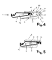
- each orientatable louver board for shutters with simplified assembly comprises a hollow body 2 which has, on its two longer sides, which are arranged to the right and to the left of the hollow body in the drawing, variously shaped seats, generally indicated by the reference numerals 3 and 4, adapted to couple to the other orientatable louver boards of the shutter, as illustrated in figure 2.
- a supporting element 5 according to the invention is mounted on each end of the louver boards and is rotatably coupled to the lateral uprights of the shutter, which are not illustrated in the drawings.
- Each of the supporting elements 5 has guiding means, generally indicated by the reference numeral 6, and retention means, indicated by 7, to allow the valid retention of the louver board to the supporting element along a direction which is substantially orthogonal to the axis of said louver board.
- the guiding means 6 comprise a first wall 8 and a second wall 9 which define between them a region 10 for the accommodation of the louver board; the configuration and width of said accommodation region are substantially equal to those of the cross section of the hollow body of the louver board.
- the second wall 9 is furthermore inclined with respect to the first wall 5 by the same angle by which the corresponding surface 11 of the louver board is inclined.
- the retention means 7 comprise at least one raised portion and more in particular two raised portions 12 and 13 which extend perpendicular from the accommodation region 10.
- Each of said raised portions 12 and 13 has an upper wall 29 which is inclined so as to facilitate the insertion of the louver board in the supporting element and a wall 30 which is orthogonal to the accommodation region so as to provide a final locking to the supporting element by virtue of its engagement with the inner surface thereof.
- the raised portion 12 engages within the hollow body 2, whereas the raised portion 13 engages within the seat 4 or, in a constructive variation, the raised portion 12 engages within the seat 3.
- the second wall 9 furthermore has, on the opposite side with respect to the two raised portions 12 and 13, a curved end portion 14 the function whereof is to co-operate with the raised portions 12 and 13 to retain the louver board to the supporting element.
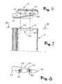
- each seat has recessed parts 18 on one which are located at protruding parts 17 of the other, so as to define a labyrinth-like path which has at least two barrier regions and more precisely three barrier regions against the passage of light when the louver boards are in closed position.
- a recess 15 for accommodating a sealing gasket 16 is furthermore advantageously provided in the seat 3; said gasket is defined by a first rod 19 from which a second rod 20 extends vertically; two wings 21 divergently extend from said second rod.
- the wings 21 are simultaneously in contact with the shoulders 22 of two contiguous louver boards so as to provide a perfect seal, preventing the passage of dust or water as well as light.
- the retention means comprise at least one coupling element 40 which has, on one side, a raised portion 41 adapted to be inserted within each louver board 2 and, on the opposite side with respect to the raised portion 41, at least one pin, two pins 42 in the illustrated example, suitable for engaging snap-together in respective holes 43 provided in the supporting element when the louver board is associated therewith.
- the pins 42 are conveniently associated with respective tabs 44 which are elastically yielding since they are coupled to the accommodation region 10 of the supporting element only with one of their sides.
- the coupling element can also be provided without the two end portions 45 and 46 and therefore its exact placement on the supporting element is obtained by providing thereon two steps 47 and 48 which abut on the end portions 45 and 46 of the coupling element which are indicated in broken lines in figure 7.
- louver board With the respective supporting element according to the invention is evident from which has been described and illustrated; in particular, with reference to figures 4 and 5, it can be seen that by moving the louver board along a direction which is substantially perpendicular to its longitudinal axis, also by virtue of the presence of the second wall 9, said louver board is guided until it is proximate to the raised portions 12 and 13 or to the holes 43 if the coupling element 40 is associated with the louver board.
- the raised portions 12 and 13 By subsequently exerting a slight pressure, the raised portions 12 and 13, by virtue of the presence of an inclined wall on their face, respectively insert in the seat 4 and within the hollow body 2 or the seat 3 of the louver board, locking said louver board to the supporting element 5.
- the pins 42 insert in the respective holes 43 if the coupling element 40 is associated with the louver board.
- the curved end portion 14 of the second wall 6 furthermore co-operates to retain in place the louver board 1 within its accommodation region in the supporting element.
- the orientatable louver board for shutters with simplified assembly according to the invention is particularly advantageous in that it allows the casement installer for example to couple a specimen louver board to the respective supporting element after mounting the shutter's frame, to check if the length of the louver board is exactly the preset one and thus confidently mount all the remaining louver boards on the respective supporting elements.
- the length of the louver board is not the preset one, it is possible to already preset the other louver boards with the right measurements without the disadvantage of having rejects.
- the materials employed, as well as the dimensions, may be any according to the requirements and the state of the art.
Landscapes
- Engineering & Computer Science (AREA)
- Civil Engineering (AREA)
- Structural Engineering (AREA)
- Specific Sealing Or Ventilating Devices For Doors And Windows (AREA)
- Blinds (AREA)
Priority Applications (5)
| Application Number | Priority Date | Filing Date | Title |
|---|---|---|---|
| DE69031273T DE69031273D1 (de) | 1990-07-23 | 1990-07-23 | Stützelement für einstellbare Jalousielamellen von Läden mit vereinfachtem Zusammenbau |
| AT90114037T ATE156890T1 (de) | 1990-07-23 | 1990-07-23 | Stützelement für einstellbare jalousielamellen von läden mit vereinfachtem zusammenbau |
| ES90114037T ES2107415T3 (es) | 1990-07-23 | 1990-07-23 | Un elemento de soporte para tablas de lamas. |
| EP90114037A EP0468064B1 (de) | 1990-07-23 | 1990-07-23 | Stützelement für einstellbare Jalousielamellen von Läden mit vereinfachtem Zusammenbau |
| GR970402990T GR3025348T3 (en) | 1990-07-23 | 1997-11-11 | Supporting element for orientable louver boards for shutters with simplified assembly |
Applications Claiming Priority (1)
| Application Number | Priority Date | Filing Date | Title |
|---|---|---|---|
| EP90114037A EP0468064B1 (de) | 1990-07-23 | 1990-07-23 | Stützelement für einstellbare Jalousielamellen von Läden mit vereinfachtem Zusammenbau |
Publications (2)
| Publication Number | Publication Date |
|---|---|
| EP0468064A1 true EP0468064A1 (de) | 1992-01-29 |
| EP0468064B1 EP0468064B1 (de) | 1997-08-13 |
Family
ID=8204244
Family Applications (1)
| Application Number | Title | Priority Date | Filing Date |
|---|---|---|---|
| EP90114037A Expired - Lifetime EP0468064B1 (de) | 1990-07-23 | 1990-07-23 | Stützelement für einstellbare Jalousielamellen von Läden mit vereinfachtem Zusammenbau |
Country Status (5)
| Country | Link |
|---|---|
| EP (1) | EP0468064B1 (de) |
| AT (1) | ATE156890T1 (de) |
| DE (1) | DE69031273D1 (de) |
| ES (1) | ES2107415T3 (de) |
| GR (1) | GR3025348T3 (de) |
Cited By (2)
| Publication number | Priority date | Publication date | Assignee | Title |
|---|---|---|---|---|
| EP1566517A2 (de) * | 2004-02-23 | 2005-08-24 | TEKNALSYSTEMS Srl | Verstellbare Lamelle ohne Dichtelement eines dicht schließenden Fensterladens und Halteelement dafür |
| EP2431547A1 (de) * | 2010-09-21 | 2012-03-21 | Frigerio Tende Da Sole S.r.l. | Einstellbare Schutzkonstruktion zur Herstellung von Abdeckungsanordnungen |
Citations (3)
| Publication number | Priority date | Publication date | Assignee | Title |
|---|---|---|---|---|
| DE1897147U (de) * | 1964-05-11 | 1964-07-23 | Alexander Crudup | Lamellenfenster. |
| CH425165A (de) * | 1965-02-10 | 1966-11-30 | Emil Dr Tobler | Rolladen |
| AU532274B2 (en) * | 1979-05-18 | 1983-09-22 | James Hardie Research Pty Limited | Louvre windows |
-
1990
- 1990-07-23 ES ES90114037T patent/ES2107415T3/es not_active Expired - Lifetime
- 1990-07-23 EP EP90114037A patent/EP0468064B1/de not_active Expired - Lifetime
- 1990-07-23 DE DE69031273T patent/DE69031273D1/de not_active Expired - Lifetime
- 1990-07-23 AT AT90114037T patent/ATE156890T1/de active
-
1997
- 1997-11-11 GR GR970402990T patent/GR3025348T3/el unknown
Patent Citations (3)
| Publication number | Priority date | Publication date | Assignee | Title |
|---|---|---|---|---|
| DE1897147U (de) * | 1964-05-11 | 1964-07-23 | Alexander Crudup | Lamellenfenster. |
| CH425165A (de) * | 1965-02-10 | 1966-11-30 | Emil Dr Tobler | Rolladen |
| AU532274B2 (en) * | 1979-05-18 | 1983-09-22 | James Hardie Research Pty Limited | Louvre windows |
Cited By (4)
| Publication number | Priority date | Publication date | Assignee | Title |
|---|---|---|---|---|
| EP1566517A2 (de) * | 2004-02-23 | 2005-08-24 | TEKNALSYSTEMS Srl | Verstellbare Lamelle ohne Dichtelement eines dicht schließenden Fensterladens und Halteelement dafür |
| EP1566517A3 (de) * | 2004-02-23 | 2005-11-30 | TEKNALSYSTEMS Srl | Verstellbare Lamelle ohne Dichtelement eines dicht schließenden Fensterladens und Halteelement dafür |
| EP2431547A1 (de) * | 2010-09-21 | 2012-03-21 | Frigerio Tende Da Sole S.r.l. | Einstellbare Schutzkonstruktion zur Herstellung von Abdeckungsanordnungen |
| ITMI20101712A1 (it) * | 2010-09-21 | 2012-03-22 | Frigerio Tende Da Sole S R L | Struttura protettiva regolabile, particolarmente per la costruzione di coperture |
Also Published As
| Publication number | Publication date |
|---|---|
| ES2107415T3 (es) | 1997-12-01 |
| DE69031273D1 (de) | 1997-09-18 |
| ATE156890T1 (de) | 1997-08-15 |
| GR3025348T3 (en) | 1998-02-27 |
| EP0468064B1 (de) | 1997-08-13 |
Similar Documents
| Publication | Publication Date | Title |
|---|---|---|
| US4376522A (en) | Aircraft seat | |
| RU2698319C1 (ru) | Удерживающая рама для удерживания модулей штекерного соединителя | |
| JPH11502699A (ja) | スイッチ装置キャビネットのためのフレーム部材 | |
| ES2644412T3 (es) | Dispositivo de conexión y componente de puerta de ducha que comprende el mismo | |
| US4288120A (en) | Door latch assembly | |
| ES2931303T3 (es) | Conector de enchufe con pasador secundario para la fijación de piezas de contacto en su soporte de contacto | |
| EP0468064A1 (de) | Stützelement für einstellbare Jalousielamellen von Läden mit vereinfachtem Zusammenbau | |
| CA2645864C (en) | Device for hanging a curtain in front of a window | |
| EP1807599B1 (de) | Abschirmanordnung und Verfahren zum Montieren der Abschirmanordnung | |
| PT95864B (pt) | Conjunto de fechamento deslizavel | |
| ES2218797T3 (es) | Sistema de instalacion de cabina de ducha. | |
| KR101866763B1 (ko) | 프로젝트 시스템 창호 | |
| WO2008009491A1 (de) | Gehäuse zur aufnahme einer elektronischen baugruppe | |
| DE202005019282U1 (de) | Leuchte mit einem Leitungsaufnahmebereich zur Aufnahme von elektrischen Leitungen | |
| KR20210038070A (ko) | 방범 기능이 강화된 루버 시스템용 블레이드 | |
| KR102280860B1 (ko) | 창문용 배관 설치대 | |
| KR20180114334A (ko) | 공조 장치 | |
| ES2215576T3 (es) | Alcantarilla con tapa y rejilla articulada y bloqueada. | |
| JP5581039B2 (ja) | 窓障子装着型の換気装置 | |
| GB2502336A (en) | A sealing member for the meeting stiles of a sliding door | |
| EP0924477A1 (de) | Klappe für Spaltlüftung | |
| US4797972A (en) | Sheet metal insert cup for cabinet hinges having a mortise centering mechanism | |
| KR100427452B1 (ko) | 파친코기 | |
| KR200327379Y1 (ko) | 창틀의 슬라이드레일 고정구조 | |
| AT519252B1 (de) | Haltevorrichtung |
Legal Events
| Date | Code | Title | Description |
|---|---|---|---|
| PUAI | Public reference made under article 153(3) epc to a published international application that has entered the european phase |
Free format text: ORIGINAL CODE: 0009012 |
|
| AK | Designated contracting states |
Kind code of ref document: A1 Designated state(s): AT BE CH DE DK ES FR GB GR LI LU NL SE |
|
| 17P | Request for examination filed |
Effective date: 19920725 |
|
| 17Q | First examination report despatched |
Effective date: 19940111 |
|
| GRAH | Despatch of communication of intention to grant a patent |
Free format text: ORIGINAL CODE: EPIDOS IGRA |
|
| GRAH | Despatch of communication of intention to grant a patent |
Free format text: ORIGINAL CODE: EPIDOS IGRA |
|
| GRAA | (expected) grant |
Free format text: ORIGINAL CODE: 0009210 |
|
| AK | Designated contracting states |
Kind code of ref document: B1 Designated state(s): AT BE CH DE DK ES FR GB GR LI LU NL SE |
|
| PG25 | Lapsed in a contracting state [announced via postgrant information from national office to epo] |
Ref country code: NL Free format text: LAPSE BECAUSE OF FAILURE TO SUBMIT A TRANSLATION OF THE DESCRIPTION OR TO PAY THE FEE WITHIN THE PRESCRIBED TIME-LIMIT Effective date: 19970813 Ref country code: LI Free format text: LAPSE BECAUSE OF FAILURE TO SUBMIT A TRANSLATION OF THE DESCRIPTION OR TO PAY THE FEE WITHIN THE PRESCRIBED TIME-LIMIT Effective date: 19970813 Ref country code: DK Free format text: LAPSE BECAUSE OF NON-PAYMENT OF DUE FEES Effective date: 19970813 Ref country code: CH Free format text: LAPSE BECAUSE OF FAILURE TO SUBMIT A TRANSLATION OF THE DESCRIPTION OR TO PAY THE FEE WITHIN THE PRESCRIBED TIME-LIMIT Effective date: 19970813 Ref country code: BE Effective date: 19970813 Ref country code: AT Effective date: 19970813 |
|
| REF | Corresponds to: |
Ref document number: 156890 Country of ref document: AT Date of ref document: 19970815 Kind code of ref document: T |
|
| REG | Reference to a national code |
Ref country code: CH Ref legal event code: EP |
|
| REF | Corresponds to: |
Ref document number: 69031273 Country of ref document: DE Date of ref document: 19970918 |
|
| PG25 | Lapsed in a contracting state [announced via postgrant information from national office to epo] |
Ref country code: SE Effective date: 19971113 |
|
| PG25 | Lapsed in a contracting state [announced via postgrant information from national office to epo] |
Ref country code: DE Effective date: 19971114 |
|
| ET | Fr: translation filed | ||
| REG | Reference to a national code |
Ref country code: ES Ref legal event code: FG2A Ref document number: 2107415 Country of ref document: ES Kind code of ref document: T3 |
|
| REG | Reference to a national code |
Ref country code: GR Ref legal event code: FG4A Free format text: 3025348 |
|
| NLV1 | Nl: lapsed or annulled due to failure to fulfill the requirements of art. 29p and 29m of the patents act | ||
| REG | Reference to a national code |
Ref country code: CH Ref legal event code: PL |
|
| PLBE | No opposition filed within time limit |
Free format text: ORIGINAL CODE: 0009261 |
|
| STAA | Information on the status of an ep patent application or granted ep patent |
Free format text: STATUS: NO OPPOSITION FILED WITHIN TIME LIMIT |
|
| PG25 | Lapsed in a contracting state [announced via postgrant information from national office to epo] |
Ref country code: LU Free format text: LAPSE BECAUSE OF NON-PAYMENT OF DUE FEES Effective date: 19980723 Ref country code: GB Free format text: LAPSE BECAUSE OF NON-PAYMENT OF DUE FEES Effective date: 19980723 |
|
| 26N | No opposition filed | ||
| GBPC | Gb: european patent ceased through non-payment of renewal fee |
Effective date: 19980723 |
|
| PGFP | Annual fee paid to national office [announced via postgrant information from national office to epo] |
Ref country code: ES Payment date: 20040715 Year of fee payment: 15 |
|
| PGFP | Annual fee paid to national office [announced via postgrant information from national office to epo] |
Ref country code: FR Payment date: 20040723 Year of fee payment: 15 |
|
| PGFP | Annual fee paid to national office [announced via postgrant information from national office to epo] |
Ref country code: GR Payment date: 20040730 Year of fee payment: 15 |
|
| PG25 | Lapsed in a contracting state [announced via postgrant information from national office to epo] |
Ref country code: ES Free format text: LAPSE BECAUSE OF NON-PAYMENT OF DUE FEES Effective date: 20050726 |
|
| PG25 | Lapsed in a contracting state [announced via postgrant information from national office to epo] |
Ref country code: GR Free format text: LAPSE BECAUSE OF NON-PAYMENT OF DUE FEES Effective date: 20060202 |
|
| PG25 | Lapsed in a contracting state [announced via postgrant information from national office to epo] |
Ref country code: FR Free format text: LAPSE BECAUSE OF NON-PAYMENT OF DUE FEES Effective date: 20060331 |
|
| REG | Reference to a national code |
Ref country code: FR Ref legal event code: ST Effective date: 20060331 |
|
| REG | Reference to a national code |
Ref country code: ES Ref legal event code: FD2A Effective date: 20050726 |