EP0467833B1 - Procédé de neutralisation en voie des rails de chemin de fer - Google Patents
Procédé de neutralisation en voie des rails de chemin de fer Download PDFInfo
- Publication number
- EP0467833B1 EP0467833B1 EP91810530A EP91810530A EP0467833B1 EP 0467833 B1 EP0467833 B1 EP 0467833B1 EP 91810530 A EP91810530 A EP 91810530A EP 91810530 A EP91810530 A EP 91810530A EP 0467833 B1 EP0467833 B1 EP 0467833B1
- Authority
- EP
- European Patent Office
- Prior art keywords
- rails
- heating
- temperature
- new
- vehicle
- Prior art date
- Legal status (The legal status is an assumption and is not a legal conclusion. Google has not performed a legal analysis and makes no representation as to the accuracy of the status listed.)
- Expired - Lifetime
Links
- 238000000034 method Methods 0.000 title claims description 16
- 238000011065 in-situ storage Methods 0.000 title 1
- 230000003472 neutralizing effect Effects 0.000 title 1
- 238000010438 heat treatment Methods 0.000 claims abstract description 55
- 238000006386 neutralization reaction Methods 0.000 claims abstract description 5
- 230000006698 induction Effects 0.000 claims description 6
- 238000009434 installation Methods 0.000 description 9
- 238000001816 cooling Methods 0.000 description 4
- 238000010586 diagram Methods 0.000 description 4
- 238000005096 rolling process Methods 0.000 description 4
- 239000003990 capacitor Substances 0.000 description 3
- 230000033228 biological regulation Effects 0.000 description 2
- 238000005057 refrigeration Methods 0.000 description 2
- XLYOFNOQVPJJNP-UHFFFAOYSA-N water Substances O XLYOFNOQVPJJNP-UHFFFAOYSA-N 0.000 description 2
- RYGMFSIKBFXOCR-UHFFFAOYSA-N Copper Chemical compound [Cu] RYGMFSIKBFXOCR-UHFFFAOYSA-N 0.000 description 1
- 229910000831 Steel Inorganic materials 0.000 description 1
- 238000009529 body temperature measurement Methods 0.000 description 1
- 238000010276 construction Methods 0.000 description 1
- 229910052802 copper Inorganic materials 0.000 description 1
- 239000010949 copper Substances 0.000 description 1
- 238000006073 displacement reaction Methods 0.000 description 1
- 239000000295 fuel oil Substances 0.000 description 1
- 238000012986 modification Methods 0.000 description 1
- 230000004048 modification Effects 0.000 description 1
- 230000003287 optical effect Effects 0.000 description 1
- 238000010583 slow cooling Methods 0.000 description 1
- 239000010959 steel Substances 0.000 description 1
- 238000006467 substitution reaction Methods 0.000 description 1
Images



Classifications
-
- E—FIXED CONSTRUCTIONS
- E01—CONSTRUCTION OF ROADS, RAILWAYS, OR BRIDGES
- E01B—PERMANENT WAY; PERMANENT-WAY TOOLS; MACHINES FOR MAKING RAILWAYS OF ALL KINDS
- E01B31/00—Working rails, sleepers, baseplates, or the like, in or on the line; Machines, tools, or auxiliary devices specially designed therefor
- E01B31/02—Working rail or other metal track components on the spot
- E01B31/18—Reconditioning or repairing worn or damaged parts on the spot, e.g. applying inlays, building-up rails by welding; Heating or cooling of parts on the spot, e.g. for reducing joint gaps, for hardening rails
-
- E—FIXED CONSTRUCTIONS
- E01—CONSTRUCTION OF ROADS, RAILWAYS, OR BRIDGES
- E01B—PERMANENT WAY; PERMANENT-WAY TOOLS; MACHINES FOR MAKING RAILWAYS OF ALL KINDS
- E01B29/00—Laying, rebuilding, or taking-up tracks; Tools or machines therefor
- E01B29/16—Transporting, laying, removing, or replacing rails; Moving rails placed on sleepers in the track
- E01B29/17—Lengths of rails assembled into strings, e.g. welded together
Definitions
- the invention relates to a process for neutralization before rail track fixing, in which at least one heating element is continuously scrolled along the new rails and the heating is controlled or controlled so that the temperature new rails at the fixing area correspond to the desired temperature.
- the present invention proposes to create an improved heating method compared to the known method of said American patent, in the sense that it makes it possible to obtain the desired temperature in a more efficient and easy to execute manner.
- the heating of the rails is preferably carried out by high frequency induction, but it can also be carried out by electrical resistance or by gas.
- Figure 1 shows a schematic view of a heating vehicle fitted with two high-temperature heating tunnels frequency allowing the implementation of the method according to the invention.
- Figure 2 is an enlarged sectional view of the tunnels alone.
- Figure 3 is the control block diagram of an installation for high frequency induction heating according to the invention.
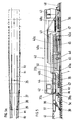
- Figures 4 and 5 show a second embodiment of a heating vehicle followed by an assembly vehicle for fixing the new neutralized rails.
- FIGS. 4a and 5a are top views of the track to illustrate the positions of the old rails R1 and of the new rails R2 and their lateral displacement during substitution, as well as some components of the vehicles.
- FIG. 6 is an enlarged sectional view of the tunnels alone according to FIG. 4.
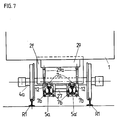
- Figure 7 shows in section, like Figure 6, a variant of the tunnel arrangement.
- FIG. 8 is the control block diagram of a heating installation adapted to the device according to FIGS. 4 and 5.
- Vehicle 1 is designed to roll on the old track R1, in the direction of the arrow, to lift the new rails R2 previously deposited along the track and neutralize them by heating immediately before their installation and, simultaneously, to detach the old rails R1 from the way.
- the vehicle 1 comprises a body 2 supported by a front bogie 3 with two axles 3a and by a rear bogie 4 also with two axles 4a. Between these axles 3a, 4a are installed the two heating tunnels 5, 5 ', one for each row of new rails R2 ( Figure 2).
- these two tunnels 5, 5 ′ are mounted in common frames 6 arranged above the center of the track and suspended below the body 2. They are formed by two side walls 6a separated by a common central wall 6b. The three walls of the frame meet at their upper part and, at determined intervals, are extended by uprights 6c suspended from the body 2, such that the location of the tunnels is centered relative to the body 2 and therefore relative to the way.
- the rails to be neutralized R2 are heated by high frequency induction; for this purpose, the rails R2 pass inside inductors in the form of coils 12 to a turn connected to inverters, and move on guide rollers 7 fixed in the walls 6a, 6b of the tunnels 5, 5 'between the inductors.
- the arrangement of these tunnels 5, 5 ′ is such that the trajectory of the rails R2 to be neutralized is located below the axles 3a, 4a, at a distance from the ballast of between 20 to 40 cm, preferably between 25 and 30 cm. Thanks to this arrangement, it is necessary to avoid having to lift the rails very high and above all above the axles, which facilitates the work and the guiding of the rails.
- retractable nacelles 9, 10 suspended from the vehicle body 2 by jacks 9a, 10a and on which there are automatic or manual stain removal stations , for example automatic screwdrivers 9b, 10b and rolling seats 9c, 10c for workers who remove the fasteners or release the fastenings of the old rails to the sleepers.
- gripping means 8 of the new rails R2 previously disposed in the center of the track or on either side of the track. These gripping means a make it possible to grasp and introduce these rails R2 into the opening before the heating tunnels 5, 5 ′.
- rail clamps 11 which grip the new heated rails R2 at the exit of the tunnels 5, 5 'and guide them on the track where, after the old rails R1 have been removed, they will be laid and then fixed on the sleepers by known means.
- This heating installation mounted on the heating vehicle 1, comprises a heating zone formed by several inductors distributed in each tunnel 5, 5 '.
- inductors 12, 13, 14, arranged one after the other which are formed, in a manner known per se, by a coil with a coil made of hollow copper tube, with a length of 1m each.
- inductor modules of similar construction prefabricated, which makes it possible to compose heating zones of desired length by varying the number of these modules as required.
- the inductors 12, 13, 14 are supplied by two inverters 15, 16 with a power of 100 KW respectively 200 KW and 1000 Hz.
- the inductor 12 is connected to the inverter 15 of 100 KW and the inductors 13, 14 are connected to the 200 KW inverter 16, which allows flexibility in temperature regulation.
- a heating installation is provided with three inductor modules in each of the tunnels 5, 5 ′ illustrated in FIGS. 1 and 2, and crossed as described previously by each row of new rails R2.
- the inverters 15, 16 are connected to an electronic control unit 17.
- the devices 18 for measuring the running speed of the rails R2 relative to the vehicle 1 and sensors 19 for measuring the temperature of the rails before their exposure to heating.
- the distance ZF of the new rails R2 has been indicated at a distance L from the end of the heating zone, therefore from the rear end of the inductor 14. Over this distance L are installed, at regular intervals, several sensors 20 for measuring the temperature of the rails which capture the slow cooling of the rail which occurs.
- the rear end of the last inductor 14 coincides with the rear end of the tunnel 5, 5 '.
- this unit 17 also receives external information by an input unit 21 and set values by an input unit 22 via an operator control interface 23 adapted to personnel.
- the external information includes all the essential external factors, namely the profile of the rails, the type of steel from which the rails are made, the outside temperature and, if applicable, other factors which could influence the cooling speed of the rails (rain, wind, etc.)
- a device for printing protocols 24 and an optical unit 25 for viewing the temperature profile and the state of the process.
- the electronic control unit 17 includes the processing of temperature measurements, the regulation of the heating stations, the management and the control of the process as a function of the values of the temperature of the rails before their exposure to heating, of the speed of travel of the heating elements with respect to the rails, from the value of the change in temperature of the rails after heating up to the time of their attachment to the track.
- the distance L is important and will be chosen in such a way that, for a given speed of travel of the heating elements, the temperature difference between the surface and the core of the new rails does not exceed a determined value and that the temperature of the new rails at the ZF fixing zone corresponds, with given tolerances, to the desired temperature.
- the neutralization temperature during fixation should be 25 ° C ⁇ 0.5 ° C.
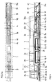
- Figures 4 and 5 show, as a preferred example, a second embodiment of a heating vehicle 1 having shorter heating tunnels 5a, 5b, followed by a mounting vehicle 2 of the new rails.
- the parts of the heating vehicle 1 which correspond to the parts of the first example have the same reference signs. In this case, the heating tunnels are shorter.
- the vehicle 1 (FIG. 4) fitted with a front bogie 3 and a rear bogie 4 rolls on the old rails R1 and comprises a box 2 comprising a cabin 2a, compartments 2b for inverters which supply the inductors of each tunnel high frequency heating, compartments 2c for the refrigeration units which cool the inductors, a tank 2d for the fuel oil, generator groups 2e which supply the inverters, as well as groups of capacitors 2f assigned to the inductors.
- a box 2 comprising a cabin 2a, compartments 2b for inverters which supply the inductors of each tunnel high frequency heating, compartments 2c for the refrigeration units which cool the inductors, a tank 2d for the fuel oil, generator groups 2e which supply the inverters, as well as groups of capacitors 2f assigned to the inductors.
- the new R2 rails are gripped at the head of the vehicle 1 by gripping means 8 and placed on the guide rollers 28 fixed to the chassis of the vehicle and distributed along the latter so that the new rails R2 can pass under the axles 3a, 4a and between the wheels of the bogies 3 and 4.
- the heating tunnels are installed in the area of the rear end of the vehicle 1 in the middle of the track. In the case under consideration they are divided into two parts 5a, 5b fixed to the frame 29, one located before and the other after the rear bogie 4.
- Part 5a comprises two inductor units each having a length of 1 m, and therefore is only 2 m long, while part 5b only has one inductor which is 1 m long.
- Each inductor 12 has the form of a coil with a turn and is connected to a group of capacitors, the oscillating circuit formed by this coil and these capacitors being supplied by inverters. Due to the short length of the tunnel, the R2 rails do not need to be guided inside the tunnel, but can pass it freely.
- each part of the tunnel comprises two sections placed side by side, one for each row of rails, as shown in FIG. 6 for the parts 5a, 5a ', provided with inductors 12 surrounding the two rails R2.
- each part of the tunnels can be provided with rollers 7a which rest and roll on the rails R2 passing this part, these rollers being installed before and after the inductors, respectively between the inductors.
- the parts of the tunnels are suspended from the chassis 29 so that they are somewhat mobile relative to the chassis to allow them to adjust themselves.
- each rail file the two sections 5a, 5a 'of the tunnel provided for each rail file are slightly spaced from each other, connected by a cross member 27 and suspended from the frame 29 by jacks 29a which allow them to be lifted when walking high.
- Each tunnel is provided not only with rollers 7a which rest on the rails R2, but also on either side of each rail, rollers 7b providing lateral guidance.
- spotting stations are provided on two nacelles 9, 10 suspended from a frame 29; these nacelles are equipped with tools for removing fasteners such as automatic spanners 9b, 10b and are fitted with wheels 9d, 10d to roll on the rails R1.
- the vehicle 1 has rail guides 33 for the old released rails R1, a cantilever frame 30 carrying an adjustable support 31 provided with rail clamps 31a which lift the rails R1 ( Figure 4) and move them apart ( Figure 4a), as well as a track 32 rolling on the sleepers to prevent them from coming out of the ballast when lifting the rails R1.
- the frame 30 can be moved towards the interior of the vehicle thanks to the rollers 30a rolling on slides of the frame 29.
- the mounting vehicle 40 ( Figure 5) having the bogies 35 and 36 rolls on the new rails R2 which are placed in their correct position on the crosspieces at the front of the bogie 35.
- the vehicle has at the head a frame 37 cantilevered with an adjustable support 38 carrying rail clamps 39 to spread the rails R2 towards the fixing positions, as shown in the Figure 5a.
- the frame 37 can be moved towards the interior of the vehicle by means of the rollers 37a rolling on slides of the chassis 40a.
- auxiliary heating tunnel 5c positioned at the head of the said vehicle and covering the rails R2 from above, as well as other rail clamps 39a for positioning these rails R2 on the sleepers T.
- This auxiliary tunnel 5c only comes into operation in the event of work being interrupted, to warm up the R2 rails already out of the tunnel 5a, 5b before they are fixed.
- a connection 41 between vehicles 1 and 40 comprising an electric line and a cooling pipe is used to supply this part 5c of the tunnel.
- the vehicle 40 further comprises front 42 and rear 43 cabins, a generator group 44, as well as mounting stations on the two nacelles 45. These nacelles are suspended from the chassis 40a and provided with tools for mounting the fasteners, in particular automatic spanners 46, as well as wheels 45a for running on the rails R2.
- the old rails R1 are guided by guide rollers 47 and deposited next to the track as shown in Figure 5a.
- means 48 for picking up the fasteners removed by the stain removal stations of the vehicle 1 and deposited on the track. These fasteners are transported by conveyors 48a to storage places 49 and by conveyors 50 to the attachment stations on the nacelles 45.
- Figure 8 shows the installation block diagram intended for vehicles 1 and 40 according to Figures 4 and 5 and is very similar to that illustrated in Figure 3.
- the same units are identified by the same reference signs and will not be re-described.
- the modifications compared to Figure 3 are as follows:
- An inverter 15a pe of 50 kW, supplies the two inductors 12, 13 mounted in each part 5a of the tunnels, and an inverter 16a, pe of 100 kW, supplies the inductor 14 mounted in each part 5b of the tunnels or else an inductor auxiliary 26 mounted in each part 5c of the tunnels at the head of the vehicle 40.
- An inverter 27 makes it possible to connect the inverter 16a to the inductor 14 or 26.
- the inverters in this case work at 2 kHz.
- Each inductor, designed as a module, is formed by a coil with a hollow coil and its length is 1 m.
- the method according to the invention could be implemented by installations other than those which have just been described, in particular the heat source could be different.
- the high frequency induction heating which is the preferred heating could in particular be replaced by an electric resistance heating or by a gas heating.
Landscapes
- Engineering & Computer Science (AREA)
- Architecture (AREA)
- Civil Engineering (AREA)
- Structural Engineering (AREA)
- Mechanical Engineering (AREA)
- Train Traffic Observation, Control, And Security (AREA)
- Machines For Laying And Maintaining Railways (AREA)
- General Induction Heating (AREA)
- Tunnel Furnaces (AREA)
- Signal Processing For Digital Recording And Reproducing (AREA)
- Superconductors And Manufacturing Methods Therefor (AREA)
- Railway Tracks (AREA)
- Electric Propulsion And Braking For Vehicles (AREA)
- Escalators And Moving Walkways (AREA)
Applications Claiming Priority (4)
| Application Number | Priority Date | Filing Date | Title |
|---|---|---|---|
| CH235090 | 1990-07-13 | ||
| CH2350/90 | 1990-07-13 | ||
| CH1869/91 | 1991-06-25 | ||
| CH186991A CH685636A5 (fr) | 1991-06-25 | 1991-06-25 | Procédé et installation de neutralisation en voie des rails de chemin de fer. |
Publications (2)
| Publication Number | Publication Date |
|---|---|
| EP0467833A1 EP0467833A1 (fr) | 1992-01-22 |
| EP0467833B1 true EP0467833B1 (fr) | 1994-03-16 |
Family
ID=25688886
Family Applications (2)
| Application Number | Title | Priority Date | Filing Date |
|---|---|---|---|
| EP91810530A Expired - Lifetime EP0467833B1 (fr) | 1990-07-13 | 1991-07-05 | Procédé de neutralisation en voie des rails de chemin de fer |
| EP91810529A Expired - Lifetime EP0466652B1 (fr) | 1990-07-13 | 1991-07-05 | Dispositif pour la neutralisation des nouveaux rails des voies ferrées |
Family Applications After (1)
| Application Number | Title | Priority Date | Filing Date |
|---|---|---|---|
| EP91810529A Expired - Lifetime EP0466652B1 (fr) | 1990-07-13 | 1991-07-05 | Dispositif pour la neutralisation des nouveaux rails des voies ferrées |
Country Status (8)
| Country | Link |
|---|---|
| US (1) | US5237143A (da) |
| EP (2) | EP0467833B1 (da) |
| JP (1) | JPH04254601A (da) |
| AT (2) | ATE127558T1 (da) |
| CA (1) | CA2046941A1 (da) |
| DE (2) | DE69112730T2 (da) |
| DK (2) | DK0466652T3 (da) |
| ES (1) | ES2051104T3 (da) |
Families Citing this family (21)
| Publication number | Priority date | Publication date | Assignee | Title |
|---|---|---|---|---|
| AT401943B (de) * | 1992-08-21 | 1996-12-27 | Plasser Bahnbaumasch Franz | Kontinuierlich verfahrbare gleisstopfmaschine |
| CH689643A5 (fr) * | 1994-02-18 | 1999-07-30 | Speno International | Installation pour le reprofilage des rails d'une voie ferrée. |
| CA2121651C (en) * | 1994-04-19 | 1999-11-30 | Darrell Doherty | Track and rail-form slider combination |
| US5927209A (en) * | 1997-04-14 | 1999-07-27 | Harsco Corporation | Rail heating and clip applicator |
| EP1185737A1 (de) * | 1999-06-17 | 2002-03-13 | GSG Knape Gleissanierung GmbH | Verfahren zur herstellung einer fahrbahn für schienenfahrzeuge |
| US6515249B1 (en) * | 2000-09-29 | 2003-02-04 | Harsco Technologies Corporation | Method of railroad rail repair |
| US7544918B2 (en) * | 2004-05-17 | 2009-06-09 | Herzog Kenneth J | Conveyor speed monitor |
| FR2883891B1 (fr) * | 2005-03-31 | 2007-06-01 | Europ De Travaux Ferroviaires | Procede d'optimisation de la substitution de rails de chemin de fer anciens par des rails de chemin de fer neufs |
| FR2899249B1 (fr) * | 2006-04-04 | 2012-10-05 | Europ De Travaux Ferroviaires Etf | Procede et dispositif de renouvellement de rail ferroviaire en continu |
| WO2010109837A1 (ja) * | 2009-03-27 | 2010-09-30 | 新日本製鐵株式会社 | レール溶接部の冷却装置および冷却方法 |
| ES2384150B1 (es) * | 2009-12-28 | 2013-10-10 | Ferrovial Agromán S.A. | Sistema para descarga de carriles. |
| CN101956346A (zh) * | 2010-03-26 | 2011-01-26 | 孟祥厚 | 铁轨热处理用感应加热装置 |
| US8651393B2 (en) * | 2010-03-26 | 2014-02-18 | Holland, L.P. | Repair insert for repairing metallic structure |
| CN101929114B (zh) * | 2010-08-26 | 2012-02-08 | 中国科学院长春光学精密机械与物理研究所 | 基于火车运行对钢轨硬化的光学装置的应用方法 |
| FR3020073B1 (fr) | 2015-07-27 | 2017-01-13 | Matisa Materiel Ind Sa | Procede de renouvellement de voies ferrees et dispositif pour sa mise en oeuvre |
| CN105525545B (zh) * | 2016-01-18 | 2018-01-30 | 重庆交通大学 | 有砟轨道自动控制换轨机器人 |
| CN107034750A (zh) * | 2017-05-18 | 2017-08-11 | 西南交通大学 | 轨枕立螺栓拔出设备 |
| FR3066508B1 (fr) * | 2017-05-22 | 2021-02-12 | Matisa Materiel Ind Sa | Procede de pose d’un rail de voie ferree, comportant un chauffage du rail, et train de travaux pour la mise en œuvre du procede de pose |
| CN108825874A (zh) * | 2018-08-02 | 2018-11-16 | 杭州吉宝传动设备有限公司 | 一种恒温拖链及其操作方法 |
| FR3086677B1 (fr) * | 2018-10-02 | 2020-10-30 | Matisa Materiel Ind Sa | Procede d’immobilisation d’un rail de voie ferree avec conditionnement thermique d’une portion de rail, et machine ferroviaire associee |
| FR3093115B1 (fr) * | 2019-02-21 | 2022-07-15 | Matisa Materiel Ind Sa | Dispositif mobile de chauffage d’un rail de voie ferrée par lampes électriques à rayonnement infrarouge et procédé de chauffage associé |
Family Cites Families (28)
| Publication number | Priority date | Publication date | Assignee | Title |
|---|---|---|---|---|
| DE1041516B (de) * | 1957-01-23 | 1958-10-23 | Elektro Thermit Gmbh | Auf den Schienen laengs bewegliche, tunnelartige Waermekammer zur kuenst-lichen Erwaermung von Schienen, insbesondere bei der Herstellung lueckenloser Gleise |
| FR1363164A (fr) * | 1963-02-06 | 1964-06-12 | Sncf | Dispositif pour le chargement et le transport de rails en tronçons longs d'un seul tenant ou en éléments éclissés |
| US3566796A (en) * | 1967-03-28 | 1971-03-02 | Penn Central Co | Rail temperature regulating apparatus |
| AT305331B (de) * | 1967-06-29 | 1973-02-26 | Plasser Bahnbaumasch Franz | Vorrichtung zum kontinuierlich fortschreitenden Erneuern von Gleisen |
| US3896734A (en) * | 1967-12-29 | 1975-07-29 | Plasser Bahnbaumasch Franz | Apparatus for continuously laying track |
| US3505492A (en) * | 1968-06-20 | 1970-04-07 | Ajax Magnethermic Corp | Method and apparatus for induction heating of slabs |
| AT303788B (de) * | 1970-08-28 | 1972-12-11 | Plasser Bahnbaumasch Franz | Verfahren und Eirichtung zur Kontrolle und Regelung der Temperatur von Schienensträgen |
| AT323786B (de) * | 1971-10-04 | 1975-07-25 | Plasser Bahnbaumasch Franz | Einrichtung zur messung und aufzeichnung einer zurückgelegten strecke |
| US3705285A (en) * | 1971-11-05 | 1972-12-05 | Growth Intern Inc | Mobile apparatus for the induction heating of metal ingots |
| JPS5249204B2 (da) * | 1973-10-01 | 1977-12-15 | ||
| JPS5317509A (en) * | 1976-08-03 | 1978-02-17 | Nippon Kokan Kk <Nkk> | Method and apparatus for induction heating of metallic material |
| AT358086B (de) * | 1977-05-06 | 1980-08-25 | Plasser Bahnbaumasch Franz | Einrichtung zum auswechseln der schienen- befestigungsmittel und gegebenenfalls der schienen eines gleises |
| FR2399299A1 (fr) * | 1977-08-05 | 1979-03-02 | Tocco Stel | Procede et dispositif de soudage bout a bout par induction de pieces metalliques, notamment de section irreguliere |
| AT357594B (de) * | 1977-12-28 | 1980-07-25 | Plasser Bahnbaumasch Franz | Fahrbare abbrenn-stumpf-schienenschweiss- maschine mit schweisswulst-abtragvorrichtung |
| AT357595B (de) * | 1977-12-28 | 1980-07-25 | Plasser Bahnbaumasch Franz | Fahrbare schienenschweissmaschine |
| US4195805A (en) * | 1978-03-20 | 1980-04-01 | Keep Henry W Jr | Railroad switch heater |
| GB1592881A (en) * | 1978-04-06 | 1981-07-08 | Canron Corp | Thermal expansion shifting of rail |
| AT362818B (de) * | 1979-10-05 | 1981-06-25 | Plasser Bahnbaumasch Franz | Gleisbearbeitungs- bzw. -transportfahrzeug mit veraenderlicher radlastverteilung |
| US4315129A (en) * | 1979-10-15 | 1982-02-09 | Omark Industries, Inc. | Mobile apparatus for welding studs to rail base plates |
| US4324184A (en) * | 1980-03-24 | 1982-04-13 | Universal Mobility, Inc. | Temperature control system and method for an automated guideway transit system |
| US4414454A (en) * | 1981-08-13 | 1983-11-08 | H. A. Schlatter Ag | Method of welding continuous rails and apparatus therefor |
| US4429845A (en) * | 1982-04-26 | 1984-02-07 | Emerson Electric Co. | Rail track heaters |
| IT1201813B (it) * | 1986-09-22 | 1989-02-02 | Danieli Off Mecc | Dispositivo posizionatore meccanico |
| AT389541B (de) * | 1987-07-23 | 1989-12-27 | Plasser Bahnbaumasch Franz | Schwellenauswechsel-maschine |
| AT389540B (de) * | 1987-07-23 | 1989-12-27 | Plasser Bahnbaumasch Franz | Anlage bzw. maschinenkombination und verfahren zum fortschreitenden teilweisen schwellen-auswechseln eines gleises |
| DE3804585C1 (da) * | 1988-02-13 | 1989-04-27 | Daimler-Benz Aktiengesellschaft, 7000 Stuttgart, De | |
| EP0355240B1 (fr) * | 1988-08-18 | 1992-12-23 | Scheuchzer S.A. | Train de renouvellement d'une voie de chemin de fer |
| US5024380A (en) * | 1990-01-05 | 1991-06-18 | Bethlehem Steel Corporation | Method and apparatus for continuous welded rail |
-
1991
- 1991-07-05 EP EP91810530A patent/EP0467833B1/fr not_active Expired - Lifetime
- 1991-07-05 DE DE69112730T patent/DE69112730T2/de not_active Expired - Fee Related
- 1991-07-05 DK DK91810529.7T patent/DK0466652T3/da active
- 1991-07-05 EP EP91810529A patent/EP0466652B1/fr not_active Expired - Lifetime
- 1991-07-05 AT AT91810529T patent/ATE127558T1/de not_active IP Right Cessation
- 1991-07-05 ES ES91810530T patent/ES2051104T3/es not_active Expired - Lifetime
- 1991-07-05 DK DK91810530.5T patent/DK0467833T3/da not_active Application Discontinuation
- 1991-07-05 DE DE69101412T patent/DE69101412T2/de not_active Expired - Fee Related
- 1991-07-05 AT AT91810530T patent/ATE103025T1/de not_active IP Right Cessation
- 1991-07-09 US US07/727,591 patent/US5237143A/en not_active Expired - Lifetime
- 1991-07-12 CA CA002046941A patent/CA2046941A1/en not_active Abandoned
- 1991-07-15 JP JP3266722A patent/JPH04254601A/ja active Pending
Also Published As
| Publication number | Publication date |
|---|---|
| EP0466652A1 (fr) | 1992-01-15 |
| DE69112730T2 (de) | 1996-04-18 |
| US5237143A (en) | 1993-08-17 |
| DK0467833T3 (da) | 1994-08-01 |
| DE69112730D1 (de) | 1995-10-12 |
| JPH04254601A (ja) | 1992-09-09 |
| EP0467833A1 (fr) | 1992-01-22 |
| ES2051104T3 (es) | 1994-06-01 |
| ATE103025T1 (de) | 1994-04-15 |
| DK0466652T3 (da) | 1996-01-22 |
| EP0466652B1 (fr) | 1995-09-06 |
| DE69101412T2 (de) | 1994-10-13 |
| DE69101412D1 (de) | 1994-04-21 |
| ATE127558T1 (de) | 1995-09-15 |
| CA2046941A1 (en) | 1992-01-14 |
Similar Documents
| Publication | Publication Date | Title |
|---|---|---|
| EP0467833B1 (fr) | Procédé de neutralisation en voie des rails de chemin de fer | |
| EP0466651B1 (fr) | Dispositif pour la substitution des rails des voies de chemins de fer | |
| FR2681082A1 (fr) | Procede pour le renouvellement d'une voie ferree et agencement de machine pour la mise en óoeuvre du procede. | |
| EP0431092B1 (fr) | Procédé pour le soudage en continu de tronçons de rail, et rame equipée pour sa mise en oeuvre | |
| EP2684756B1 (fr) | Installation de transport par câble | |
| CA2015238A1 (fr) | Procede et dispositif pour bomber et tremper les feuilles de verre | |
| EP0551798A1 (fr) | Dispositif de substitution et de neutralisation des rails des voies de chemin de fer | |
| CH685636A5 (fr) | Procédé et installation de neutralisation en voie des rails de chemin de fer. | |
| WO2007118977A2 (fr) | Procede et dispositif de renouvellement de rail ferroviaire en continu | |
| EP4179147A1 (fr) | Procédés initial et final de pose de longs rails | |
| WO2017001068A1 (fr) | Machine d'étirage de film et son procédé de démarrage | |
| EP0467001B1 (fr) | Train de pose des nouvelles voies ferrées et procédé pour la pose de celles-ci utilisant un tel train | |
| EP0707082B1 (de) | Einrichtung zur Warmbehandlung von Stahldraht | |
| CH685779A5 (fr) | Dispositif pour la substitution des rails des voies de chemins de fer. | |
| JP4779249B2 (ja) | 真空誘導炉設備 | |
| BE891760A (fr) | Four a rechauffer les brames, les billettes et les flans | |
| FR2510139A1 (fr) | Appareil de rechauffage des extremites de tubes en acier a refoulements exterieurs | |
| KR102076504B1 (ko) | 연속 공정이 이루어지는 브레이징 장치 | |
| FR2701493A1 (fr) | Installation de décapage d'une bande métallique. | |
| ES2249688T3 (es) | Procedimiento y dispositivo para la laminacion continua ininterrumpida de productos de redondos y varillas. | |
| EP4179148A1 (fr) | Procédé de renouvellement de rails d'une voie ferrée par des longs rails nouveaux, et train de travaux associé | |
| JPH08318853A (ja) | 横移動トラバーサ方式 | |
| CA3130407C (fr) | Dispositif mobile de chauffage d'un rail de voie ferree par lampes electriques a rayonnement infrarouge et procede de chauffage associe | |
| FR2713262A1 (fr) | Dispositif pour déplacer des véhicules sur des voies orthogonales dans un parking automatique. | |
| EP0451075A1 (fr) | Dispositif pour chauffer des pièces métalliques par induction |
Legal Events
| Date | Code | Title | Description |
|---|---|---|---|
| PUAI | Public reference made under article 153(3) epc to a published international application that has entered the european phase |
Free format text: ORIGINAL CODE: 0009012 |
|
| AK | Designated contracting states |
Kind code of ref document: A1 Designated state(s): AT BE CH DE DK ES FR GB IT LI LU NL SE |
|
| 17P | Request for examination filed |
Effective date: 19920709 |
|
| 17Q | First examination report despatched |
Effective date: 19921026 |
|
| RTI1 | Title (correction) | ||
| RAP1 | Party data changed (applicant data changed or rights of an application transferred) |
Owner name: SCHEUCHZER S.A. |
|
| GRAA | (expected) grant |
Free format text: ORIGINAL CODE: 0009210 |
|
| AK | Designated contracting states |
Kind code of ref document: B1 Designated state(s): AT BE CH DE DK ES FR GB IT LI LU NL SE |
|
| REF | Corresponds to: |
Ref document number: 103025 Country of ref document: AT Date of ref document: 19940415 Kind code of ref document: T |
|
| REF | Corresponds to: |
Ref document number: 69101412 Country of ref document: DE Date of ref document: 19940421 |
|
| ITF | It: translation for a ep patent filed | ||
| REG | Reference to a national code |
Ref country code: ES Ref legal event code: FG2A Ref document number: 2051104 Country of ref document: ES Kind code of ref document: T3 |
|
| GBT | Gb: translation of ep patent filed (gb section 77(6)(a)/1977) |
Effective date: 19940621 |
|
| PG25 | Lapsed in a contracting state [announced via postgrant information from national office to epo] |
Ref country code: LU Free format text: LAPSE BECAUSE OF NON-PAYMENT OF DUE FEES Effective date: 19940731 |
|
| REG | Reference to a national code |
Ref country code: DK Ref legal event code: T3 |
|
| PLBE | No opposition filed within time limit |
Free format text: ORIGINAL CODE: 0009261 |
|
| STAA | Information on the status of an ep patent application or granted ep patent |
Free format text: STATUS: NO OPPOSITION FILED WITHIN TIME LIMIT |
|
| EAL | Se: european patent in force in sweden |
Ref document number: 91810530.5 |
|
| 26N | No opposition filed | ||
| PGFP | Annual fee paid to national office [announced via postgrant information from national office to epo] |
Ref country code: SE Payment date: 19990707 Year of fee payment: 9 |
|
| PGFP | Annual fee paid to national office [announced via postgrant information from national office to epo] |
Ref country code: DK Payment date: 19990714 Year of fee payment: 9 |
|
| PG25 | Lapsed in a contracting state [announced via postgrant information from national office to epo] |
Ref country code: DK Free format text: LAPSE BECAUSE OF NON-PAYMENT OF DUE FEES Effective date: 20000705 |
|
| PG25 | Lapsed in a contracting state [announced via postgrant information from national office to epo] |
Ref country code: SE Free format text: LAPSE BECAUSE OF NON-PAYMENT OF DUE FEES Effective date: 20000706 |
|
| EUG | Se: european patent has lapsed |
Ref document number: 91810530.5 |
|
| REG | Reference to a national code |
Ref country code: DK Ref legal event code: EBP |
|
| PGFP | Annual fee paid to national office [announced via postgrant information from national office to epo] |
Ref country code: ES Payment date: 20010719 Year of fee payment: 11 |
|
| REG | Reference to a national code |
Ref country code: GB Ref legal event code: IF02 |
|
| PGFP | Annual fee paid to national office [announced via postgrant information from national office to epo] |
Ref country code: GB Payment date: 20020703 Year of fee payment: 12 |
|
| PG25 | Lapsed in a contracting state [announced via postgrant information from national office to epo] |
Ref country code: ES Free format text: LAPSE BECAUSE OF NON-PAYMENT OF DUE FEES Effective date: 20020706 |
|
| PGFP | Annual fee paid to national office [announced via postgrant information from national office to epo] |
Ref country code: NL Payment date: 20020730 Year of fee payment: 12 |
|
| PGFP | Annual fee paid to national office [announced via postgrant information from national office to epo] |
Ref country code: BE Payment date: 20020919 Year of fee payment: 12 |
|
| PG25 | Lapsed in a contracting state [announced via postgrant information from national office to epo] |
Ref country code: GB Free format text: LAPSE BECAUSE OF NON-PAYMENT OF DUE FEES Effective date: 20030705 |
|
| PG25 | Lapsed in a contracting state [announced via postgrant information from national office to epo] |
Ref country code: BE Free format text: LAPSE BECAUSE OF NON-PAYMENT OF DUE FEES Effective date: 20030731 |
|
| BERE | Be: lapsed |
Owner name: S.A. *SCHEUCHZER Effective date: 20030731 |
|
| PG25 | Lapsed in a contracting state [announced via postgrant information from national office to epo] |
Ref country code: NL Free format text: LAPSE BECAUSE OF NON-PAYMENT OF DUE FEES Effective date: 20040201 |
|
| GBPC | Gb: european patent ceased through non-payment of renewal fee |
Effective date: 20030705 |
|
| NLV4 | Nl: lapsed or anulled due to non-payment of the annual fee |
Effective date: 20040201 |
|
| REG | Reference to a national code |
Ref country code: ES Ref legal event code: FD2A Effective date: 20030811 |
|
| PGFP | Annual fee paid to national office [announced via postgrant information from national office to epo] |
Ref country code: DE Payment date: 20070726 Year of fee payment: 17 |
|
| PGFP | Annual fee paid to national office [announced via postgrant information from national office to epo] |
Ref country code: IT Payment date: 20070730 Year of fee payment: 17 |
|
| PG25 | Lapsed in a contracting state [announced via postgrant information from national office to epo] |
Ref country code: DE Free format text: LAPSE BECAUSE OF NON-PAYMENT OF DUE FEES Effective date: 20090203 |
|
| PG25 | Lapsed in a contracting state [announced via postgrant information from national office to epo] |
Ref country code: IT Free format text: LAPSE BECAUSE OF NON-PAYMENT OF DUE FEES Effective date: 20080705 |
|
| PGFP | Annual fee paid to national office [announced via postgrant information from national office to epo] |
Ref country code: CH Payment date: 20100809 Year of fee payment: 20 |
|
| PGFP | Annual fee paid to national office [announced via postgrant information from national office to epo] |
Ref country code: FR Payment date: 20100812 Year of fee payment: 20 Ref country code: AT Payment date: 20100617 Year of fee payment: 20 |
|
| REG | Reference to a national code |
Ref country code: CH Ref legal event code: PL |