EP0467082B1 - Verfahren und Vorrichtung zur Gewährleistung der Arbeitssicherheit - Google Patents
Verfahren und Vorrichtung zur Gewährleistung der Arbeitssicherheit Download PDFInfo
- Publication number
- EP0467082B1 EP0467082B1 EP91109984A EP91109984A EP0467082B1 EP 0467082 B1 EP0467082 B1 EP 0467082B1 EP 91109984 A EP91109984 A EP 91109984A EP 91109984 A EP91109984 A EP 91109984A EP 0467082 B1 EP0467082 B1 EP 0467082B1
- Authority
- EP
- European Patent Office
- Prior art keywords
- sensor
- status
- safe
- work
- output signal
- Prior art date
- Legal status (The legal status is an assumption and is not a legal conclusion. Google has not performed a legal analysis and makes no representation as to the accuracy of the status listed.)
- Expired - Lifetime
Links
- 238000000034 method Methods 0.000 title claims description 16
- 238000004804 winding Methods 0.000 claims description 20
- 238000009877 rendering Methods 0.000 claims description 3
- 229920006395 saturated elastomer Polymers 0.000 claims description 3
- 230000003287 optical effect Effects 0.000 description 15
- 238000010586 diagram Methods 0.000 description 11
- 238000001514 detection method Methods 0.000 description 10
- 239000003990 capacitor Substances 0.000 description 5
- 238000012544 monitoring process Methods 0.000 description 5
- 230000010355 oscillation Effects 0.000 description 5
- 238000013461 design Methods 0.000 description 2
- 238000011161 development Methods 0.000 description 2
- 230000018109 developmental process Effects 0.000 description 2
- 230000007257 malfunction Effects 0.000 description 2
- 230000003321 amplification Effects 0.000 description 1
- 238000010420 art technique Methods 0.000 description 1
- 230000000903 blocking effect Effects 0.000 description 1
- 210000004556 brain Anatomy 0.000 description 1
- 239000000470 constituent Substances 0.000 description 1
- 238000004880 explosion Methods 0.000 description 1
- 238000012423 maintenance Methods 0.000 description 1
- 238000003199 nucleic acid amplification method Methods 0.000 description 1
- 238000012546 transfer Methods 0.000 description 1
Images

Classifications
-
- F—MECHANICAL ENGINEERING; LIGHTING; HEATING; WEAPONS; BLASTING
- F16—ENGINEERING ELEMENTS AND UNITS; GENERAL MEASURES FOR PRODUCING AND MAINTAINING EFFECTIVE FUNCTIONING OF MACHINES OR INSTALLATIONS; THERMAL INSULATION IN GENERAL
- F16P—SAFETY DEVICES IN GENERAL; SAFETY DEVICES FOR PRESSES
- F16P3/00—Safety devices acting in conjunction with the control or operation of a machine; Control arrangements requiring the simultaneous use of two or more parts of the body
- F16P3/12—Safety devices acting in conjunction with the control or operation of a machine; Control arrangements requiring the simultaneous use of two or more parts of the body with means, e.g. feelers, which in case of the presence of a body part of a person in or near the danger zone influence the control or operation of the machine
- F16P3/14—Safety devices acting in conjunction with the control or operation of a machine; Control arrangements requiring the simultaneous use of two or more parts of the body with means, e.g. feelers, which in case of the presence of a body part of a person in or near the danger zone influence the control or operation of the machine the means being photocells or other devices sensitive without mechanical contact
- F16P3/145—Safety devices acting in conjunction with the control or operation of a machine; Control arrangements requiring the simultaneous use of two or more parts of the body with means, e.g. feelers, which in case of the presence of a body part of a person in or near the danger zone influence the control or operation of the machine the means being photocells or other devices sensitive without mechanical contact using magnetic technology
-
- F—MECHANICAL ENGINEERING; LIGHTING; HEATING; WEAPONS; BLASTING
- F16—ENGINEERING ELEMENTS AND UNITS; GENERAL MEASURES FOR PRODUCING AND MAINTAINING EFFECTIVE FUNCTIONING OF MACHINES OR INSTALLATIONS; THERMAL INSULATION IN GENERAL
- F16P—SAFETY DEVICES IN GENERAL; SAFETY DEVICES FOR PRESSES
- F16P3/00—Safety devices acting in conjunction with the control or operation of a machine; Control arrangements requiring the simultaneous use of two or more parts of the body
- F16P3/12—Safety devices acting in conjunction with the control or operation of a machine; Control arrangements requiring the simultaneous use of two or more parts of the body with means, e.g. feelers, which in case of the presence of a body part of a person in or near the danger zone influence the control or operation of the machine
- F16P3/14—Safety devices acting in conjunction with the control or operation of a machine; Control arrangements requiring the simultaneous use of two or more parts of the body with means, e.g. feelers, which in case of the presence of a body part of a person in or near the danger zone influence the control or operation of the machine the means being photocells or other devices sensitive without mechanical contact
- F16P3/144—Safety devices acting in conjunction with the control or operation of a machine; Control arrangements requiring the simultaneous use of two or more parts of the body with means, e.g. feelers, which in case of the presence of a body part of a person in or near the danger zone influence the control or operation of the machine the means being photocells or other devices sensitive without mechanical contact using light grids
Definitions
- the present invention relates to a method and an apparatus for assuring safety of a worker in a work space in accordance with the precharacterizing parts of the claims 1 and 4, respectively.
- a typical conventional safety assuring system for use in such a working system is designed in such a way that an optical signal from an optical radar sensor is emanated onto the working area of the movable section of a machine, and any work involving the movable section of the machine will be stopped when the optical signal is reflected by a worker and received by the sensor, which indicates the presence of a dangerous environment. That is, the conventional safety assuring system is realized based on the concept that work on the machine side should be terminated upon detection of a dangerous condition or environment (man or men present in the work space).
- AU-B-509 999 describes a known electrical safety guarding equipment, wherein the presence of a worker by an optical detection apparatus and the operation of a machine-control apparatus is controlled on the basis of the detection result; whether the operation of said detection apparatus is normal or not is monitored by a monitoring apparatus, and the energization of the machine control apparatus is stopped, when the detection apparatus fails.
- This prior art document fails to disclose a calculation of a logical product of an output of the monitoring apparatus indicative of the normal status of the optical sensor and work-enable signal. Further, the above document does not mention to consider the fail safe of a logical product calculating element.
- US-A-3,805,085 discloses a technique to enable a machinery operation by optically detecting that a worker (e.g. his hands) is present in a safe area.
- a worker e.g. his hands
- US-A-3,805,085 discloses a technique to enable a machinery operation by optically detecting that a worker (e.g. his hands) is present in a safe area.
- a worker e.g. his hands
- the machinery is operated. That is, when the optical sensor does not receive the optical beam, e.g. when the optical beam is accidentally interrupted, the safe status of the worker is indicated.
- the optical beam is not detected due to failure of the optical sensor, there is a possibility that the worker is judged to be in the safe status and thereupon the machinery operation is erroneously enabled.
- US-A-3,742,222 discloses a system utilizing multiple light beams and multiple light sensors for establishing an area of light to detect the presence of an object blocking one or more beams in the area.
- a relay is energized by a logical product output of the detected outputs of the optical sensors and the machinery operation is controlled by an output of a DC-circuit consisting of a contact of the relay and a manual switch.
- the fail-safe characteristic of the AND circuit used for providing the logical product is not disclosed.
- the fail-safe characteristic of the DC-circuit consisting of the contact and the manual switch is not disclosed.
- a safe work assuring method for assuring safety of a worker in a work space where the worker works in cooperation with a machine wherein a safe status of the worker is detected by a sensor and a work executing energy is generated for the work space on a machine side is characterized by the steps of:
- the present method is designed such that work executing energy on the machine side for the work space is generated only when the work enable signal of a logical "1" corresponding to the high energy status is issued, the work enable signal for the high energy status will not be generated even when a sensor for detecting safety fails. In this way collision of a machine with men can be prevented, thus surely assuring safe work environments.
- the work enable signal may be generated only when the sensor detects a safe status in which no workers are present in the work space or when the sensor detects a safe status in which a worker is in a safe space other than the work space.
- the method may be modified in such a way that given that information representing a safe status and a dangerous status are expressed respectively by binary logical values of "1" and "0", an energy status received by the sensor and safety information to be sent based on the energy status coincide with each other as a logical "1". This will result in further improvement of the fail-safe.
- a safe work assuring apparatus for assuring safety of a worker in a work space where the worker works in cooperation with a machine wherein a safe status of the worker is detected by a sensor and a work execution energy is generated for the work space on a machine side when a sensor output signal indicative of a safe status of the worker is generated from the sensor is characterized in that said sensor is adapted for detecting the safe status of the worker by receiving an AC input signal at a high level and for detecting a dangerous status of the worker by receiving the AC input signal at a low level including zero means, amplifying and rectifying an AC signal based on the AC input signal, generating a rectified output signal indicative of the safe status as a logical "1" upon reception of the AC input signal at the high level, generating the rectified output signal indicative of the dangerous status as a logical "0" upon reception of the AC input signal at the low level including zero, and rendering the rectified output signal to a logical "0" when the sensor fails; and a logical product element having two input signals
- the senor generates a work enable signal of a logical "1" corresponding to a high energy status when detecting the safety of a worker in the work space, and the logical product element sends a drive signal for the movable section of the machine to the machine side as its output signal for generation of this work executing energy only upon generation of this work enable signal.
- the sensor fails, therefore, the sensor output represents a low energy status so that the movable section of the machine will not be driven, thus assuring safe work environments.
- the sensor may be designed to detect the safe status upon reception of a logical value of 1 corresponding to the high energy status and output the work enable signal without a negation circuit. Even if the sensor fails, the sensor is prevented from producing an output of a logical "1" corresponding to the high energy status.
- the logical product element may be designed to produce an output only when an input signal of a higher level than that of a power supply voltage is applied to two input terminals of the logical product element. This can provide such a fail-safe measure that the logical product element will not generate an output of a logical "1" corresponding to the high energy status whatever failure occurs in the logical product element, thus ensuring higher safety.
- Fig. 1 shows a model of the man/machine working system according to this embodiment.
- Work space means the space where men (workers) and a movable section of a machine, such as the arm of a robot, alternately work; for example, worker carry work in this space and the machine processes it.
- Machine space and "man space” mean safe space, i.e., space where the movable section of the machine will not collide against the workers or is kept by a safe distance away from the latter.
- the above man/machine working system should be so designed that men enter the work space while at least the machine's movable section is out of the space, or vice versa.
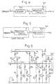
- Fig. 2 illustrates a model of this safe work assuring system.
- Mx, Po, Hx, and Ho are binary logical variables.
- Mx indicates an intention that the movable section of a machine in the machine space will move to the work space in response to a command ("1" for the presence of the intention and "0" for no intention).
- Po represents work executing energy of the machine's movable section in the work space ("1" for energy present and "0” for no energy).
- Hx indicates an intention that men in the man space will move to the work space ("1” for the presence of the intention and "0” for no intention), and Ho work executing energy of men in the work space ("1" for energy present and "0” for no energy).
- the sensor Sh is the eyes of the man, and the logical product element Gh is the man's brain.
- the intention Mx of the movable section of the machine means, for example, a work command issued from a controller provided on the machine side.
- a sensor S m1 and a negation circuit N constitute the sensor Sm in Fig. 3.
- a sensor S m2 detects information of the result of negating the dangerous status S in the negation circuit N, and outputs the work enable signal Pe as the detection result.
- the sensor S m2 corresponds to the sensor Sm in Fig. 3.
- the logical variable S indicating the safety information, the work enable signal Pe and the output signal Po should have such a relationship (unate logical relationship) that at least the logical value will not erroneously become "1".
- a C-MOS type two-input logical product circuit which is used for ordinary logical operations may produce an output of a logical level corresponding to a high energy status when it fails, or may generate an output signal indicating the high energy status even if only one of its two input signals is available.
- This type of logical product circuit cannot therefore serve as a logical product element in the safety system shown in Fig. 3.
- Fig. 6 illustrates an embodiment of a logical product calculating circuit that can serve as the logical product element in Fig. 3.
- R1 to R5 denote resistors, Q1 to Q9 transistors, D, D1 and D2 diodes, and C1 and C2 capacitors.
- Reference characters E is the power supply voltage of the circuit, 1 and 2 represent input terminals, and OUT denotes an output terminal.
- this calculating circuit When no input voltage is applied to the input terminals 1 and 2, the transistors Q1 and Q5 are in an ON status. When a predetermined voltage is applied to both input terminals 1 and 2, the transistors Q1 to Q7 are repeatedly turned on and off in a specific order to cause oscillation: Q1 OFF ⁇ Q2 OFF ⁇ Q3 ONE ⁇ Q4 OFF ⁇ Q5 OFF ⁇ Q6 OFF ⁇ Q7 ON ⁇ Q1 ON ⁇ Q2 ON ⁇ Q3 OFF ⁇ Q4 ON ⁇ Q5 ON ⁇ Q6 ON ⁇ Q7 OFF ⁇ ...
- the oscillation output is transferred via the diode D to the transistors Q8 and Q9 for amplification.
- the amplified output is sent to a voltage multiplying rectifier, constituted by the capacitors C1 and C2 and diodes D1 and D2, and is superimposed on the power supply voltage E there.
- the resultant output is sent as a DC output through the output terminal OUT.
- the circuit has a logical product calculating function.
- this oscillation circuit has a characteristic that it cannot oscillate when any of the resistors R1-R5 is cut or any of the transistors Q1 - Q9 fails.
- the oscillation circuit has a fail-safe characteristic that it will not provide a DC output is no input signals are applied to both of the two input terminal, and will not produce an output in response to the input signal to one of the input terminals alone.
- the reason to superimpose the amplified output on the power supply voltage E in the rectifying circuit is to provide the input condition to permit the output from the logical product element to oscillate at the subsequent stage when the same logical product elements are cascade-connected.
- Figs. 7 and 8 illustrate embodiments of the sensor for detecting safety information.
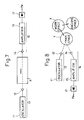
- Fig. 7 shows an embodiment of the sensor in the case of directly monitoring the status of space (work space) the safety in which should be secured.
- the senor comprises a light-emitting unit 13, a light-receiving unit 16 and a rectifying circuit 17.
- the rectifying circuit 17 rectifies the AC output from the light-receiving unit 16 and produces a DC output signal Pe.
- Fig. 8 In contrast to the above embodiment in Fig. 7 for directly monitoring the status in the work space X the safety in which should be secured, the embodiment shown in Fig. 8 is designed for the case of detecting if any man returns to the man space Y or indirectly monitoring the work space X. Like reference numerals as used in Fig. 7 are used to denote corresponding or identical elements in Fig. 8 to avoid their otherwise redundant description.
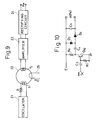
- the sensor in Fig. 9 is effective in a safety system which cuts off the power supply when the current erroneously flows to the motor to drive the robot's movable section, while the robot maintenance is being conducted by workers in the vicinity of the movable section in a hold status of the robot (status in which the movable section is stopped with power on).
- the sensor includes an oscillator 21, a resistor R, a saturable magnetic core 22, an amplifier 23, a rectifying circuit 24 and a power line 25 for a motor (not shown) for driving the movable section of a machine.
- the oscillator 21 generates an AC output.
- the magnetic core 22 has a primary winding T1 and a secondary winding T2 wound around.
- the primary winding T1 is connected through the resistor R to the oscillator 21.
- the secondary winding T2 receives an AC signal running through the primary winding T1.
- the amplifier 23 amplifies the output of the secondary winding T2.
- the rectifying circuit 24 rectifies an AC output signal from the amplifier 23.
- the power lines 25, wound around the magnetic core 22, carries a current I to the motor.
- a direct-acting type sensor which directly detects the energy of a detection target, such as a solar battery, a microphone for extracting noise, or a temperature sensor.
- a detection target such as a solar battery, a microphone for extracting noise, or a temperature sensor.
- an infrared sensor one of the direct-acting type sensors, which detects infrared rays irradiated from a human body, is used as the sensor in Fig. 7 or 8.
- the system in Fig. 7 which considers no workers present as the safe status, it is safe when there is no received energy.
- a negation circuit is required. Therefore, such a sensor is effective in safety system in Fig. 8 that indirectly monitors space the safety in which should be secured, but cannot be applied to the safety system in Fig. 7 that directly monitors the space.
- Fig. 10 illustrates an embodiment of an amplifying circuit and a rectifying circuit on the receiver side in this case.
- C3 to C5 denote capacitors, R6 and R7 resistors, D3 and D4 diodes, and Q10 a transistor.
- the resistors R6 and R7 and the transistor Q10 constitute an emitter-grounded AC amplifier.
- the capacitors C3-C5 and the diodes D3 and D4 constitutes a voltage multiplying rectifier.
- Reference character E is the power supply voltage for the AC amplifier, and reference character a is the output voltage of the rectifying circuit.
- the safety of machine-working space is detected by a sensor, a work enable signal to permit the movable section of a machine to move is generated when the safety is confirmed, and the machine's movable section can move only upon generation of the work enable signal.
- This system will not therefore issue the work enable signal and inhibits the machine's movable section from moving when the sensor fails, thus ensuring safe working environments, as compared with the conventional system which stops moving the machine's movable section upon detection of the dangerous status, and cannot detect the dangerous status when the sensor fails, which may dangerously move the movable section of the machine.
Landscapes
- Engineering & Computer Science (AREA)
- General Engineering & Computer Science (AREA)
- Mechanical Engineering (AREA)
- Safety Devices In Control Systems (AREA)
- Manipulator (AREA)
- Auxiliary Devices For Machine Tools (AREA)
- Component Parts Of Construction Machinery (AREA)
Claims (9)
- Verfahren zur Gewährleistung der Arbeitssicherheit eines Arbeiters in einem Arbeitsraum (X), in dem der Arbeiter in Zusammenwirkung mit einer Maschine arbeitet, wobei der sichere Status des Arbeiters mittels eines Sensors (Sm) erkannt wird und Arbeitsausführungsenergie für den Arbeitsraum (X) auf der Maschinenseite erzeugt wird;
gekennzeichnet durch folgende Schritte:- der Sensor erkennt einen für den Arbeiter sicheren Status, wenn er ein Wechselspannungs-Eingangssignal hohen Pegels empfängt;- der Sensor erkennt einen für den Arbeiter gefährlichen Status, wenn er das Wechselspannungs-Eingangssignal mit niedrigem Pegel, einschließlich null, empfängt;- der Sensor erzeugt ein gleichgerichtetes Ausgangssignal (Pe) mit dem Logikwert "1", das den sicheren Status anzeigt und einem Hochenergiestatus entspricht, wenn er das Wechselspannungs-Eingangssignal hohen Pegels empfängt;- der Sensor erzeugt das gleichgerichtete Ausgangssignal (Pe) mit dem logischen Wert "0", das den gefährlichen Zustand anzeigt und einem Niederenergiestatus entspricht, wenn er das Wechselspannungs-Eingangssignal niedrigen Pegels, einschließlich null, empfängt;- Unterscheiden des sicheren und gefährlichen Status für den Arbeiter unter Verwendung des Sensors, so daß das Ausgangssignal des Sensors aufgehoben wird, wenn der Sensor ausfällt und der logische Wert "0" unabhängig vom Pegel des von ihm empfangenen Wechselspannungs-Eingangssignals angezeigt wird;- Berechnen des logischen Produkts aus dem Sensorausgangssignal, wobei der logische Wert "1" den sicheren Status des Sensors anzeigt, und einem Arbeitsfreigabesignal (Mx) mit dem logischen Wert "1" auf der Maschinenseite, unter Verwendung eines Logikproduktelements (Gm) mit einem Logikausgangssignal (Po), das nicht fehlerhafterweise den logischen Wert "1" einnehmen kann; und- Erzeugen der Arbeitsausführungsenergie für den Betrieb der Maschine im Arbeitsraum auf Grundlage des berechneten Logikprodukts. - Verfahren zur Gewährleistung der Arbeitssicherheit nach Anspruch 1, bei dem der Sensor das Sensorausgangssignal, das den sicheren Status als logischen Wert "1", entsprechend dem Hochenergiestatus, anzeigt, nur dann erzeugt, wenn der Sensor einen Status erkennt, in dem sich keine Arbeiter im Arbeitsraum befinden.
- Verfahren zur Gewährleistung der Arbeitssicherheit nach Anspruch 1, bei dem der Sensor das Sensorausgangssignal, das den sicheren Status als logischen Wert "1", entsprechend dem Hochenergiestatus, anzeigt, nur dann erzeugt, wenn der Sensor einen Status erkennt, in dem sich der Arbeiter in einem vom Arbeitsraum abweichenden sicheren Raum befindet.
- Vorrichtung zur Gewährleistung der Arbeitssicherheit zum Gewährleisten der Sicherheit eines Arbeiters in einem Arbeitsraum (X), in dem der Arbeiter zusammenwirkend mit einer Maschine arbeitet, wobei der sichere Status des Arbeiters durch einen Sensor (Sm) erkannt wird und Arbeitsausführungsenergie für den Arbeitsraum (X) auf der Maschinenseite erzeugt wird, wenn ein den sicheren Zustand des Arbeiters anzeigendes Sensorausgangssignal vom Sensor erzeugt;
dadurch gekennzeichnet, daß- der Sensor (Sm) so ausgebildet ist, daß er den sicheren Status des Arbeiters dadurch erkennt, daß er ein Wechselspannungs-Eingangssignal von hohem Pegel erhält und er einen gefährlichen Status des Arbeiters dadurch erkennt, daß er das Wechselspannungs-Eingangssignal mit niedrigem Pegel, einschließlich null, empfängt;- eine Einrichtung (15, 17; 23, 24) vorhanden ist, die ein Wechselspannungssignal auf Grundlage des Wechselspannungs-Eingangssignal verstärkt und gleichrichtet und ein gleichgerichtetes Ausgangssignal (Pe) erzeugt, das den sicheren Zustand als logischen Wert "1" anzeigt, wenn das Wechselspannungs-Eingangssignal mit dem hohen Pegel empfangen wird, und die das gleichgerichtete Ausgangssignal (Pe), das den gefährlichen Zustand als logischen Wert "0" anzeigt, bei Empfang des Wechselspannungs-Eingangssignals auf dem niedrigen Pegel, einschließlich null, erzeugt und das gleichgerichtete Ausgangssignal (Pe) auf den logischen Wert "0" setzt, wenn der Sensor ausfällt; und- ein Logikproduktelement (Gm) mit zwei Eingangssignalen (Mx, Pe) vorhanden ist, wobei das gleichgerichtete Ausgangssignal (Pe) des Sensors das eine Eingangssignal ist und ein Arbeitsfreigabesignal (Mx) für die Maschine das andere Eingangssignal ist, und wobei das gleichgerichtete Ausgangssignal den logischen Wert "0" einnimmt, wenn das Logikproduktelement (Gm) ausfällt, wobei das Ausgangssignal (Po) des Logikproduktelements ein Treibersignal zum Erzeugen von Arbeitsausführungsenergie für einen beweglichen Teil der Maschine ist. - Vorrichtung zur Gewährleistung der Arbeitssicherheit nach Anspruch 4, bei dem der Sensor folgendes enthält:- eine Lichtemissionseinheit (13) zum Abstrahlen eines Lichtstrahls in den Arbeitsraum (X);- eine Lichtempfangseinheit (16) zum Empfangen des Lichtstrahls von der Lichtemissionseinheit (13), wenn sich keine Arbeiter im Arbeitsraum (X) befinden, und zum Erzeugen eines Wechselspannungs-Ausgangssignals; und- eine Gleichrichterschaltung (17) zum Überlagern des Wechselspannungs-Ausgangssignals von der Lichtempfangseinheit (16) mit einer Versorgungsspannung, zum Gleichrichten des überlagerten Wechselspannungs-Ausgangssignals und zum Erzeugen eines Gleichspannungs-Ausgangssignals (Pe) (Fig. 7).
- Vorrichtung zur Gewährleistung der Arbeitssicherheit nach Anspruch 4, bei dem der Sensor folgendes enthält:- eine Lichtemissionseinheit (13) zum Abstrahlen eines Lichtstrahls in einen vom Arbeitsraum (X) abweichenden sicheren Raum (Y);- eine Lichtempfangseinheit (16) zum Empfangen des Lichtstrahls von der Lichtemissionseinheit (13), wie von einem-Arbeiter reflektiert, wenn sich der Arbeiter im sicheren Raum (Y) befindet, und zum Erzeugen eines Wechselspannungs-Ausgangssignals; und- eine Gleichrichterschaltung (17) zum Überlagern des Wechselspannungs-Ausgangssignals von der Lichtempfangseinheit (16) mit einer Versorgungsspannung, zum Gleichrichten des überlagerten Wechselspannungs-Ausgangssignals und zum Erzeugen eines Gleichspannungs-Ausgangssignals (Pe) (Fig. 8).
- Vorrichtung zur Gewährleistung von Arbeitssicherheit nach Anspruch 4, bei der der Sensor folgendes enthält:- einen sättigbaren Magnetkern (22) mit einer Primärwicklung (T₁), in die ein Wechselspannungssignal eingegeben wird, und einer Sekundärwicklung (T₂) zum Empfangen des Wechselspannungssignals von der Primärwicklung und zum Erzeugen eines Ausgangssignals; und- eine Versorgungsleitung (25), die um den Magnetkern gewikkelt ist, um einen Treiberstrom (1) für einen durch das Treibersignal betriebenen Motor zu führen, um den beweglichen Teil der Maschine anzutreiben;- wobei dann, wenn der Treiberstrom (I) nicht durch die Versorgungsleitung (25) fließt, der Magnetkern (22) nicht gesättigt ist und das Wechselspannungssignal der Primärwicklung auf die Sekundärwicklung gegeben wird, um ein Ausgangssignal mit dem logischen Wert "1" zu erzeugen, das in der Sekundärwicklung den sicheren Status entsprechend einem Hochpegelstatus anzeigt, und wenn der Treiberstrom (I) durch die Versorgungsleitung (25) fließt, der Magnetkern (22) gesättigt ist und das Wechselspannungssignal der Primärwicklung (T₁) nicht auf die Sekundärwicklung (T₂) gegeben wird, um ein Ausgangssignal mit dem logischen Wert "0" zu erzeugen, das an der Sekundärwicklung (T₂) einen gefährlichen Zustand entsprechend einem Niedrigpegelstatus anzeigt (Fig. 9).
- Vorrichtung zur Gewährleistung der Arbeitssicherheit nach Anspruch 4, bei der durch den Sensor ein Ausgangssignal erzeugt wird und einer Versorgungsspannung überlagert wird, wobei das Logikproduktelement ein Ausgangssignal hohen Pegels, das sicheren Status im Arbeitsraum anzeigt, nur dann erzeugt, wenn ein Eingangssignal mit einem Pegel über dem der Versorgungsspannung an zwei Anschlüsse des Logikproduktelements angelegt wird, so daß das Logikproduktelement ein Ausgangssignal, das einen gefährlichen Status im Arbeitsraum anzeigt, erzeugt, wenn der Sensor ausfällt.
- Vorrichtung zur Gewährleistung der Arbeitssicherheit nach Anspruch 8, bei der das Logikproduktelement folgendes aufweist:- einen ersten Transistor (Q7), dessen Kollektor über einen Widerstand mit einem der Eingangsanschlüsse (2) des Logikproduktelements verbunden ist, und einem mit einem Spannungseingangsanschluß (E) verbundenen Emitter;- einen zweiten zweiten Transistor (Q1), mit einem mit dem Spannungseingangsanschluß (E) verbundenen Emitter, einem über zwei in Reihe geschaltete Widerstände geerdeten Kollektor und einer Basis, die mit der Kollektorspannung des ersten Transistors (Q7) versorgt wird, die durch einen spannungsteilenden Widerstand (R2, R3) geteilt wird, der zwischen dem Kollektor des ersten Transistors (Q7) und Masse vorhanden ist;- einen dritten Transistor (Q2) mit einer Basis, die mit der Kollektorspannung des zweiten Transistors (Q1) versorgt wird, die durch zwei in Reihe geschaltete Widerstände geteilt wird, einem Kollektor, der über einen Widerstand mit dem Spannungseingangsanschluß (E) verbunden ist, und einem geerdeten Emitter;- einen vierten Transistor (Q3) mit einer Basis, die mit der Kollektorspannung des dritten Transistors (Q2) versorgt wird, die durch zwei Widerstände geteilt wird, die zwischen den Kollektor des dritten Transistors (Q2) und Masse geschaltet sind, einem Kollektor, der über zwei in Reihe geschaltete Widerstände (R4, R5) mit dem anderen Eingangsanschluß (1) verbunden ist, und einem geerdeten Emitter;- einen fünften Transistor (Q4) mit einer Basis, die über einen Widerstand mit der Kollektorspannung des vierten Transistors (Q3) versorgt wird, die durch die zwei Widerstände (R4, R5) geteilt wird, die mit dem Kollektor des vierten Transistors (Q3) verbunden sind, einem Kollektor, der über einen Widerstand (R1) mit dem anderen Eingangsanschluß (1) parallel zum Kollektor des vierten Transistors (Q3) verbunden ist, und einem mit dem Spannungsversorgungsanschluß (E) verbundenen Emitter;- einen sechsten Transistor (Q5), mit einer Basis, die mit der Kollektorspannung des fünften Transistors (Q4) versorgt wird, die durch zwei Widerstände (R2, R3) geteilt wird, die in Reihe zwischen den Kollektor des fünften Transistors (Q4) und Masse geschaltet sind, einem mit dem Spannungseingangsanschluß (E) verbunden Emitter und einem über zwei in Reihe geschaltete Widerstände geerdeten Kollektor; und- einen siebten Transistor (Q6) mit einer Basis, die mit der Kollektorspannung des sechsten Transistors (Q5) versorgt wird, die durch einen zwischen den Kollektor des sechsten Transistors (Q5) und Masse geschalteten spannungsteilenden Widerstand geteilt wird, einem Kollektor, der über zwei in Reihe geschaltete Widerstände (R4, R5) mit dem einen der Eingangsanschlüsse (2) und einem Ausgangsanschluß (AUS) verbunden ist, und einem geerdeten Emitter, wobei eine Eingangsspannung, die an einen der Eingangsanschlüsse (2) anzulegen ist und die durch in Reihe geschaltete, mit dem Kollektor des siebten Transistors (Q6) verbundene Widerstände (R4, R5) spannungsgeteilt wird, über einen Widerstand in die Basis des ersten Transistors (Q7) eingegeben wird (Fig. 6).
Applications Claiming Priority (2)
| Application Number | Priority Date | Filing Date | Title |
|---|---|---|---|
| JP185214/90 | 1990-07-16 | ||
| JP18521490A JP2610542B2 (ja) | 1990-07-16 | 1990-07-16 | 作業の安全システム構成方法 |
Publications (3)
| Publication Number | Publication Date |
|---|---|
| EP0467082A2 EP0467082A2 (de) | 1992-01-22 |
| EP0467082A3 EP0467082A3 (en) | 1992-09-02 |
| EP0467082B1 true EP0467082B1 (de) | 1995-12-13 |
Family
ID=16166872
Family Applications (1)
| Application Number | Title | Priority Date | Filing Date |
|---|---|---|---|
| EP91109984A Expired - Lifetime EP0467082B1 (de) | 1990-07-16 | 1991-06-18 | Verfahren und Vorrichtung zur Gewährleistung der Arbeitssicherheit |
Country Status (4)
| Country | Link |
|---|---|
| US (1) | US5345138A (de) |
| EP (1) | EP0467082B1 (de) |
| JP (1) | JP2610542B2 (de) |
| DE (1) | DE69115373T2 (de) |
Families Citing this family (45)
| Publication number | Priority date | Publication date | Assignee | Title |
|---|---|---|---|---|
| DE69425437T2 (de) * | 1994-05-30 | 2001-01-25 | Nagano Keiki Seisakusho Ltd., Tokio/Tokyo | Restdruckwandler |
| EP0737951B1 (de) * | 1994-10-28 | 2000-05-31 | The Nippon Signal Co. Ltd. | Stromversorgung |
| EP0787991B1 (de) * | 1995-02-07 | 2001-11-21 | The Nippon Signal Co. Ltd. | Gerät zur bestätigung des stillstands eines beweglichen teiles |
| DE69630182T2 (de) * | 1995-03-31 | 2004-05-27 | The Nippon Signal Co., Ltd. | Steuerschaltung eines tauchankerrelais |
| US5563581A (en) * | 1995-07-05 | 1996-10-08 | Kats; Vyacheslay | Safety device for machine tool operators, and the like |
| JPH09222435A (ja) * | 1995-12-11 | 1997-08-26 | Nippon Signal Co Ltd:The | 回転停止センサ |
| US6060796A (en) * | 1996-04-02 | 2000-05-09 | Schneider Electric Sa | Protective circuit |
| WO1998009802A1 (en) * | 1996-09-03 | 1998-03-12 | The Nippon Signal Co., Ltd. | Apparatus for automatically controlling operation of slide of fail-safe press |
| JPH1190696A (ja) | 1997-09-19 | 1999-04-06 | Nippon Signal Co Ltd:The | プレス機械の運転装置 |
| US6285860B1 (en) | 1997-09-22 | 2001-09-04 | American Augers, Inc. | Construction equipment lockout system with emergency shutdown |
| JP3339821B2 (ja) * | 1998-06-29 | 2002-10-28 | 新キャタピラー三菱株式会社 | 作業機械のロック方法およびそのロック装置 |
| US7079813B2 (en) * | 1998-09-22 | 2006-07-18 | American Augers, Inc. | Equipment lockout system |
| JP4355058B2 (ja) | 1999-07-27 | 2009-10-28 | 日本信号株式会社 | 電源装置 |
| JP4531178B2 (ja) | 2000-01-06 | 2010-08-25 | 日本信号株式会社 | 光バリア装置 |
| US20020135238A1 (en) * | 2001-03-22 | 2002-09-26 | Stephen Cole | Finger operated control panel |
| CA2448479C (en) * | 2002-11-12 | 2009-05-05 | Makita Corporation | Power tools |
| US7040559B2 (en) | 2004-04-02 | 2006-05-09 | Fellowes Inc. | Shredder with lock for on/off switch |
| DE102004018642A1 (de) * | 2004-04-16 | 2005-12-01 | Sick Ag | Prozesssteuerung |
| US7311276B2 (en) * | 2004-09-10 | 2007-12-25 | Fellowes Inc. | Shredder with proximity sensing system |
| US7631822B2 (en) | 2004-09-10 | 2009-12-15 | Fellowes Inc. | Shredder with thickness detector |
| US7954737B2 (en) * | 2007-10-04 | 2011-06-07 | Fellowes, Inc. | Shredder thickness with anti-jitter feature |
| US7661614B2 (en) * | 2004-09-10 | 2010-02-16 | Fellowes Inc. | Shredder throat safety system |
| US8870106B2 (en) * | 2004-09-10 | 2014-10-28 | Fellowes, Inc. | Shredder with thickness detector |
| US8672247B2 (en) | 2005-07-11 | 2014-03-18 | Fellowes, Inc. | Shredder with thickness detector |
| GB2437594B (en) * | 2006-04-24 | 2010-08-11 | Acco Uk Ltd | A shredding machine |
| US7439512B2 (en) * | 2006-06-26 | 2008-10-21 | Qualex Manufacturing Llc | Method and apparatus for detecting unsafe conditions |
| US8101917B2 (en) * | 2006-06-26 | 2012-01-24 | Qualex Manufacturing Llc | Method and apparatus for detecting unsafe conditions |
| US8008812B2 (en) | 2006-07-14 | 2011-08-30 | Aurora Office Equipment Co., Ltd. | Paper shredder control system responsive to touch-sensitive element |
| CN2915259Y (zh) | 2006-07-14 | 2007-06-27 | 上海震旦办公设备有限公司 | 碎纸机触碰安全装置 |
| GB2451513B (en) | 2007-08-02 | 2012-04-18 | Acco Uk Ltd | A shredding machine |
| CN201239643Y (zh) | 2008-08-06 | 2009-05-20 | 上海震旦办公设备有限公司 | 不择纸的全自动碎纸机 |
| CN201244502Y (zh) | 2008-08-19 | 2009-05-27 | 上海震旦办公设备有限公司 | 自动碎纸机可剃钉结构 |
| US8314393B2 (en) | 2008-12-23 | 2012-11-20 | Qualex Manufacturing, Lc | Method and apparatus for detecting unsafe conditions |
| US8430347B2 (en) * | 2009-01-05 | 2013-04-30 | Fellowes, Inc. | Thickness adjusted motor controller |
| US8201761B2 (en) | 2009-01-05 | 2012-06-19 | Fellowes, Inc. | Thickness sensor based motor controller |
| US8091809B2 (en) * | 2009-03-24 | 2012-01-10 | Fellowes, Inc. | Shredder with jam proof system |
| CN101543800A (zh) | 2009-05-07 | 2009-09-30 | 上海震旦办公设备有限公司 | 碎纸机防卡纸保护装置 |
| US8205815B2 (en) * | 2009-05-15 | 2012-06-26 | Fellowes, Inc. | Paper alignment sensor arrangement |
| US8550387B2 (en) * | 2009-06-18 | 2013-10-08 | Tai Hoon K. Matlin | Restrictive throat mechanism for paper shredders |
| US8678305B2 (en) * | 2009-06-18 | 2014-03-25 | Fellowes, Inc. | Restrictive throat mechanism for paper shredders |
| US8382019B2 (en) | 2010-05-03 | 2013-02-26 | Fellowes, Inc. | In-rush current jam proof sensor control |
| US8511593B2 (en) | 2010-05-28 | 2013-08-20 | Fellowes, Inc. | Differential jam proof sensor for a shredder |
| US8723468B2 (en) | 2011-04-28 | 2014-05-13 | Aurora Office Equipment Co., Ltd. | Cooled motor |
| US8708260B2 (en) | 2011-08-08 | 2014-04-29 | Aurora Office Equipment Co., Ltd. | Depowered standby paper shredder and method |
| DE102019102004B3 (de) * | 2019-01-28 | 2020-06-10 | Pilz Gmbh & Co. Kg | Verbessertes Zugangsabsicherungssystem zum Absichern einer Maschine oder Anlage |
Family Cites Families (17)
| Publication number | Priority date | Publication date | Assignee | Title |
|---|---|---|---|---|
| US2331023A (en) * | 1942-04-09 | 1943-10-05 | Prosperity Co Inc | Safety control for power operated machines |
| US3171062A (en) * | 1962-04-11 | 1965-02-23 | Du Pont | Tool immobilizer circuit |
| US3546476A (en) * | 1969-05-01 | 1970-12-08 | Sperry Rand Corp | Remote switch status sensor |
| DE2007840C3 (de) * | 1970-02-20 | 1979-11-15 | Endl, Alfons, 8000 Muenchen | Lichtschrankengitter |
| US3829850A (en) * | 1971-12-17 | 1974-08-13 | Tyco Laboratories Inc | Proximity detector |
| US3944818A (en) * | 1972-03-28 | 1976-03-16 | Visomat-Gerate Gmbh | Photoelectric guard |
| US3805085A (en) * | 1973-05-30 | 1974-04-16 | Keystone Automated Equipment C | Safety system and method |
| US3947734A (en) * | 1974-09-06 | 1976-03-30 | The Stanley Works | Electronic personnel safety sensor |
| US3911324A (en) * | 1974-09-16 | 1975-10-07 | Boeing Co | Fail-safe power supply |
| AU509999B2 (en) * | 1976-07-08 | 1980-06-05 | 3M Australia Pty Limited | Monitoring device in safety equipment |
| JPS5917319B2 (ja) * | 1978-05-19 | 1984-04-20 | 株式会社小松製作所 | 光線式安全装置の故障チエツク機能を具えたプレス装置 |
| US4309696A (en) * | 1978-06-26 | 1982-01-05 | Kabushiki Kaisha Komatsu Seisakusho | Trouble detecting unit in an optical security device |
| DE2831089C2 (de) * | 1978-07-14 | 1984-02-16 | Erwin Sick Gmbh Optik-Elektronik, 7808 Waldkirch | Schaltungsanordnung zur Überwachung der Relaiskontakte im Überwachungskreis einer Arbeitsmaschine |
| JPS60227326A (ja) * | 1984-04-25 | 1985-11-12 | 日本信号株式会社 | 負荷駆動用スイツチ回路の監視装置 |
| DE3618693A1 (de) * | 1985-06-12 | 1986-12-18 | Yoshida Kogyo K.K., Tokio/Tokyo | Verfahren und vorrichtung zur feststellung der anwesenheit eines menschlichen koerpers |
| DE3715497A1 (de) * | 1987-05-09 | 1988-11-17 | Braun Ag | Sicherheitsschalteinrichtung zur steuerung eines stromverbrauchers |
| DE3752132T2 (de) * | 1987-06-09 | 1998-05-07 | Koichi Futsuhara | Vorrichtung zur führung eines flugzeugs auf dem boden |
-
1990
- 1990-07-16 JP JP18521490A patent/JP2610542B2/ja not_active Expired - Lifetime
-
1991
- 1991-03-14 US US07/669,563 patent/US5345138A/en not_active Expired - Lifetime
- 1991-06-18 DE DE69115373T patent/DE69115373T2/de not_active Expired - Lifetime
- 1991-06-18 EP EP91109984A patent/EP0467082B1/de not_active Expired - Lifetime
Also Published As
| Publication number | Publication date |
|---|---|
| DE69115373D1 (de) | 1996-01-25 |
| EP0467082A2 (de) | 1992-01-22 |
| JPH0473497A (ja) | 1992-03-09 |
| DE69115373T2 (de) | 1996-09-05 |
| JP2610542B2 (ja) | 1997-05-14 |
| US5345138A (en) | 1994-09-06 |
| EP0467082A3 (en) | 1992-09-02 |
Similar Documents
| Publication | Publication Date | Title |
|---|---|---|
| US5345138A (en) | Method and apparatus for assuring safe work | |
| US4757417A (en) | Monitoring system for load-driving switch circuits | |
| KR101869480B1 (ko) | 전자제어 방식을 이용한 지게차 작업 안전 제어시스템 | |
| US7768256B2 (en) | Method and device for secure monitoring of a distance | |
| US20040061466A1 (en) | Robot system | |
| JPWO2004009303A1 (ja) | ロボット制御装置およびロボットシステム | |
| US4722410A (en) | Obstacle detection apparatus | |
| JP3730253B2 (ja) | 負荷駆動回路 | |
| Dhillon et al. | Availability analysis of a robot with safety system | |
| US5428279A (en) | Safety apparatus determining whether a detected presence is a work piece or a human | |
| JPH0390869A (ja) | リレーの溶着検出方法 | |
| US5578987A (en) | Monitoring apparatus for an alarm device | |
| KR101640013B1 (ko) | 지장물 검지를 위한 송신 모듈 및 수신 모듈 | |
| JPWO1995033190A1 (ja) | 残圧センサ及び残圧センサ監視装置 | |
| JP3259194B2 (ja) | 交流用電流センサ | |
| CN109079793A (zh) | 工业机器人安全保护装置及其工作方法、工业机器人及其工作方法 | |
| KR830001844B1 (ko) | 차량의 기계 동작을 감지하는 장치 | |
| US4384250A (en) | Vital vehicle movement detector | |
| WO1991009354A1 (en) | Protection device in automatic production equipments | |
| CA2028072C (en) | Tingle voltage filter | |
| KR101863118B1 (ko) | 지장물 검지를 위한 송신 모듈 및 수신 모듈 | |
| JP2589498B2 (ja) | 移動物体地上誘導装置 | |
| JPH08137526A (ja) | 速度監視装置 | |
| JPH0411358B2 (de) | ||
| CN116985645A (zh) | 一种用于电动叉车控制器电机速度控制的安全方法 |
Legal Events
| Date | Code | Title | Description |
|---|---|---|---|
| PUAI | Public reference made under article 153(3) epc to a published international application that has entered the european phase |
Free format text: ORIGINAL CODE: 0009012 |
|
| AK | Designated contracting states |
Kind code of ref document: A2 Designated state(s): DE FR GB SE |
|
| PUAL | Search report despatched |
Free format text: ORIGINAL CODE: 0009013 |
|
| AK | Designated contracting states |
Kind code of ref document: A3 Designated state(s): DE FR GB SE |
|
| 17P | Request for examination filed |
Effective date: 19930114 |
|
| 17Q | First examination report despatched |
Effective date: 19940308 |
|
| GRAA | (expected) grant |
Free format text: ORIGINAL CODE: 0009210 |
|
| AK | Designated contracting states |
Kind code of ref document: B1 Designated state(s): DE FR GB SE |
|
| REF | Corresponds to: |
Ref document number: 69115373 Country of ref document: DE Date of ref document: 19960125 |
|
| ET | Fr: translation filed | ||
| PLBE | No opposition filed within time limit |
Free format text: ORIGINAL CODE: 0009261 |
|
| STAA | Information on the status of an ep patent application or granted ep patent |
Free format text: STATUS: NO OPPOSITION FILED WITHIN TIME LIMIT |
|
| 26N | No opposition filed | ||
| REG | Reference to a national code |
Ref country code: GB Ref legal event code: IF02 |
|
| PGFP | Annual fee paid to national office [announced via postgrant information from national office to epo] |
Ref country code: FR Payment date: 20100701 Year of fee payment: 20 |
|
| PGFP | Annual fee paid to national office [announced via postgrant information from national office to epo] |
Ref country code: SE Payment date: 20100621 Year of fee payment: 20 Ref country code: DE Payment date: 20100628 Year of fee payment: 20 Ref country code: GB Payment date: 20100601 Year of fee payment: 20 |
|
| REG | Reference to a national code |
Ref country code: DE Ref legal event code: R071 Ref document number: 69115373 Country of ref document: DE |
|
| REG | Reference to a national code |
Ref country code: DE Ref legal event code: R071 Ref document number: 69115373 Country of ref document: DE |
|
| REG | Reference to a national code |
Ref country code: GB Ref legal event code: PE20 Expiry date: 20110617 |
|
| PG25 | Lapsed in a contracting state [announced via postgrant information from national office to epo] |
Ref country code: GB Free format text: LAPSE BECAUSE OF EXPIRATION OF PROTECTION Effective date: 20110617 |
|
| REG | Reference to a national code |
Ref country code: SE Ref legal event code: EUG |
|
| PG25 | Lapsed in a contracting state [announced via postgrant information from national office to epo] |
Ref country code: DE Free format text: LAPSE BECAUSE OF EXPIRATION OF PROTECTION Effective date: 20110619 |