EP0462577A2 - Klebebandabschneider - Google Patents
Klebebandabschneider Download PDFInfo
- Publication number
- EP0462577A2 EP0462577A2 EP91109993A EP91109993A EP0462577A2 EP 0462577 A2 EP0462577 A2 EP 0462577A2 EP 91109993 A EP91109993 A EP 91109993A EP 91109993 A EP91109993 A EP 91109993A EP 0462577 A2 EP0462577 A2 EP 0462577A2
- Authority
- EP
- European Patent Office
- Prior art keywords
- adhesive tape
- movable member
- tape
- cutting device
- pressing surface
- Prior art date
- Legal status (The legal status is an assumption and is not a legal conclusion. Google has not performed a legal analysis and makes no representation as to the accuracy of the status listed.)
- Withdrawn
Links
Images
Classifications
-
- B—PERFORMING OPERATIONS; TRANSPORTING
- B65—CONVEYING; PACKING; STORING; HANDLING THIN OR FILAMENTARY MATERIAL
- B65H—HANDLING THIN OR FILAMENTARY MATERIAL, e.g. SHEETS, WEBS, CABLES
- B65H35/00—Delivering articles from cutting or line-perforating machines; Article or web delivery apparatus incorporating cutting or line-perforating devices, e.g. adhesive tape dispensers
- B65H35/0006—Article or web delivery apparatus incorporating cutting or line-perforating devices
- B65H35/002—Hand-held or table apparatus
- B65H35/0026—Hand-held or table apparatus for delivering pressure-sensitive adhesive tape
- B65H35/0033—Hand-held or table apparatus for delivering pressure-sensitive adhesive tape and affixing it to a surface
-
- Y—GENERAL TAGGING OF NEW TECHNOLOGICAL DEVELOPMENTS; GENERAL TAGGING OF CROSS-SECTIONAL TECHNOLOGIES SPANNING OVER SEVERAL SECTIONS OF THE IPC; TECHNICAL SUBJECTS COVERED BY FORMER USPC CROSS-REFERENCE ART COLLECTIONS [XRACs] AND DIGESTS
- Y10—TECHNICAL SUBJECTS COVERED BY FORMER USPC
- Y10T—TECHNICAL SUBJECTS COVERED BY FORMER US CLASSIFICATION
- Y10T156/00—Adhesive bonding and miscellaneous chemical manufacture
- Y10T156/12—Surface bonding means and/or assembly means with cutting, punching, piercing, severing or tearing
- Y10T156/1348—Work traversing type
-
- Y—GENERAL TAGGING OF NEW TECHNOLOGICAL DEVELOPMENTS; GENERAL TAGGING OF CROSS-SECTIONAL TECHNOLOGIES SPANNING OVER SEVERAL SECTIONS OF THE IPC; TECHNICAL SUBJECTS COVERED BY FORMER USPC CROSS-REFERENCE ART COLLECTIONS [XRACs] AND DIGESTS
- Y10—TECHNICAL SUBJECTS COVERED BY FORMER USPC
- Y10T—TECHNICAL SUBJECTS COVERED BY FORMER US CLASSIFICATION
- Y10T156/00—Adhesive bonding and miscellaneous chemical manufacture
- Y10T156/17—Surface bonding means and/or assemblymeans with work feeding or handling means
- Y10T156/1788—Work traversing type and/or means applying work to wall or static structure
- Y10T156/1793—Grip or clamp for web end
-
- Y—GENERAL TAGGING OF NEW TECHNOLOGICAL DEVELOPMENTS; GENERAL TAGGING OF CROSS-SECTIONAL TECHNOLOGIES SPANNING OVER SEVERAL SECTIONS OF THE IPC; TECHNICAL SUBJECTS COVERED BY FORMER USPC CROSS-REFERENCE ART COLLECTIONS [XRACs] AND DIGESTS
- Y10—TECHNICAL SUBJECTS COVERED BY FORMER USPC
- Y10T—TECHNICAL SUBJECTS COVERED BY FORMER US CLASSIFICATION
- Y10T156/00—Adhesive bonding and miscellaneous chemical manufacture
- Y10T156/17—Surface bonding means and/or assemblymeans with work feeding or handling means
- Y10T156/1788—Work traversing type and/or means applying work to wall or static structure
- Y10T156/1795—Implement carried web supply
-
- Y—GENERAL TAGGING OF NEW TECHNOLOGICAL DEVELOPMENTS; GENERAL TAGGING OF CROSS-SECTIONAL TECHNOLOGIES SPANNING OVER SEVERAL SECTIONS OF THE IPC; TECHNICAL SUBJECTS COVERED BY FORMER USPC CROSS-REFERENCE ART COLLECTIONS [XRACs] AND DIGESTS
- Y10—TECHNICAL SUBJECTS COVERED BY FORMER USPC
- Y10T—TECHNICAL SUBJECTS COVERED BY FORMER US CLASSIFICATION
- Y10T156/00—Adhesive bonding and miscellaneous chemical manufacture
- Y10T156/18—Surface bonding means and/or assembly means with handle or handgrip
-
- Y—GENERAL TAGGING OF NEW TECHNOLOGICAL DEVELOPMENTS; GENERAL TAGGING OF CROSS-SECTIONAL TECHNOLOGIES SPANNING OVER SEVERAL SECTIONS OF THE IPC; TECHNICAL SUBJECTS COVERED BY FORMER USPC CROSS-REFERENCE ART COLLECTIONS [XRACs] AND DIGESTS
- Y10—TECHNICAL SUBJECTS COVERED BY FORMER USPC
- Y10T—TECHNICAL SUBJECTS COVERED BY FORMER US CLASSIFICATION
- Y10T225/00—Severing by tearing or breaking
- Y10T225/20—Severing by manually forcing against fixed edge
- Y10T225/22—With means to move work toward or into severing position
-
- Y—GENERAL TAGGING OF NEW TECHNOLOGICAL DEVELOPMENTS; GENERAL TAGGING OF CROSS-SECTIONAL TECHNOLOGIES SPANNING OVER SEVERAL SECTIONS OF THE IPC; TECHNICAL SUBJECTS COVERED BY FORMER USPC CROSS-REFERENCE ART COLLECTIONS [XRACs] AND DIGESTS
- Y10—TECHNICAL SUBJECTS COVERED BY FORMER USPC
- Y10T—TECHNICAL SUBJECTS COVERED BY FORMER US CLASSIFICATION
- Y10T225/00—Severing by tearing or breaking
- Y10T225/20—Severing by manually forcing against fixed edge
- Y10T225/276—Blade movable to severing position by moving work
Definitions
- an object of this invention is to provides an adhesive tape cutting device, which is, in spite of its simple construction, capable of reliably cutting the adhesive tape which is unrolled from an adhesive tape roll without causing a damage to the surface to which the tape is adhered, and also capable of reliably and repeatedly unrolling and delivering the next tip of the tape from the adhesive tape roll after the adhering of a desired length of the tape on an intended surface is accomplished.
- this invention has taken the following measures.
- an adhesive tape cutting device comprising: a holding member for holding an adhesive tape roll, which is mounted on a base member in such a way that the adhesive tape can be freely unrolled and delivered therefrom; a delivery guiding member mounted on the base member for guiding the adhesive tape which has been drawn out from the tape roll toward the direction of adhering the tape; a movable member is movably mounted on the base member in such a manner that the movable member can be advanced to approach to or retreated to be spaced apart from the holding member; a pressing surface portion, which is formed on a bottom portion of the movable member for pressing the upper surface of the adhesive tape which has been drawn out from the tape roll through the delivery guiding member; an arm member provided on a portion of the movable member, which can be displaced from a position in which the arm member is set apart from the portion of the adhesive tape which is unrolled and stretched between the tape roll and the delivery guiding member to a position in which the arm member is advanced to intersect with and push the
- the adhesive tape cutting device of this invention it is possible to deliver the tip portion of the adhesive tape to such an extent that the tip portion of the adhesive tape can be overlapped by the distal end portion of the flat pressing surface portion of the movable member.
- the tip portion of the movable member is spontaneously forced to contact with the surface of the material, thereby taking a position wherein the pressing surface portion of the movable member becomes in parallel with the linear guiding edge portion, with the pressing surface portion of the movable member being disposed in flash with or protruded downward beyond the lower surface of the linear guiding edge portion.
- the tip portion of the tape which has been delivered out of the delivering guide member is pressed on the surface of the material by the pressing surface portion of the movable member. Therefore, when the case is moved in the direction of unrolling the adhesive tape from the tape roll, while pressing the flat pressing surface portion of the movable member on the upper surface of the tape, any desired length of the tape can be adhered on the surface of the material.
- the movable member After cutting of the tape, the movable member is rotated to take the stand-by position, wherein the proximal end portion o f the pressing surface portion of the movable member is retreated to the inner side of the linear guiding edge, thereby leaving the tip of the adhesive tape free for the next use.
- the arm member When the movable member is rotated to take the cutting position, as mentioned above, the arm member is also displaced to intersect with and push the unrolled portion of the adhesive tape thereby deforming and adhering this unrolled portion onto the temporary fixing member.
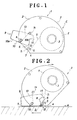
- Fig. 1 shows a side view of an adhesive tape cutting device in a state of stand-by position (nonuse state), wherein a case 1 comprises a self-sustaining table 1a, and a pair of left and right symmetrical wall components 2, each having an arc-shaped wall portion, thereby forming a box-like structure to detachably mount therebetween an adhesive tape roll R.
- One of the wall components 2 is provided with a supporting cylinder 3 on its inner wall for detachably and rotatably supporting the adhesive tape roll R.
- the wall components 2 are respectively provided with a flat bottom 2a, and with a guiding edge portion 4 formed in contiguous to the flat bottom 2a and inclined upward from the flat bottom 2a.
- a temporary fixing member 5 and a delivery guiding member 6 are disposed side by side a temporary fixing member 5 and a delivery guiding member 6 with a slight space formed therebetween.
- This slight space functions as a delivering outlet 7 for an adhesive tape which has been withdrawn or unrolled from the adhesive tape roll R.
- an inner delivered tape portion T1 a portion of the adhesive tape which extends from the adhesive tape roll R to the delivery guide 6 is referred to as an inner delivered tape portion T1
- an outer delivered tape portion T2 a portion of the adhesive tape which extends from the delivery guide 6 to the free end of the adhesive tape
- the temporary fixing member 5 is positioned facing to the adhesive layer-coated side (back side) of the inner delivered tape portion T1, while delivery guiding member 6 is positioned facing to the front side of the outer delivered tape portion T2.
- a shaft 8 At the vicinity of the upper edge portion of the guiding edge portion 4 of the wall components 2 (an edge portion in remote from the flat bottom) is disposed a shaft 8, both ends of which are fixed to the wall components 2. On this shaft 8 is pivotally mounted a movable member 9, whose middle portion being pierced by the shaft 8.
- This movable member 9 is of a box-like shape with the upper portion thereof being opened, and has a flat bottom surface extending from back to forth thereby forming a pressing surface 10, the width thereof being wider than the width of the adhesive tape.
- the pressing surface 10 is formed at least at the portion which located backward from the shaft 8 of the movable member 9. However, in this embodiment, the pressing surface 10 is formed on the entire region of the bottom.
- a forward portion 10a which is located forward from the shaft 8 in the direction of delivering the adhesive tape extends out of the pair of wall components 2, and a rearward portion 10b (essentially, a pressing surface) which is located rearward from the shaft 8 in the direction of delivering the adhesive tape extends to a position near the delivering guide member 6.
- This movable member 9 is mounted in such a manner that when this movable member 9 is rotated to such an extent that the pressing surface 10 becomes in parallel with the guiding edge portion 4, the bottom portion of the pressing surface 10 is slightly exposed out of the bottom of the guiding edge portion 4 as shown in Fig. 2
- an arm member 11 is attached to a portion of the movable member 9, or to the upper portion of the rearward portion 10b.
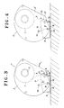
- the tip portion of this arm member 11 is, in this embodiment shown in Fig. 3, adapted to push a middle portion of the inner delivered tape portion T1 and adhere it to the temporary fixing member 5 as the movable member 9 is rotated at an prescribed angle.
- a blade 12 is attached to a portion of the movable member 9 near the rearward portion 10b of the pressing surface portion 10 of the movable member 9 in such a manner that the edge thereof does not extend below beyond the pressing surface portion 10.
- the proximal end portion of the blade 12 is fastened at the middle portion of the rear surface of the movable member 9, and the edge of the blade 12 is slightly spaced apart backward from the rearward portion 10b of the pressing surface portion 10 so as to make it possible to cut the adhesive tape.
- a spring 13 is mounted between the shaft 8 and the shaft 14.
- the shaft 14 also functions as a stopper for restricting the rotation of the movable member 9 to a predetermined range.
- the linear guiding edge portion 4 is pressed onto a surface S of a material to be adhered with the adhesive tape, while grasping the pair of the wall components 2 in hand.
- the movable member 9 is rotated such that the rearward portion 10b of the pressing surface portion 10 moves outward against the elastic force of the spring 13 as shown in Fig. 2, thereby causing the pressing surface portion 10 to come in contact with the surface S, and at the same time causing an free end of the outer delivered tape portion T2, which has been delivered in advance from a space between the temporary fixing member 5 and the delivering guide member 6, to be pressed and adhered on the surface S by the pressure of the pressing surface portion 10.
- the tape T of the tape roll is further unrolled to deliver the outer delivered tape portion T2, which is continuously pressed by the pressing surface 10 thereby adhering a desired length of the adhesive tape on the surface S.
- the wall components 2 is rotated in the direction of "b", while keeping the pressing surface 10 of the movable member 9 pressed onto the surface S, thereby causing the inner delivered tape portion T1 to be bent by the arm member 11 and to adhere it onto the temporary fixing member 5.
- the outer delivered tape portion T2 is pressed and adhered by the pressing surface portion 10, and the inner delivered tape portion T1 is pressed and adhered to the temporary fixing member 5 by the arm member 11, thereby stretching the portion of the adhesive tape extending therebetween.
- the wall components 2 is slightly rotated further, to cause the blade 12 to push and cut this stretched portion of the outer delivered tape portion T2.
- the case 1 After finishing the operations of adhering and cutting the adhesive tape, the case 1 is allowed to be separated from the surface S, thereby causing the movable member 9 to return to its original stand-by position as shown in Fig. 1 due to the elastic force of the spring 13. Since a portion of the inner delivered tape portion T1 is kept adhered onto the temporary fixing member 5, the tip portion of the outer delivered tape portion T2 would not retreat into the wall components 2, but remains as being delivered out of the delivery guiding member 4.
- the rearward portion 10b of the pressing surface 10 of the movable member 9 can take hold of this free tip portion of the outer delivered tape portion T2, and press it onto a surface to be adhered with the adhesive tape.
- any adhesive tape in the form of a roll such as double-faced-tape, gum tape, cloth tape and the like adhesive tape can be used in this invention.
- Fig. 4 explains another embodiment, wherein a temporary fixing member 15 is mounted on an upper portion of a box-like component 2".
- the arm member 11 cause the deformation of a portion of the tape T1, and allow the deformed tape to be adhered onto the temporary fixing member 15, thereby stretching the the tape T1.
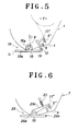
- Fig. 5 explains another embodiment, wherein a movable member 19 is provided with a bracket 19a, and a plate 19b which is rotatably mounted on the shaft 8 is provided with the pressing surface portion 10.
- the movable member 19 further comprises a standing portion 19c standing in an arc-like shape from the rear side of the pressing surface portion 10 so as to avoid an collision with the delivery guiding member (a guide roller) 6' during its rotation, and a tape fixing member 11' extending backward from the standing portion 19c, which is adapted to be contacted with the temporary adhering member 5'.
- Fig. 6 explains further another embodiment, wherein a movable member 29 is modified.
- This movable member 29 comprises a plate 29b having a pressing surface portion 10, and a bracket 29a provided with an arm member 29c extending rearward therefrom, and, at its forward end portion of the arm member 29c, a tape fixing member 11", which is adapted to be contacted with the temporary adhering member 5".
- a coil spring 23 is employed as an energizing means for the movable member 29.
- the direction of advancing the pressing operation by the movable member may be reversed from the above embodiments.
- the pressing surface portion may be of a curved surface, or of a roller.
- the delivery guiding member may guides delivering tape by utilizing a rear corner of a lower part of the movable member.
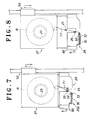
- the adhesive tape cutting device is disposed over a conveying apparatus.
- This apparatus comprises a base member 21 which is adapted to be moved up and down by means a lifting apparatus 50 and sustains a holding member 23 for holding an adhesive tape roll, and a movable member 29 which is mounted in such a manner that the movable member can be lifted up to approach to the base member 21 or descended down to be spaced apart from the base member 21.
- the movable member 29 can be moved up and down in relative to the base member 21 thereby enlarging or shortening the space between the movable member 29 and the adhesive tape roll R.
- This up and down movement 60 of the movable member 29 in relative to the base member 21 can be realized by the following construction.
- a screw shaft is rotatably mounted on the base member 21 in such a manner that the screw shaft can be rotated by means of a motor, and a receiving member such as a nut which is adapted to be engaged with the screw shaft is mounted on the movable member 29 so that the movable member 29 can be moved up and down through the rotation of the screw shaft.
- the movable member 29 may be also connected to a rod of an air cylinder mounted on the base member thereby allowing the movable member to be moved up and down.
- a projected portion 26 which is integrally attached to the movable member 29 functions also as a delivery guiding member and as an arm member.
- the projected portion 26 functioning as an arm member is set at the same level as that of the temporary fixing member 25 which is fixed to the base member 21, and therefore the inner delivered tape portion T1 passing therebetween can be withdrawn without being contacted with the temporary fixing member 25.
- the outer delivered tape portion T2 is pressed and adhered onto the surface of a material to be adhered with the tape by the pressing surface portion 30 which is formed at the lower surface of the forward block 29A of the movable member 29.
- the movable member 29 is lowered in relative to the base member 21 to raise only the base member 21 thus moving the movable member 29 in the direction remote from the adhesive tape roll R.
- the movable member 29 is allowed to raise to approach to the adhesive tape roll R, and the tip portion of the tape resulted from the cutting is allowed to extrude downward from the pressing surface of the movable member 29, thereby preparing for the next adhering operation.
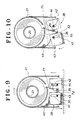
- Figs. 9 and 10 are other embodiments of the tape cutting device according to this invention, wherein the device can be manually operated.
- the movable member 29 is energized to move downward by means of a spring 40.
- This movable member 29 is provided with a pair of elongated pores, i. e. the length of a pore 41 disposed forward is relatively long, and that of a pore 42 disposed backward is relatively short.
- the movable member 29 With the engagement of these elongated ores 41, 42 with these guide pins 43, 44 attached to the case 21, the movable member 29 can be adjusted of its downward action to be worked on the case 21, and is allowed to be moved up and down, or to be inclined forward.
- This device can be operated in the same manner as those of the above embodiments.
- the movable member 29 is capable of being inclined, it has become possible to more easily perform the operation of pressing the tip portion of outer delivered tape portion T2 onto a surface to be adhered.
- the movable member is rotatably mounted in relative to the base member in such a manner that the movable member takes various positions in its movement, i. e. a pressing position wherein the pressing surface portion is in parallel with the guiding edge portion, a cutting position wherein the pressing surface portion is extruded from the guiding edge portion, or a stand-by position wherein the pressing surface is retreated inside the guiding edge. Therefore, it has become possible to easily perform the operation of adhering and cutting by simply effecting displacement of the movable member in relative to the guiding edge.
- the adhesive tape cutting device of this invention is accordingly simple in construction, excellent in reliability and suited for mass production.
- An adhesive tape cutting device rotatably supporting an adhesive tape roll, which is adapted to adhere an adhesive tape of a desired length on a surface of an object, and is capable of reliably and repeatedly delivering the next tip of the tape from the adhesive tape roll for the next adhesion operation.
- the device comprises a delivery guiding member (6) mounted on a base member (1) for guiding the adhesive tape as it is drawn out of the tape roll; a lever (9) movably mounted on the base member; a pressing surface portion (10), which is formed on a bottom portion of the lever (9) for pressing the upper surface of the adhesive tape at the time of adhering the tape; an arm member (11) provided on a portion of the lever (9) for temporarily fixing a delivered portion of the tape on a temporary fixing member (5) mounted on the base member; and a blade (12) mounted on the lever for cuttin a free end portion of the tape. It is possible to perform operations of adhering an cutting by simply displacing the lever (9) in relative to a guiding edge portion (4) formed on the bottom of the base member (1).
Landscapes
- Adhesive Tape Dispensing Devices (AREA)
Applications Claiming Priority (2)
| Application Number | Priority Date | Filing Date | Title |
|---|---|---|---|
| JP6455790 | 1990-06-19 | ||
| JP64557/90U | 1990-06-19 |
Publications (2)
| Publication Number | Publication Date |
|---|---|
| EP0462577A2 true EP0462577A2 (de) | 1991-12-27 |
| EP0462577A3 EP0462577A3 (en) | 1992-02-26 |
Family
ID=13261653
Family Applications (1)
| Application Number | Title | Priority Date | Filing Date |
|---|---|---|---|
| EP19910109993 Withdrawn EP0462577A3 (en) | 1990-06-19 | 1991-06-18 | Adhesive tape cutting device |
Country Status (3)
| Country | Link |
|---|---|
| US (1) | US5181983A (de) |
| EP (1) | EP0462577A3 (de) |
| CA (1) | CA2044995A1 (de) |
Cited By (1)
| Publication number | Priority date | Publication date | Assignee | Title |
|---|---|---|---|---|
| EP1028078A3 (de) * | 1999-01-16 | 2002-03-13 | Stahl, Marc-Anton | Handabrollgerät für flexibles Rollenmaterial |
Families Citing this family (12)
| Publication number | Priority date | Publication date | Assignee | Title |
|---|---|---|---|---|
| US5861080A (en) * | 1997-03-25 | 1999-01-19 | Yang; Xinnong | Tape dispenser |
| USD407438S (en) | 1997-12-31 | 1999-03-30 | Henkel Kgaa | Holder with correcting tape |
| USD432575S (en) * | 1999-04-07 | 2000-10-24 | Ray Technology Group B.V. | Tape dispenser |
| DE19936130C2 (de) * | 1999-07-31 | 2003-06-12 | Vulkan Technic Maschinen Konst | Bandabroller, insbesondere Klebebandabroller |
| ITCR990011A1 (it) * | 1999-11-08 | 2001-05-08 | Fernando Peggion | Dispositivo dispensatore ed applicatore automatico di nastro adesivo in rotolo |
| US7017639B2 (en) * | 2002-11-09 | 2006-03-28 | Henkel Consumer Adhesives, Inc. | Blade protector for tape dispenser |
| US7195048B2 (en) * | 2003-06-04 | 2007-03-27 | Henkel Consumer Adhesives, Inc. | Adhesive film dispenser |
| US7178575B2 (en) * | 2004-11-05 | 2007-02-20 | Hsiu-Man Yu Chen | Label maker |
| US7380693B2 (en) * | 2006-05-04 | 2008-06-03 | Pei-Lin Huang | Desktop tape dispenser |
| US20120305198A1 (en) * | 2010-02-18 | 2012-12-06 | Harrison Huang | Adhesive tape dispenser |
| US8479794B2 (en) * | 2011-06-23 | 2013-07-09 | Shurtech Brands, Llc | Locking tape dispenser |
| US8813806B2 (en) | 2011-06-23 | 2014-08-26 | Shurtech Brands, Llc | Locking tape dispenser |
Family Cites Families (10)
| Publication number | Priority date | Publication date | Assignee | Title |
|---|---|---|---|---|
| US3027292A (en) * | 1960-04-13 | 1962-03-27 | Rothenberger Hansjorg | Manual apparatus for applying an adhesive tape over an edge |
| CH406897A (de) * | 1964-02-20 | 1966-01-31 | Vogel Erwin | Klebband-Spender |
| US3306806A (en) * | 1964-07-20 | 1967-02-28 | Edward S Seropian | Tape dispenser with coordinated dispensing, sealing and cutting mechanism |
| FR1595402A (de) * | 1968-12-19 | 1970-06-08 | ||
| DE2321240A1 (de) * | 1973-04-26 | 1974-11-21 | Duron Ind Ltd | Bandabroller |
| CH631675A5 (en) * | 1979-10-29 | 1982-08-31 | Sakae Urushizaki | Device for applying an adhesive strip |
| US4253905A (en) * | 1980-01-07 | 1981-03-03 | Regan James L | Tape dispenser |
| JPS56140545U (de) * | 1980-03-19 | 1981-10-23 | ||
| US4608116A (en) * | 1985-06-20 | 1986-08-26 | Keith Braselton | Baseboard edge taping tool |
| SE449605B (sv) * | 1985-09-13 | 1987-05-11 | Per Ingemar Nordstrom | Hallare for klisterremsor |
-
1991
- 1991-06-18 EP EP19910109993 patent/EP0462577A3/en not_active Withdrawn
- 1991-06-19 CA CA 2044995 patent/CA2044995A1/en not_active Abandoned
- 1991-06-19 US US07/717,493 patent/US5181983A/en not_active Expired - Fee Related
Cited By (1)
| Publication number | Priority date | Publication date | Assignee | Title |
|---|---|---|---|---|
| EP1028078A3 (de) * | 1999-01-16 | 2002-03-13 | Stahl, Marc-Anton | Handabrollgerät für flexibles Rollenmaterial |
Also Published As
| Publication number | Publication date |
|---|---|
| US5181983A (en) | 1993-01-26 |
| CA2044995A1 (en) | 1991-12-20 |
| EP0462577A3 (en) | 1992-02-26 |
Similar Documents
| Publication | Publication Date | Title |
|---|---|---|
| US5181983A (en) | Adhesive tape cutting device | |
| US5468321A (en) | Apparatus and method for joining two webs together | |
| US5173140A (en) | Tape applying device and method for applying tape | |
| JPH07285521A (ja) | 粘着テープ貼着方法及びその装置 | |
| JPS5845042A (ja) | 成形ドラムへのゴムシ−ト貼付方法および装置 | |
| US3472724A (en) | Apparatus for severing tape | |
| EP0345606A2 (de) | Auftragevorrichtung für Acrylschaumstreifen | |
| DE10201368C1 (de) | Schere zum Schneiden von Bandmaterial | |
| US3970507A (en) | Tape dispenser and method of dispensing tape | |
| AT398722B (de) | Abstützeinrichtung für schnittgut auf einem schnittgutwagen einer aufschnittschneidemaschine | |
| EP0335270A1 (de) | Vorrichtung zum sequentiellen Schweissen von endlosen, thermoplastischen Platten entlang festgelegter Konturen und zum Abtrennen von Artikeln aus solchen Platten | |
| US4052240A (en) | Taping device and method of taping | |
| US4212217A (en) | Web dispenser | |
| JP2760930B2 (ja) | シールテープ自動貼付け装置 | |
| US5192385A (en) | Method for the application of lengths of tape to a surface | |
| JP3086824B2 (ja) | 粘着テープ切断装置 | |
| US3613239A (en) | Cutter for floor covering such as linoleum and the like | |
| JPS6344653B2 (de) | ||
| US5304275A (en) | Applying a reinforcement film to sheets | |
| JP5271684B2 (ja) | 粘着テープの供給装置 | |
| JPH1016923A (ja) | 封緘機 | |
| JP2562323B2 (ja) | テ−プ貼着装置の貼着ヘッド | |
| SE457070B (sv) | Saett och anordning foer framstaellning av dubbelvikta etiketter | |
| JPS5935480Y2 (ja) | 接着テ−プのカッタ−装置 | |
| JPH06345313A (ja) | シールテープ自動貼付け装置 |
Legal Events
| Date | Code | Title | Description |
|---|---|---|---|
| PUAI | Public reference made under article 153(3) epc to a published international application that has entered the european phase |
Free format text: ORIGINAL CODE: 0009012 |
|
| AK | Designated contracting states |
Kind code of ref document: A2 Designated state(s): DE FR GB |
|
| PUAL | Search report despatched |
Free format text: ORIGINAL CODE: 0009013 |
|
| AK | Designated contracting states |
Kind code of ref document: A3 Designated state(s): DE FR GB |
|
| 17P | Request for examination filed |
Effective date: 19920727 |
|
| 17Q | First examination report despatched |
Effective date: 19931129 |
|
| STAA | Information on the status of an ep patent application or granted ep patent |
Free format text: STATUS: THE APPLICATION IS DEEMED TO BE WITHDRAWN |
|
| 18D | Application deemed to be withdrawn |
Effective date: 19950102 |