EP0460484A2 - Verschlussvorrichtung an einer Wärmebehandlungsanlage - Google Patents
Verschlussvorrichtung an einer Wärmebehandlungsanlage Download PDFInfo
- Publication number
- EP0460484A2 EP0460484A2 EP91108540A EP91108540A EP0460484A2 EP 0460484 A2 EP0460484 A2 EP 0460484A2 EP 91108540 A EP91108540 A EP 91108540A EP 91108540 A EP91108540 A EP 91108540A EP 0460484 A2 EP0460484 A2 EP 0460484A2
- Authority
- EP
- European Patent Office
- Prior art keywords
- recipient
- door
- lid
- boiler
- closure device
- Prior art date
- Legal status (The legal status is an assumption and is not a legal conclusion. Google has not performed a legal analysis and makes no representation as to the accuracy of the status listed.)
- Withdrawn
Links
Images

Classifications
-
- C—CHEMISTRY; METALLURGY
- C21—METALLURGY OF IRON
- C21D—MODIFYING THE PHYSICAL STRUCTURE OF FERROUS METALS; GENERAL DEVICES FOR HEAT TREATMENT OF FERROUS OR NON-FERROUS METALS OR ALLOYS; MAKING METAL MALLEABLE, e.g. BY DECARBURISATION OR TEMPERING
- C21D1/00—General methods or devices for heat treatment, e.g. annealing, hardening, quenching or tempering
- C21D1/74—Methods of treatment in inert gas, controlled atmosphere, vacuum or pulverulent material
- C21D1/773—Methods of treatment in inert gas, controlled atmosphere, vacuum or pulverulent material under reduced pressure or vacuum
-
- C—CHEMISTRY; METALLURGY
- C21—METALLURGY OF IRON
- C21D—MODIFYING THE PHYSICAL STRUCTURE OF FERROUS METALS; GENERAL DEVICES FOR HEAT TREATMENT OF FERROUS OR NON-FERROUS METALS OR ALLOYS; MAKING METAL MALLEABLE, e.g. BY DECARBURISATION OR TEMPERING
- C21D9/00—Heat treatment, e.g. annealing, hardening, quenching or tempering, adapted for particular articles; Furnaces therefor
- C21D9/0006—Details, accessories not peculiar to any of the following furnaces
-
- F—MECHANICAL ENGINEERING; LIGHTING; HEATING; WEAPONS; BLASTING
- F27—FURNACES; KILNS; OVENS; RETORTS
- F27B—FURNACES, KILNS, OVENS OR RETORTS IN GENERAL; OPEN SINTERING OR LIKE APPARATUS
- F27B5/00—Muffle furnaces; Retort furnaces; Other furnaces in which the charge is held completely isolated
- F27B5/04—Muffle furnaces; Retort furnaces; Other furnaces in which the charge is held completely isolated adapted for treating the charge in vacuum or special atmosphere
-
- F—MECHANICAL ENGINEERING; LIGHTING; HEATING; WEAPONS; BLASTING
- F27—FURNACES; KILNS; OVENS; RETORTS
- F27D—DETAILS OR ACCESSORIES OF FURNACES, KILNS, OVENS OR RETORTS, IN SO FAR AS THEY ARE OF KINDS OCCURRING IN MORE THAN ONE KIND OF FURNACE
- F27D1/00—Casings; Linings; Walls; Roofs
- F27D1/18—Door frames; Doors, lids or removable covers
- F27D1/1858—Doors
Definitions
- the invention relates to a closure device on a heat treatment system, which consists of a boiler designed for vacuum and high-pressure operation, wherein a recipient for receiving a batch is located within the boiler, the recipient is surrounded by heating and thermal insulation and the boiler and the Thermal insulation with a door and the recipient can be closed with a lid.
- Such systems are used, for example, for sintering materials.
- the basic principle of a sintering plant for the heat treatment of batches under vacuum with subsequent hot isostatic aftertreatment is described, for example, in DE PS-30 14 691, DE OS-36 21 996 and in US-PS 43 98 702.
- a boiler designed for vacuum and high pressure operation there is a recipient which encloses the usable space. This recipient is surrounded by a heater. Insulation is installed between the heating and the boiler wall for thermal shielding.
- lids or doors are provided on the end face and on the end faces of the thermal insulation and the boiler.
- the treated batch After the heat treatment in such a plant is completed, the treated batch must be cooled. For economic and procedural reasons, rapid and effective cooling is necessary to keep cycle times as short as possible. In the higher pressure range, cooling is mainly done by convection. A faster cooling by gas circulation can be achieved by opening the recipient lid after the treatment, so that a large conductivity is available. During this process, however, good thermal insulation should remain between the recipient and the boiler wall, since this must be kept at a low temperature, inter alia, for reasons of material strength. Therefore, the aim should be that the isolation door remains closed during this process step.
- the parts to be sintered are pressed with binders, such as paraffin or polyethylene glycol or also thermoplastics, in order to give the parts a sufficiently high basic strength, it is necessary to drive out these binders before the sintering process.
- the recipient lid must be closed in order to prevent binder vapors from entering the heating zone and thus the thermal insulation and thus impairing their effectiveness.
- the recipient lid must be open when the pressurized gas inlet and pressurized gas are operated. This is necessary for safety reasons, otherwise the recipient would be compressed by the pressure. In addition, as already mentioned above, this is conducive to rapid cooling.
- a closure device for heat treatment furnaces which serves to close the outer boiler, the thermal insulation and the recipient.
- This device has the disadvantage that the boiler lid can only be opened together with the insulation door and the recipient lid. It is therefore very difficult or even impossible to control the position of the closures.
- Another disadvantage is that the thermal expansions occurring in heat treatment processes can only be absorbed with difficulty.
- the present invention has for its object to develop a closure device on a heat treatment system, through which the above-mentioned disadvantages are avoided, in particular when the boiler and insulation door is closed, the recipient lid can be reproducibly opened and closed.
- the recipient lid should always be in the safe open position if the locking mechanism fails or if there is a power failure. Control of the position of the recipient lid must be possible from the outside. Thermal expansion should be compensated for by the device according to the invention without loss of functionality.
- the construction according to the invention makes it possible to design the locking device in such a way that in the event of failure of the closing mechanism or in the event of a power failure, the recipient lid is always in the safe, open position and the isolation door is in the safe, closed position. The open state of the recipient lid can be checked from the outside.
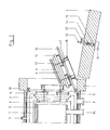
- FIG. 1 shows a section of the arrangement according to the invention in the closed state and FIG. 2 shows a corresponding section for the open state.
- the recipient 5 Inside the boiler 1, which can be closed with the boiler door 2, there is the recipient 5 with the recipient lid 6.
- the recipient 5 is surrounded by a heater 7.
- the thermal insulation 3 is attached between the heater 7 and the boiler 1. It is closed by the isolation door 4.
- the flanges 8 and 9 are used to connect devices for evacuating or for generating a high pressure. In the case of a sintering process, the binder vapors are led from the recipient into an external condenser via the steam line 9a.
- a pivotable frame 10 On the wall of the boiler 1, a pivotable frame 10 is attached, which carries the insulation door 4. This is pressed against the thermal insulation 3 by spring elements 11, which are also fastened to the frame 10.
- the spring elements 17 serve to open the recipient lid 6.
- the spring element 14 has the function of compensating for the thermal expansion of the recipient 5 and at the same time producing the counterforce to the spring elements 17 in order to fix the position of the recipient lid 6.
- the frame 10 After loading the recipient, the frame 10 is brought into the closed position with the spring elements 11 and fixed with the locking device 19.
- the insulation door 4 is closed while the boiler door 2 and the recipient lid 6 are still open after this step.
- the open boiler door 2 can be used to check whether the insulation door 4 has been sealed. Then the boiler door 2 is closed.
- mechanical pressure is applied with the aid of the drive 16 via the drive rod 15, the spring 14 and the plunger 13 exerted on the cross connection 18, the plunger 13 comes into contact with the cross connection 18, the spring elements 17 are pressed together, and the recipient cover 6 is moved into the closed position.
- the drive rod 15 is retracted by the drive 16.
- the spring elements 17 can relax via the cross connection 18, the plunger 13 and the spring element 14, as a result of which the recipient cover 6 is opened.
- the plunger 13 has no non-positive connection with the spring element 14, it can only move back if it is pushed back by the spring elements 17 via the cross connection 18. Since this process is associated with the opening of the recipient lid 6, the movement of the plunger 13 gives the possibility of checking the opening state of the recipient lid 6 with the aid of the switch 20, which signals the respective position of the recipient lid 6.
Landscapes
- Engineering & Computer Science (AREA)
- Chemical & Material Sciences (AREA)
- Mechanical Engineering (AREA)
- Materials Engineering (AREA)
- Crystallography & Structural Chemistry (AREA)
- Thermal Sciences (AREA)
- Physics & Mathematics (AREA)
- Metallurgy (AREA)
- Organic Chemistry (AREA)
- General Engineering & Computer Science (AREA)
- Furnace Housings, Linings, Walls, And Ceilings (AREA)
- Furnace Details (AREA)
- Pressure Vessels And Lids Thereof (AREA)
- Muffle Furnaces And Rotary Kilns (AREA)
Abstract
Description
- Die Erfindung betrifft eine Verschlußvorrichtung an einer Wärmebehandlungsanlage, welche aus einem für Vakuum- und Hochdruckbetrieb ausgelegten Kessel besteht, wobei sich innerhalb des Kessels ein Rezipient zur Aufnahme einer Charge befindet, der Rezipient von einer Heizung und einer thermischen Isolation umgeben ist und der Kessel und die thermische Isolation mit einer Tür und der Rezipient mit einem Deckel verschließbar sind.
- Solche Anlagen werden zum Beispiel zum Sintern von Werkstoffen eingesetzt. Das Grundprinzip einer Sinteranlage zum Wärmebehandeln von Chargen unter Vakuum mit anschließendem heißisostatischem Nachbehandeln ist zum Beispiel in den DE PS-30 14 691, DE OS-36 21 996 und in der US-PS 43 98 702 beschrieben. In einem für Vakuum- und Hochdruckbetrieb ausgelegten Kessel befindet sich ein Rezipient, welcher den Nutzraum umschließt. Dieser Rezipient ist von einer Heizung umgeben. Zur thermischen Abschirmung ist zwischen Heizung und Kesselwand eine Isolation angebracht. Zum Be- und Entladen des Rezipienten sind an dessen Stirnseite und an den Stirnseiten der thermischen Isolation und des Kessels Deckel bzw. Türen vorgesehen.
- Nachdem die Wärmebehandlung in einer solchen Anlage abgeschlossen ist, muß die behandelte Charge abgekühlt werden. Aus wirtschaftlichen und verfahrenstechnischen Gründen ist eine schnelle und effektive Abkühlung notwendig, um die Zykluszeiten möglichst kurz zu halten. Die Kühlung erfolgt im höheren Druckbereich hauptsächlich durch Konvektion. Eine schnellere Abkühlung durch Gasumwälzung kann erreicht werden, indem nach der Behandlung der Rezipientendeckel geöffnet wird, damit ein großer Leitwert zur Verfügung steht. Während dieses Vorganges sollte aber eine gute thermische Isolation zwischen Rezipient und Kesselwand bestehen bleiben, da diese unter anderem aus Gründen der Materialfestigkeit auf niedriger Temperatur gehalten werden muß. Daher sollte angestrebt werden, daß die Isolationstür während dieses Verfahrensschrittes geschlossen bleibt.
- Da bei vielen Sinterprozessen die zu sinterenden Teile mit Bindemitteln, wie Paraffin oder Polyäthylenglykol oder auch Thermoplasten verpreßt werden, um den Teilen eine genügend hohe Grundfestigkeit zu geben, ist es notwendig, diese Bindemittel vor dem Sinterprozeß auszutreiben. Zu diesem Zweck muß der Rezipientendeckel geschlossen sein, um zu verhindern, daß Bindemitteldämpfe in die Heizzone und damit in die thermische Isolation gelangen und so deren Wirkung beeinträchtigen. Zum Absaugen der Bindemitteldämpfe ist eine separate Dampfleitung zwischen dem Rezipienten und einem externen Kondensator vorhanden.
- Bei Druckgaseinlaß und bei Druckgasbetrieb muß der Rezipientendeckel unbedingt offen sein. Dies ist aus Sicherheitsgründen erforderlich, da sonst der Rezipient durch den Druck zusammengedrückt würde. Außerdem kommt dies, wie oben schon erwähnt, einer schnellen Kühlung entgegen.
- Aus dem DE GM 87 14 544 ist eine Verschlußvorrichtung für Wärmebehandlungsöfen bekannt, welche zum Verschließen des äußeren Kessels, der thermischen Isolation und des Rezipienten dient. Diese Vorrichtung hat den Nachteil, daß der Kesseldeckel nur gemeinsam mit der Isolationstür und dem Rezipientendeckel geöffnet werden kann. Somit ist eine Kontrolle über die Position der Verschlüsse sehr schwer oder überhaupt nicht durchführbar. Ein weiterr Nachteil besteht darin, daß die bei Wärmebehandlungsprozessen auftretenden Wärmedehnungen nur schlecht aufgefangen werden können.
- Der vorliegenden Erfindung liegt die Aufgabe zugrunde, eine Verschlußvorrichtung an einer Wärmebehandlungsanlage zu entwickeln, durch welche die obengenannten Nachteile vermieden werden, insbesondere soll bei geschlossener Kessel- und Isolationstür der Rezipientendeckel reproduzierbar geöffnet und geschlossen werden können. Aus Sicherheitsgründen soll der Rezipientendeckel bei Ausfall des Schließmechanismus oder bei Stromausfall immer in der sicheren offenen Position sein. Eine Kontrolle über die Position des Rezipientendeckels muß von außen her möglich sein. Wärmedehnungen sollen durch die erfindungsgemäße Einrichtung ohne Einbuße der Funktionsfähigkeit kompensiert werden.
- Die Aufgabe wird gelöst durch den kennzeichnenden Teil des ersten Patentanspruches. Die Ansprüche 2 bis 8 stellen weitere Ausgestaltungen der Erfindung dar.
- Durch die erfindungsgemäße Konstruktion wird es möglich, die Verschlußvorrichtung so zu gestalten, daß bei Ausfall des Schließmechanismus oder bei Stromausfall der Rezipientendeckel immer in der sicheren, offenen Position und die Isolationstür in der sicheren, geschlossenen Position ist. Der geöffnete Zustand des Rezipientendeckels kann von außen her kontrolliert werden.
- Fig. 1 zeigt einen Schnitt der erfindungsgemäßen Anordnung im geschlossenen Zustand und Fig.2 einen entsprechenden Schnitt für den geöffneten Zustand.
- Innerhalb des Kessels 1, welcher mit der Kesseltür 2 verschließbar ist, befindet sich der Rezipient 5 mit dem Rezipientendeckel 6. Der Rezipient 5 wird von einer Heizung 7 umgeben. Zur Vermeidung der Wärmeübertragung an den Kessel 1 ist zwischen der Heizung 7 und dem Kessel 1 die thermische Isolation 3 angebracht. Sie wird durch die Isolationstür 4 abgeschlossen. Die Flansche 8 und 9 dienen zum Anschluß von Einrichtungen zum Evakuieren bzw. zum Erzeugen eines Hochdruckes. Über die Dampfleitung 9a werden im Falle eines Sinterprozesses die Bindemitteldämpfe aus dem Rezipienten in einen externen Kondensator geführt.
- An der Wand des Kessels 1 ist ein schwenkbares Gestell 10 befestigt, welches die Isolationstür 4 trägt. Diese wird durch Federelemente 11, welche ebenfalls an dem Gestell 10 befestigt sind, an die thermische Isolation 3 gedrückt. Eine Verschiebevorrichtung 12, welche ebenfalls an dem Gestell 10 befestigt ist, trägt den Rezipientendeckel 6. Diese Verschiebevorrichtung 12 steht mittels der Querverbindung 18, über den Stößel 13, das Federelement 14 und die Antriebsstange 15 mit dem Antrieb 16 in Kontakt. Dabei besteht keine kraftschlüssige Verbindung zwischen dem Stößel 13 und der Querverbindung 18 einerseits und dem Stößel 13 und dem Federelement 14 andererseits. Die Federelemente 17 dienen zum Öffnen des Rezipientendeckels 6. Das Federelement 14 hat die Funktion, die thermische Ausdehnung des Rezipienten 5 zu kompensieren und gleichzeitig die Gegenkraft zu den Federelementen 17 herzustellen, um die Stellung des Rezipientendeckels 6 zu fixieren.
- Nach dem Beschicken des Rezipienten wird das Gestell 10 mit den Federelementen 11 in die Schließposition gebracht und mit der Arretiervorrichtung 19 festgesetzt. Dabei wird die Isolationstür 4 geschlossen, während die Kesseltür 2 und der Rezipientendeckel 6 nach diesem Schritt noch geöffnet sind. Durch die offene Kesseltür 2 kann kontrolliert werden, ob die Isolationstür 4 dicht abgeschlossen hat. Danach wird die Kesseltür 2 geschlossen. Zum Schließen des Rezipientendeckels 6 wird mit Hilfe des Antriebs 16 über die Antriebsstange 15, die Feder 14 und den Stößel 13 mechanischer Druck auf die Querverbindung 18 ausgeübt, der Stößel 13 kommt mit der Querverbindung 18 in Berührung, die Federelemente 17 werden zusammengedrückt, und der Rezipientendeckel 6 wird in die Schließposition gefahren.
- Zum Öffnen des Rezipientendeckels 6 wird die Antriebsstange 15 durch den Antrieb 16 zurückgefahren. Dadurch können sich die Federelemente 17 über die Querverbindung 18, den Stößel 13 und das Federelement 14 entspannen, wodurch der Rezipientendeckel 6 geöffnet wird.
- Dadurch, daß der Stößel 13 keine kraftschlüssige Verbindung mit den Federelement 14 hat, kann er sich nur dann zurückbewegen, wenn er durch die Federelemente 17 über die Querverbindung 18 zurückgedrückt wird. Da dieser Vorgang mit einem Öffnen des Rezipientendeckels 6 verbunden ist, ergibt sich durch die Bewegung des Stößels 13 eine Möglichkeit, den Öffnungszustand des Rezipientendeckels 6 mit Hilfe des Schalters 20, welcher die jeweilige Lage des Rezipientendeckels 6 signalisiert, zu kontrollieren.
Claims (8)
- Verschlußvorrichtung an einer Wärmebehandslungsanlage, welche aus einem für Vakuum- und Hochdruckbetrieb ausgelegten Kessel (1) besteht, wobei sich innerhalb des Kessels ein Rezipient (5) zur Aufnahme einer zu bahandelnden Charge befindet, der Rezipient (5) von einer Heizung (7) und einer thermischen Isolation (3) umgeben ist und der Kessel (1) mit einer druckfesten Tür (2) verschließbar ist, die thermische Isolation (3) stirnseitig eine bewegliche Isolationstür (4) aufweist und der Rezipient (5) stirnseitig mit einer beweglichen Deckeltür (6) verschließbar ist, dadurch gekennzeichnet, daß die Isolationstür (4) und der Rezipientendekkel (6) in einem gemeinsamen Gestell (10), unabhängig von der Kesseltür (2), und in voneinander unabhängigen Aufnahmevorrichtungen an diesem Gestell (10) beweglich befestigt sind.
- Verschlußvorrichtung nach Anspruch 1, dadurch gekennzeichnet, daß die Aufnahme der Isolationstür (4) am Gestell (10) durch Federelement (11) geschieht, welche die Isolationstür (4) ohne äußere Betätigung immer in der geschlossenen Position halten.
- Verschlußvorrichtung nach Anspruch 1 oder 2, dadurch gekennzeichnetm daß die Aufnahme des Rezipientendeckels (6) am Gestell (10) durch Federelemente (17) geschieht, welche den Rezipientendeckel (6) ohne äußere Betätigung immer in der geöffneten Position halten.
- Verschlußvorrichtung nach Anspruch 3, dadurch gekennzeichnet, daß der Rezipientendeckel (6) von einer Position außerhalb der Kesseltür (2) her gegen den Druck der Federelemente (17) verschließbar ist.
- Verschlußvorrichtung nach Anspruch 3, dadurch gekennzeichnet, daß der Rezipientendeckel (6) von einer Position außerhalb der Kesseltür (2) her ohne kraftschlüssige Verbindung geöffnet werden kann.
- Verschlußvorrichtung nach Anspruch 5, dadurch gekennzeichnet, daß zwischen Rezipientendeckel (6) und einem außerhalb der Kesseltür (2) angeordneten Antrieb (16) sich ein Stößel (13) befindet, welcher keine kraftschlüssige Verbindung mit dem Antrieb (16) hat und nur dann in Richtung des Antriebs (16) bewegt wird, wenn sich der Rezipientendeckel (6) öffnet.
- Verschlußvorrichtung nach Anspruch 6, dadurch gekennzeichnet, daß zur Anzeige des Öffnungszustandes des Rezipientendeckels (6) ein Schalter (20) vorhanden ist, welcher von dem Stößel (13) betätigt wird.
- Verschlußvorrichtung nach einem der vorhergehenden Ansprüche, dadurch gekennzeichnet, daß zwischen Rezipientendeckel (6) und dem äußeren Antrieb (16) ein Federelement (14) zum Ausgleich der thermischen Ausdehnung des Rezipienten (5) angeordnet ist.
Applications Claiming Priority (2)
| Application Number | Priority Date | Filing Date | Title |
|---|---|---|---|
| DE4017942 | 1990-06-05 | ||
| DE4017942 | 1990-06-05 |
Publications (2)
| Publication Number | Publication Date |
|---|---|
| EP0460484A2 true EP0460484A2 (de) | 1991-12-11 |
| EP0460484A3 EP0460484A3 (en) | 1992-02-26 |
Family
ID=6407790
Family Applications (1)
| Application Number | Title | Priority Date | Filing Date |
|---|---|---|---|
| EP19910108540 Withdrawn EP0460484A3 (en) | 1990-06-05 | 1991-05-24 | Closure device for a heat treatment installation |
Country Status (3)
| Country | Link |
|---|---|
| US (1) | US5193998A (de) |
| EP (1) | EP0460484A3 (de) |
| JP (1) | JPH04227470A (de) |
Cited By (4)
| Publication number | Priority date | Publication date | Assignee | Title |
|---|---|---|---|---|
| US5267259A (en) * | 1991-07-30 | 1993-11-30 | Abb Patent Gmbh | Induction crucible furnace with sonically uncoupled accessible furnace platform |
| EP2224020A1 (de) * | 2009-02-12 | 2010-09-01 | Seco/Warwick S.A. | Retortenofen für thermische und/oder thermochemische Behandlungsverfahren |
| CN115448721A (zh) * | 2022-09-07 | 2022-12-09 | 重庆镪正科技有限公司 | 一种浸铜碳滑板材料及其浸铜碳滑板的制备方法 |
| US11971216B1 (en) | 2021-12-23 | 2024-04-30 | Rolls-Royce High Temperature Composites, Inc. | Retort with loading window |
Families Citing this family (26)
| Publication number | Priority date | Publication date | Assignee | Title |
|---|---|---|---|---|
| US5256061A (en) * | 1992-03-02 | 1993-10-26 | Cress Steven B | Method and apparatus for vacuum furnace with self sealing expansion door members |
| US5302120A (en) * | 1992-06-15 | 1994-04-12 | Semitool, Inc. | Door assembly for semiconductor processor |
| US5449289A (en) * | 1992-06-15 | 1995-09-12 | Semitool, Inc. | Semiconductor processor opening and closure construction |
| US5285736A (en) * | 1992-12-18 | 1994-02-15 | Joy Technologies Inc. | Pressure relief apparatus for a vessel |
| DE9301293U1 (de) * | 1993-01-30 | 1993-03-11 | Ipsen Industries International Gmbh, 4190 Kleve | Halterung zur partiellen Wärmebehandlung von Werkzeugen |
| US5803021A (en) * | 1994-10-11 | 1998-09-08 | Combustion Engineering, Inc. | Boiler access door construction |
| US6017215A (en) * | 1996-10-15 | 2000-01-25 | Reliability Inc. | Expandable panel for environmentally controllable chamber |
| US6609908B2 (en) * | 2001-11-13 | 2003-08-26 | Ets Schaefer Corporation | Replaceable heater cover |
| KR100848624B1 (ko) * | 2001-12-26 | 2008-07-28 | 주식회사 포스코 | 탈가스 베셀 진공리크 방지를 위한 센터링 장치 |
| JP4855785B2 (ja) * | 2006-01-20 | 2012-01-18 | 日本電産シンポ株式会社 | 陶芸窯の扉の構造 |
| US8523563B1 (en) * | 2008-01-07 | 2013-09-03 | Anthony Nardella | Kiln brick protective collar |
| US10023954B2 (en) * | 2011-09-15 | 2018-07-17 | Applied Materials, Inc. | Slit valve apparatus, systems, and methods |
| JP6521437B2 (ja) * | 2015-04-10 | 2019-05-29 | 日本電産シンポ株式会社 | 焼成炉 |
| CN105737609A (zh) * | 2016-04-18 | 2016-07-06 | 兰州兰石重型装备股份有限公司 | 一种炉门辅助工装及其使用方法 |
| JP6863158B2 (ja) * | 2017-07-24 | 2021-04-21 | 日本製鉄株式会社 | 管端蓋及びそれを用いた鋼管の製造方法 |
| CN113261080B (zh) * | 2019-02-20 | 2024-11-26 | 株式会社国际电气 | 基板处理装置、炉口封闭单元及半导体器件的制造方法 |
| USD907190S1 (en) | 2019-04-24 | 2021-01-05 | Anthony Nardella | Kiln brick protective collar with apertures |
| USD892297S1 (en) | 2019-04-24 | 2020-08-04 | Anthony Nardella | Kiln brick protective collar |
| USD910831S1 (en) | 2019-04-24 | 2021-02-16 | Anthony Nardella | Kiln brick protective collar with adjustable tabs |
| USD910832S1 (en) | 2019-04-24 | 2021-02-16 | Anthony Nardella | Kiln brick protective collar with tabs |
| USD889628S1 (en) | 2019-04-24 | 2020-07-07 | Anthony Nardella | Kiln brick protective collar with adjustable tab |
| USD889629S1 (en) | 2019-04-24 | 2020-07-07 | Anthony Nardella | Kiln brick protective collar |
| CN111021872B (zh) * | 2019-12-31 | 2020-09-15 | 株洲瑞德尔冶金设备制造有限公司 | 一种烧结炉炉门控制装置 |
| USD951425S1 (en) | 2020-01-22 | 2022-05-10 | Anthony Nardella | Hinged kiln brick protective collar |
| US11466934B2 (en) | 2020-01-22 | 2022-10-11 | Anthony Nardella | Hinged kiln brick protective collar |
| USD934408S1 (en) | 2020-01-22 | 2021-10-26 | Anthony Nardella | Hinged kiln brick protective collar |
Family Cites Families (7)
| Publication number | Priority date | Publication date | Assignee | Title |
|---|---|---|---|---|
| USRE18668E (en) * | 1932-11-29 | Heat treating furnace | ||
| US1432591A (en) * | 1920-07-07 | 1922-10-17 | Addison B Carll | Dome cover for tank cars |
| US2262960A (en) * | 1940-08-02 | 1941-11-18 | Philip C Osterman | Retort and support therefor |
| DE874146C (de) * | 1943-05-14 | 1953-04-20 | Ofu Ofenbau Union G M B H | Fahrbarer Gewoelbedeckel fuer OEfen |
| US3055321A (en) * | 1958-11-24 | 1962-09-25 | Babcock & Wilcox Co | Access door |
| DE3621996A1 (de) * | 1986-07-01 | 1988-01-14 | Pfeiffer Vakuumtechnik | Anlage zum waermebehandeln von werkstoffen im vakuum und unter druck |
| DE8714544U1 (de) * | 1987-10-31 | 1987-12-23 | Degussa Ag, 6000 Frankfurt | Ofenverschluß für Industrieöfen |
-
1991
- 1991-05-07 JP JP3101429A patent/JPH04227470A/ja active Pending
- 1991-05-24 EP EP19910108540 patent/EP0460484A3/de not_active Withdrawn
- 1991-06-05 US US07/710,672 patent/US5193998A/en not_active Expired - Fee Related
Cited By (6)
| Publication number | Priority date | Publication date | Assignee | Title |
|---|---|---|---|---|
| US5267259A (en) * | 1991-07-30 | 1993-11-30 | Abb Patent Gmbh | Induction crucible furnace with sonically uncoupled accessible furnace platform |
| EP2224020A1 (de) * | 2009-02-12 | 2010-09-01 | Seco/Warwick S.A. | Retortenofen für thermische und/oder thermochemische Behandlungsverfahren |
| US9115414B2 (en) | 2009-02-12 | 2015-08-25 | Seco/Warwick S.A. | Retort furnace for heat and/or thermochemical treatment |
| US11971216B1 (en) | 2021-12-23 | 2024-04-30 | Rolls-Royce High Temperature Composites, Inc. | Retort with loading window |
| CN115448721A (zh) * | 2022-09-07 | 2022-12-09 | 重庆镪正科技有限公司 | 一种浸铜碳滑板材料及其浸铜碳滑板的制备方法 |
| CN115448721B (zh) * | 2022-09-07 | 2023-11-17 | 重庆镪正科技有限公司 | 一种浸铜碳滑板的制备方法 |
Also Published As
| Publication number | Publication date |
|---|---|
| US5193998A (en) | 1993-03-16 |
| EP0460484A3 (en) | 1992-02-26 |
| JPH04227470A (ja) | 1992-08-17 |
Similar Documents
| Publication | Publication Date | Title |
|---|---|---|
| CH680522A5 (de) | ||
| DE2430972A1 (de) | Vorrichtung zur herstellung von gegenstaenden aus teilchenmaterial | |
| EP0452702B1 (de) | Feststellvorrichtung für eine Linearbewegungseinheit | |
| AT394673B (de) | Anlage zum waermebehandeln von werkstoffen im vakuum und unter druck | |
| DE19534609C2 (de) | Selbstverriegelndes Motorschloss | |
| EP3631301B1 (de) | Elektromechanische verschlusseinrichtung für gerätetüren | |
| DE102010033816A1 (de) | Temperiertes Werkzeug | |
| EP0011838A1 (de) | Formschliessvorrichtung für eine Spritzgiessmaschine | |
| DE9116963U1 (de) | Verschlußvorrichtung an einer Wärmebehandlungsanlage | |
| DE2851826A1 (de) | Verrriegelungsvorrichtung fuer verschliesseinrichtungen | |
| DE1961702C3 (de) | Gerät zur Herstellung verdichteter Gegenstände aus Metallpulverchargen | |
| DE10327892B3 (de) | Vorrichtung zum Pressen von dentalkeramischer Masse für die Herstellung von Zahnersatz, wie Kronen, Brücken, Inlays , sowie eine Kolben-Muffelanordnung für eine solche Vorrichtung | |
| EP3324126A1 (de) | Türverschluss für ein gargerät | |
| DE2456186B2 (de) | Betätigungsvorrichtung für den Deckel eines Munitionsmagazins für ein gepanzertes Landfahrzeug | |
| WO2016177572A1 (de) | Transferventil | |
| EP0202521B1 (de) | Behälter mit einem verriegelbaren Deckel | |
| EP2686512A1 (de) | Sicherheitsschrank, insbesondere gefahrstoffschrank | |
| DE102019001687A1 (de) | Batterieanordnung mit einer Batterie und einer Wärmesenke | |
| DE102010036081A1 (de) | Abgangskasten | |
| DE3407996C2 (de) | Verfahren und Vorrichtung zur Herstellung einer Verbindung zwischen einem Plasmabrenner und einem Reaktor | |
| DE69303295T2 (de) | Vorrichtung zum automatischen betreiben von schieberverschlüssen für metallurgische gefässe | |
| DE2743237C2 (de) | Zuhaltevorrichtung für eine Tür einer Sterilisationskammer | |
| DE4126270C1 (de) | ||
| DE1869335U (de) | Vorrichtung zum verschliessen von verpackungsbeuteln. | |
| DE1789017A1 (de) | Schrittantrieb |
Legal Events
| Date | Code | Title | Description |
|---|---|---|---|
| PUAI | Public reference made under article 153(3) epc to a published international application that has entered the european phase |
Free format text: ORIGINAL CODE: 0009012 |
|
| AK | Designated contracting states |
Kind code of ref document: A2 Designated state(s): AT CH DE FR GB IT LI SE |
|
| PUAL | Search report despatched |
Free format text: ORIGINAL CODE: 0009013 |
|
| AK | Designated contracting states |
Kind code of ref document: A3 Designated state(s): AT CH DE FR GB IT LI SE |
|
| 17P | Request for examination filed |
Effective date: 19920708 |
|
| RAP1 | Party data changed (applicant data changed or rights of an application transferred) |
Owner name: BALZERS-PFEIFFER GMBH |
|
| 17Q | First examination report despatched |
Effective date: 19940105 |
|
| STAA | Information on the status of an ep patent application or granted ep patent |
Free format text: STATUS: THE APPLICATION HAS BEEN WITHDRAWN |
|
| 18W | Application withdrawn |
Withdrawal date: 19940728 |