EP0459645B1 - Stapel der Bogenzusammenstellungen - Google Patents
Stapel der Bogenzusammenstellungen Download PDFInfo
- Publication number
- EP0459645B1 EP0459645B1 EP91304215A EP91304215A EP0459645B1 EP 0459645 B1 EP0459645 B1 EP 0459645B1 EP 91304215 A EP91304215 A EP 91304215A EP 91304215 A EP91304215 A EP 91304215A EP 0459645 B1 EP0459645 B1 EP 0459645B1
- Authority
- EP
- European Patent Office
- Prior art keywords
- sheet
- stack
- sheets
- edges
- assemblies
- Prior art date
- Legal status (The legal status is an assumption and is not a legal conclusion. Google has not performed a legal analysis and makes no representation as to the accuracy of the status listed.)
- Expired - Lifetime
Links
- 230000000712 assembly Effects 0.000 title claims description 114
- 238000000429 assembly Methods 0.000 title claims description 114
- 239000000853 adhesive Substances 0.000 claims description 63
- 230000001070 adhesive effect Effects 0.000 claims description 63
- 239000004820 Pressure-sensitive adhesive Substances 0.000 claims description 52
- 238000000576 coating method Methods 0.000 claims description 18
- 230000000977 initiatory effect Effects 0.000 claims description 13
- 230000002093 peripheral effect Effects 0.000 claims description 11
- 238000000926 separation method Methods 0.000 claims description 5
- 238000005452 bending Methods 0.000 claims description 3
- 229920001296 polysiloxane Polymers 0.000 claims description 3
- NIXOWILDQLNWCW-UHFFFAOYSA-N 2-Propenoic acid Natural products OC(=O)C=C NIXOWILDQLNWCW-UHFFFAOYSA-N 0.000 claims description 2
- 239000000203 mixture Substances 0.000 claims 2
- SMZOUWXMTYCWNB-UHFFFAOYSA-N 2-(2-methoxy-5-methylphenyl)ethanamine Chemical compound COC1=CC=C(C)C=C1CCN SMZOUWXMTYCWNB-UHFFFAOYSA-N 0.000 claims 1
- 239000011521 glass Substances 0.000 claims 1
- 239000011347 resin Substances 0.000 claims 1
- 229920005989 resin Polymers 0.000 claims 1
- 239000010410 layer Substances 0.000 description 81
- 239000011248 coating agent Substances 0.000 description 7
- 239000000463 material Substances 0.000 description 4
- 239000000758 substrate Substances 0.000 description 4
- 229920002472 Starch Polymers 0.000 description 1
- 238000010030 laminating Methods 0.000 description 1
- 239000002356 single layer Substances 0.000 description 1
- 239000008107 starch Substances 0.000 description 1
- 235000019698 starch Nutrition 0.000 description 1
- 239000000126 substance Substances 0.000 description 1
Images


Classifications
-
- B—PERFORMING OPERATIONS; TRANSPORTING
- B41—PRINTING; LINING MACHINES; TYPEWRITERS; STAMPS
- B41L—APPARATUS OR DEVICES FOR MANIFOLDING, DUPLICATING OR PRINTING FOR OFFICE OR OTHER COMMERCIAL PURPOSES; ADDRESSING MACHINES OR LIKE SERIES-PRINTING MACHINES
- B41L1/00—Devices for performing operations in connection with manifolding by means of pressure-sensitive layers or intermediaries, e.g. carbons; Accessories for manifolding purposes
- B41L1/20—Manifolding assemblies, e.g. book-like assemblies
- B41L1/22—Manifolding assemblies, e.g. book-like assemblies made up of single sheets or forms
- B41L1/24—Pads or books
-
- B—PERFORMING OPERATIONS; TRANSPORTING
- B41—PRINTING; LINING MACHINES; TYPEWRITERS; STAMPS
- B41L—APPARATUS OR DEVICES FOR MANIFOLDING, DUPLICATING OR PRINTING FOR OFFICE OR OTHER COMMERCIAL PURPOSES; ADDRESSING MACHINES OR LIKE SERIES-PRINTING MACHINES
- B41L1/00—Devices for performing operations in connection with manifolding by means of pressure-sensitive layers or intermediaries, e.g. carbons; Accessories for manifolding purposes
- B41L1/04—Devices for performing operations subsequent to manifolding, e.g. for separating single sheets or webs from single form sets, continuous manifold assemblies from carbons
- B41L1/08—Devices for performing operations subsequent to manifolding, e.g. for separating single sheets or webs from single form sets, continuous manifold assemblies from carbons on continuous manifold assemblies
- B41L1/12—Severing webs to obtain single sheets or forms, e.g. by cutting, by bursting
-
- B—PERFORMING OPERATIONS; TRANSPORTING
- B42—BOOKBINDING; ALBUMS; FILES; SPECIAL PRINTED MATTER
- B42D—BOOKS; BOOK COVERS; LOOSE LEAVES; PRINTED MATTER CHARACTERISED BY IDENTIFICATION OR SECURITY FEATURES; PRINTED MATTER OF SPECIAL FORMAT OR STYLE NOT OTHERWISE PROVIDED FOR; DEVICES FOR USE THEREWITH AND NOT OTHERWISE PROVIDED FOR; MOVABLE-STRIP WRITING OR READING APPARATUS
- B42D5/00—Sheets united without binding to form pads or blocks
- B42D5/003—Note-pads
-
- G—PHYSICS
- G09—EDUCATION; CRYPTOGRAPHY; DISPLAY; ADVERTISING; SEALS
- G09B—EDUCATIONAL OR DEMONSTRATION APPLIANCES; APPLIANCES FOR TEACHING, OR COMMUNICATING WITH, THE BLIND, DEAF OR MUTE; MODELS; PLANETARIA; GLOBES; MAPS; DIAGRAMS
- G09B29/00—Maps; Plans; Charts; Diagrams, e.g. route diagram
-
- Y—GENERAL TAGGING OF NEW TECHNOLOGICAL DEVELOPMENTS; GENERAL TAGGING OF CROSS-SECTIONAL TECHNOLOGIES SPANNING OVER SEVERAL SECTIONS OF THE IPC; TECHNICAL SUBJECTS COVERED BY FORMER USPC CROSS-REFERENCE ART COLLECTIONS [XRACs] AND DIGESTS
- Y10—TECHNICAL SUBJECTS COVERED BY FORMER USPC
- Y10T—TECHNICAL SUBJECTS COVERED BY FORMER US CLASSIFICATION
- Y10T428/00—Stock material or miscellaneous articles
- Y10T428/14—Layer or component removable to expose adhesive
Definitions
- the present invention relates to stacks of sheet assemblies, each of which sheet assemblies comprises at least two sheets adhered together along at least one edge, the stacks being so constructed that individual sheet assemblies may be removed from the stack.
- the present invention provides a stack of sheet assemblies that are easily removed from the stack and applied to a substrate, and require no liner or use of sheets of different sizes in the stack to afford such removal.
- a stack of sheet assemblies each of which sheet assemblies comprises first and second sheets each having front and rear major surfaces and first and second opposite edges, a first layer of adhesive adhering a portion of the rear surface of the first sheet adjacent the first edge of the first sheet to the front surface of the second sheet adjacent the first edge of the second sheet with the first edges generally aligned, the first layer of adhesive extending a first predetermined distance from the first edges toward the second edges of the sheets, and a second layer of pressure sensitive adhesive on the rear surface of the second sheet.
- the second layer of pressure sensitive adhesive comprises a first portion adhering the rear surface of the second sheet of the sheet assembly to the front surface of the first sheet on the sheet assembly beneath it in the stack within the first distance from the first edge.
- the sheet assemblies also include release means for providing first adhesion zones between the front surfaces of the first sheets and the rear surfaces of the second sheets of the sheet assemblies in the stack, the first adhesion zones extending about the first predetermined distance from the first edges toward the second edges of the sheets and providing a release force between the first portions of the second layers of adhesive and the front surfaces of the adjacent first sheets in the stack which is lower than the release force of the first layers of adhesive to the first and second sheets to afford easy initiation of peeling of the uppermost sheet assembly from the adjacent sheet assembly in the stack along the first adhesion zone by pulling on the first sheet of the uppermost sheet assembly on the stack.
- edges of the second layers of pressure sensitive adhesive adjacent the second edges of the sheets are spaced toward the first edges of the sheets from the edges of the first layers of pressure sensitive adhesive adjacent the second edges of the sheets so that movement of the second edge of the first sheet of the uppermost sheet assembly in the stack away from the second edge of the second sheet of that uppermost sheet assembly will initiate peeling of its second layer of pressure sensitive adhesive away from the adjacent sheet assembly in the stack.
- the second layers of pressure sensitive adhesive adhering the rear surfaces of the second sheets of the sheet assemblies to the front surfaces of the first sheets on the sheet assemblies beneath them in the stack include second portions positioned between the first adhesion zones and the second edges of the second sheets, and the release means provides second adhesion zones between the front surfaces of the first sheets and the rear surfaces of the second sheets in the stack adjacent the second portions with the second adhesion zones having release forces higher than the low release forces in the first adhesion zones that are sufficiently high to firmly adhere adjacent sheet assemblies in the stack together while affording continued peeling away of the uppermost sheet assembly in the stack along its second adhesion zone after initiating of such peeling along its first adhesion zone.
- This second embodiment of the stack of sheet assemblies can be easily dispensed from a container comprising walls around the stack of sheet assemblies, including a bottom wall supporting the stack of sheet assemblies, side walls along and closely spaced from the edges of the sheets in the stack of sheet assemblies including a first end wall along the first edges of the sheets in the stack of sheet assemblies, and a top wall along the top of the stack of sheets, the top wall having an edge surface spaced from the first end wall to provide an opening therebetween.
- the edge surface of the top wall is spaced from the end wall by a distance greater than the first predetermined distance so that with an end portion of the first sheet adjacent its second edge of the uppermost sheet assembly in the stack projecting through the opening, tension applied manually to that end portion will first cause separation of the second sheet of the uppermost sheet assembly in the stack from the second sheet assembly in the stack along the first adhesion zone by bending that second sheet around the edge surface, whereafter the second sheet of the uppermost sheet assembly in the stack will be pulled along the inner surface of the top wall of the container and around the edge surface while arching and carrying with it the first sheet of the second sheet assembly in the stack until an end portion of the second sheet of the uppermost sheet carries an end portion of the first sheet of the second sheet assembly through the opening and is subsequently peeled therefrom, leaving the first sheet of that second sheet assembly (now the uppermost sheet assembly in the stack) projecting through the opening in a position to also be manually pulled therethrough in the manner just described for the uppermost sheet assembly in the stack.
- the sheet assemblies each include a third layer of adhesive adhering a portion of the rear surface of the first sheet adjacent the second edge of the first sheet to the front surface of the rear sheet adjacent the second edge of the second sheet with the second edges generally aligned, the third layer of adhesive extending a distance about equal to the first predetermined distance from the second edges toward the first edges of the sheets, and the first sheets are transversely perforated along both adjacent edges of the first and third layers of adhesive.
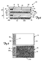
- FIG. 10 a first embodiment of a stack of sheet assemblies according to the present invention, which stack is generally designated by the reference numeral 10.
- the stack 10 includes a multiplicity of sheet assemblies 9, only 2 of which are shown in Figures 1 and 2.
- Each sheet assembly 9 comprises first and second sheets 11 and 12 having the same peripheral shape and size, with each sheet 11 and 12 having front and rear major surfaces and having first and second opposite edges 13, 14 and 15, 16 respectively.
- a first layer 18 of adhesive permanently adheres a portion of the rear surface of the first sheet 11 adjacent its first edge 13 to the front surface of the second sheet 12 adjacent its first edge 15 with the first edges 13 and 15 generally aligned.
- the first layer 18 of adhesive extends a first predetermined distance (e.g., less than half the distance) from the first edges 13, 15 toward the second edges 14, 16 of the sheets 11 and 12.
- a second layer 19 of pressure sensitive adhesive on the rear surface of the second sheet 15 of each sheet assembly 9 comprises (and in this embodiment consists only of) a first portion adhering the rear surface of the second sheet 12 of each sheet assembly 9 to the front surface of the first sheet 11 on the sheet assembly 9 beneath it in the stack 10 within the first distance from the first edges 13 and 15.
- the sheet assemblies 9 also include release means in the form of coatings of low-adhesion backsize 20 on the front surfaces of the first sheets 11 for providing first adhesion zones between the front surfaces of the first sheets 11 and the rear surfaces of the second sheets 12 of the sheet assemblies 9 in the stack 10, the first adhesion zones extending about the first predetermined distance from the first edges 13 and 15 toward the second edges 14 and 16 of the sheets 11 and 12 and providing a release force between the second layers 19 of pressure sensitive adhesive and the front surfaces of the adjacent first sheets 11 in the stack 10 which is lower than the release force of the first layers 18 of adhesive to the first and second sheets 11 and 12 to afford easy initiation of peeling of the uppermost sheet assembly 9 from the adjacent sheet assembly 9 in the stack along the first adhesion zone by pulling on the first sheet 11 of the uppermost sheet assembly 9 on the stack 10.
- the first layers 18 of adhesive that adhere the first sheets 11 to the second sheets 12 are in the shape of a rectangle spaced from the peripheral edges of the sheets 11 and 12 and nearer the center of the sheets 11 and 12 than are the second layers 19 of adhesive which are in the shape of stripe completely across the sheets 11 and 12 adjacent their first edges 13 and 15.
- edges of the second layers 19 of pressure sensitive adhesive adjacent the second edges 14 and 16 of the sheets 11 and 12 are spaced toward the first edges 13 and 15 of the sheets 11 and 12 from the edges of the first layers 18 of pressure sensitive adhesive adjacent the second edges 14 and 16 of the sheets 11 and 12 so that pulling the second edge 14 of the first sheet 11 away from the second edge 16 of the second sheet 12 in the uppermost sheet assembly 9 in the stack as is illustrated in Figure 2 will initiate peeling of the second layer 19 of pressure sensitive adhesive away from the adjacent sheet assembly 9 in the stack 10 as the top sheet assembly 9 is being removed from the stack 10.
- the sheet assemblies 9 can be used for various purposes including carbonless paper notes, form sets, or labels with a receipt portion provided by the first sheet 11, and can have indicia printed on their front surfaces. Such indicia could, for example, include bar codes, or sequential alpha numeric characters.
- the second sheets 12 preferably have a layer 21 of a release coating along their front surfaces which affords release from the layer 18 of adhesive so that the first sheet 11 can be separated from the second sheet 12 after the sheet assembly 9 is separate from the stack 10 and adhered to a substrate by the layer 19 of pressure sensitive adhesive.
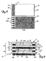
- FIG. 30 a second embodiment of a stack of sheet assemblies according to the present invention, which stack of sheet assemblies is generally designated by the reference numeral 30.
- the stack 30 of sheet assemblies includes a multiplicity of sheet assemblies 29, only 2 of which are shown in Figures 4 and 6.
- Each sheet assembly 29 comprises first and second rectangular sheets 31 and 32 having the same peripheral shape and size, with each sheet 31 and 32 having front and rear major surfaces and having first and second opposite edges 33, 34 and 35, 36 respectively.
- a first layer 38 of adhesive permanently adheres a portion of the rear surface of the first sheet 31 adjacent its first edge 33 to the front surface of the second sheet 32 adjacent its first edge 35 with the first edges 33 and 35 generally aligned.
- the first layer 38 of adhesive extends a first predetermined distance (e.g., less than half the distance) from the first edges 33, 35 toward the second edges 34, 36 of the sheets 31 and 32.
- the first sheets 31 have a transverse line of perforations 41 along the edges of the first layers of adhesive 38 adjacent the second edges 34 of the first sheets 31 so that the portions of the first sheets 31 between the perforations 41 and their second edges 34 are manually removable.
- a second layer 39 of pressure sensitive adhesive on the rear surface of the second sheet 32 of each sheet assembly 29 comprises a first portion 39a within the first distance from the first edges 33 and 35, and a second portion 39b positioned between the first adhesion zone and the second edge 36 of the second sheet 32.
- the portions 39a and 39b of the second layer 39 of pressure sensitive adhesive adhere the rear surface of the second sheet 32 of the sheet assembly 29 to the front surface of the first sheet 31 on the sheet assembly 29 beneath it in the stack 30.
- the sheet assemblies 29 also include release means in the form of coatings of low-adhesion backsize 40 on the front surfaces of the first sheets 31 and the use of less aggressive pressure sensitive adhesive in the portions 39a than in the portions 39b of the second layers of pressure sensitive adhesive 39 for providing (1) first adhesion zones between the front surfaces of the first sheets 31 and the rear surfaces of the second sheets 32 of the sheet assemblies 29 in the stack 30 which extend about the first predetermined distance from the first edges 33 and 35 toward the second edges 34 and 36 of the sheets 31 and 32 and providing a release force between the first portions 39a of second layers 39 of pressure sensitive adhesive and the front surfaces of the adjacent first sheets 31 in the stack 30 which is lower than the release force of the first layers 38 of adhesive to the first and second sheets 31 and 32 to afford easy initiation of peeling of the uppermost sheet assembly 29 from the adjacent sheet assembly 29 in the stack along the first adhesion zone by pulling on the first sheet 31 of the uppermost sheet assembly 29 on the stack 30 as is seen in Figure 6; and for providing (2) a second adhesion zone between the front surfaces of
- the first layers 38 of adhesive that adhere the first sheets 31 to the second sheets 32 are in the shape of a rectangle spaced slightly on three sides from the peripheral edges of the sheets 31 and 32, and the first portions 39a of the second layers 39 of pressure sensitive adhesive are also in the shape of a rectangle having elongate sides aligned in the stack 30 with the elongate sides of the first layers 38 of adhesive, but having opposite ends that are spaced further from the peripheral edges of the sheets 31 and 32 than are opposite ends of the first layers 38 of adhesive.
- the sheet assemblies 29 can be used for various purposes including carbonless paper notes, form sets, or labels with a receipt portion provided by the first sheet 31, and can have indicia printed on their front surfaces.
- the second sheets 32 preferably have a layer 43 of release coating along a portion of their front surfaces which enhance the graphic character of any previously printed indicia.
- FIG. 7 there is shown a third embodiment of a stack of sheet assemblies according to the present invention, which stack of sheet assemblies is generally designated by the reference numeral 50.
- the stack 50 of sheet assemblies includes a multiplicity of sheet assemblies 49, only 2 of which are shown in Figure 7.
- Each sheet assembly 49 comprises first and second rectangular sheets 51 and 52 having the same peripheral shape and size, with each sheet 51 and 52 having front and rear major surfaces and having first and second opposite edges 53, 54 and 55, 56 respectively.
- a first layer 58 of adhesive permanently adheres a portion of the rear surface of the first sheet 51 adjacent its first edge 53 to the front surface of the second sheet 52 adjacent its first edge 55 with the first edges 53 and 55 generally aligned.
- the first layer 58 of adhesive extends a first predetermined distance (e.g., less than half the distance) from the first edges 53, 55 toward the second edges 54, 56 of the sheets 51 and 52.
- the first sheets 51 have a transverse line of perforations 61 along the edges of the first layers of adhesive 58 adjacent the second edges 54 of the first sheets 51 so that the portions of the first sheets 51 between the perforations 61 and their second edges 54 are manually removable.
- a second layer 59 of pressure sensitive adhesive on the rear surface of the second sheet 55 of each sheet assembly 49 comprises a first portion 59a within the first distance from the first edges 53 and 55, and a second portion 59b positioned between the first adhesion zone and the second edge 56 of the second sheet 52.
- the portions 59a and 59b of the second layer 59 of pressure sensitive adhesive adhere the rear surface of the second sheet 52 of the sheet assembly 49 to the front surface of the first sheet 51 on the sheet assembly 49 beneath it in the stack 50.
- the sheet assemblies 49 also include release means in the form of coatings of low-adhesion backsize 60 on the front surfaces of the first sheets 51 and the use of discontinuous portions 59a consisting of triangular shaped parts with apexes adjacent the first edges 53 and 54 of the sheets and continuous portions 59b of the second layers of pressure sensitive adhesive 59 for providing (1) first adhesion zones between the front surfaces of the first sheets 51 and the rear surfaces of the second sheets 52 of the sheet assemblies 49 in the stack 50 which extend about the first predetermined distance from the first edges 53 and 55 toward the second edges 54 and 56 of the sheets 51 and 52 and providing a release force between the first portions 59a of second layers 59 of pressure sensitive adhesive and the front surfaces of the adjacent first sheets 51 in the stack 50 which is lower than the release force of the first layers 58 of adhesive to the first and second sheets 51 and 52 to afford easy initiation of peeling of the uppermost sheet assembly 49 from the adjacent sheet assembly 49 in the stack along the first adhesion zone by pulling on the first sheet 51 of the uppermost sheet assembly 49 on the
- the first layers 58 of adhesive that adhere the first sheets 51 to the second sheets 52 are in the shape of rectangles spaced slightly on three sides from the peripheral edges of the sheets 51 and 52. Pulling the second edge 54 of the first sheet 51 away from the second edge 56 of the second sheet 52 in the uppermost sheet assembly 49 in the stack will fairly easily separate the bond between the first portion 59a of the second layer of pressure sensitive adhesive 59, and will thereby initiate peeling of the more aggressive second portion 59b of the second layer 59 of pressure sensitive adhesive away from the adjacent sheet assembly 49 in the stack 50 as the top sheet assembly 49 is being removed from the stack 50.
- the sheet assemblies 49 can be used for the same purposes as the sheet assemblies 29, and can have indicia printed on their front surfaces.
- the second sheets 52 preferably have a layer 63 of release coating along a portion of their front surfaces which enhance the graphic character of any previously printed indicia.
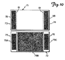
- FIG. 10 there is shown a fourth embodiment of a stack of sheet assemblies according to the present invention, which stack of sheet assemblies is generally designated by the reference numeral 70.
- the stack 70 of sheet assemblies includes a multiplicity of sheet assemblies 69, only 2 of which are shown in Figure 9.
- Each sheet assembly 69 comprises first and second rectangular sheets 71 and 72 having the same peripheral shape and size, with each sheet 71 and 72 having front and rear major surfaces and having first and second opposite edges 73, 74 and 75, 76 respectively.
- a first layer 78 of adhesive permanently adheres a portion of the rear surface of the first sheet 71 adjacent its first edge 73 to the front surface of the second sheet 72 adjacent its first edge 75 with the first edges 73 and 75 generally aligned
- a third layer 98 of adhesive permanently adheres a portion of the rear surface of the first sheet 71 adjacent its second edge 74 to the front surface of the second sheet 72 adjacent its second edge 76 with the first and second edges 73, 75 and 74, 76 generally aligned.
- the first and third layers 78 and 98 of adhesive extend a first predetermined distance (e.g., less than one third the distance) from the edges 73, 74, 75 and 76 which they are adjacent toward the opposite edges edges 73, 74, 75, and 76 of the sheets 71 and 72.
- the first sheets 71 have spaced transverse lines of perforations 81 along the adjacent edges of the first and third layers 78 and 98 of adhesive 78 so that the portions of the first sheets 71 between the perforations 41 are manually removable.
- a second layer 79 of pressure sensitive adhesive on the rear surface of the second sheet 72 of each sheet assembly 69 comprises a first portion 79a within the first distance from the first edges 73 and 75, a third portion 79c within the first distance from the second edges 74 and 76, and a second central portion 79b positioned between the first and third portions 79a and 79c.
- the portions 79a, 79b and 79c of the second layer 79 of pressure sensitive adhesive adhere the rear surface of the second sheet 72 of the sheet assembly 69 to the front surface of the first sheet 71 on the sheet assembly 69 beneath it in the stack 70.
- the sheet assemblies 69 also include release means in the form of coatings of low-adhesion backsize 40 on the front surfaces of the first sheets 71 and the use of less of the same adhesive or less aggressive pressure sensitive adhesive in the portions 79a and 79c than in the portions 79b of the second layers of pressure sensitive adhesive 79 for providing (1) first adhesion zones between the front surfaces of the first sheets 71 and the rear surfaces of the second sheets 72 of the sheet assemblies 69 in the stack 70 which extend about the first predetermined distance from the edges 73, 74, 75 and 76 of the sheets 71 and 72 and provide a release force between the first and third portions 79a and 79c of the second layers 79 of pressure sensitive adhesive and the front surfaces of the adjacent first sheets 71 in the stack 70 which is lower than the release force of the first layers 78 of adhesive to the first and second sheets 71 and 72 to afford easy initiation of peeling of the uppermost sheet assembly 69 from the adjacent sheet assembly 69 in the stack along the first and third adhesion zone by pulling on the first sheet 71
- the first and third layers 78 and 98 of adhesive that adhere the first sheets 71 to the second sheets 72 are in the shape of a rectangles spaced slightly on three sides from the peripheral edges of the sheets 71 and 72, and the first and third portions 79a and 79c of the second layers 79 of pressure sensitive adhesive are also in the shape of rectangles having elongate sides aligned in the stack 70 with the elongate sides of the first and third layers 78 and 98 of adhesive, respectively, but having opposite ends that are spaced further from the peripheral edges of the sheets 71 and 72 than are opposite ends of the first and third layers 78 and 98 of adhesive.
- the sheet assemblies 69 can be used for various purposes including carbonless paper notes, form sets, or labels with a receipt portion provided by the first sheet 71, and can have indicia printed on their front surfaces.
- the second sheets 72 preferably have a layer 83 of release coating along a portion of their front surfaces which enhance the graphic character of any previously printed indicia.
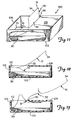
- FIGs 11 through 13 illustrate a container 100 from which sheet assemblies 29 or 49 from the stacks 30 or 50 of sheet assemblies can be dispensed, which container is illustrated in combination with the stack 30 of sheet assemblies 29 illustrated in Figures 4, 5 and 6.
- the container 100 comprises walls around the stack of sheet assemblies, including a bottom wall 102 supporting the stack 30 of sheet assemblies 29, side walls along and closely spaced from the edges of the sheets 31 and 32 in the stack of sheet assemblies 29 including a first end wall 106 along the first edges 33 and 35 of the sheets 31 and 32 in the stack 30 of sheet assemblies 29, and a top wall 109 along the top of the stack 30 of sheet assemblies 29.
- the top wall 109 has an edge surface 110 spaced from the first end wall 106 to provide an opening 112 therebetween, which edge surface 110 is spaced from the end wall 106 by a distance greater than said first predetermined distance that the layer 38 of adhesive extends so that with an end portion of the first sheet 31 adjacent its second edge 34 of the uppermost sheet assembly 29 in the stack 29 projecting through the opening 112, tension applied manually to that end portion will first cause separation of first portion 39a of the second layer of pressure sensitive adhesive 39 on the second sheet 32 of the uppermost sheet assembly 29 in the stack 30 from the second sheet assembly 29 in the stack 29 along the first adhesion zone by bending that second sheet 32 around the edge surface 110 ( Figure 12), whereafter the second sheet 32 of the uppermost sheet assembly 29 in the stack 30 will be pulled along the inner surface of the top wall 109 and around the edge surface 110 while carrying with it the first sheet 31 of the second sheet assembly 29 in the stack 30 ( Figure 12) until the end portion of the second sheet 32 of the uppermost sheet assembly 29 in the stack 30 carries the first sheet 31 of the
- a stack of sheet assemblies of the embodiment illustrated in Figures 1, 2, and 3 were produced by first preparing a plurality of the first and second sheets 11 and 12, then laminating them together to form the sheet assemblies 9, and then stacking the sheet assemblies 9.
- the first sheet 11 was prepared by apsheeting an 12.7 mm strip of a 0.13 mm thick tackified acrylic transfer tape (available from 3M as Scotch TM brand #969 Adhesive Transfer Tape) 3.2 mm from the 118 mm edge on the face without a release coating of the liner Daubert 4020 (commercially available from Daubert Coated Products Company) forming an 118 mm wide and 81 mm long sheet.
- the second sheet 12 was prepared on a separate paper of the same size.
- the paper was printed and coated with the silicone release system of 96 parts Syl-Off R 7610 and 4 parts Syl-Off R 7611 (commercially available from Dow Corning Corporation) and cured. To the opposite side was coated an 12.7 mm strip of .03 mm thick adhesive Duro-tak R 34-4142 (commercially available from National Starch and Chemical Corporation) 4.8 mm from the 118 mm wide edge.
- the sheet assemblies 9 were found to be easily separated from the stack 10 by merely grasping the first sheet 11 of the uppermost sheet assembly 9 and lifting. As described previously, when the first sheet 11 of the uppermost sheet assembly 9 was at the top of the stack 10, the uppermost sheet assembly 9 was dispensed while peeling parallel to the 81 mm edge of the stack 10.
- the then uppermost sheet assembly 9 sheet was dispensed while peeling parallel to the 118 mm edge.
- the adhesive coating 18 on the removed sheet assembly 9 was adhered to a substrate, the first sheet 11 could be easily removed from the second sheet 12 and adhered to another substrate by the first layer of adhesive 18.
- a stack of labels generally of the form shown in Figure Nos. 9 and 10 were produced by printing paper and then coating it with the silicone release system of 96 parts Syl-Off R 7610 and 4 parts Syl-Off R 7611 and curing the release material.
- To the opposite side of the top sheet were coated 12.7 mm strips of 0.03 mm thick adhesive Duro-tak R 34-4142.
- the adhesive bars on the top sheet were approximately 9.5 mm wide and 67.0 mm long on the 82.5 mm long and 127.0 mm wide sheet.
- the bottom sheet was printed and coated with the same release material, as the pictured sheet 22. The same adhesive was used to provide bars 9.5 mm wide and 65.0 mm long.
- the central block of adhesive 66 mm long and 87 mm wide was also applied in the center of the sheet.
- the sheets were laminated, stacked and trimmed. The sheets easily dispensed and were applied to various surfaces.
- the top sheet was permanently bonded to the bottom using the top sheet's adhesive. The sheets bonded to surfaces, and the central section of the top sheet was easily detached along the lines of weakness formed by a perforation.
- a stack of label or sheet assemblies of the embodiment illustrated in Figures 4, 5, and 6 were produced using the paper, release material, and adhesive described in Example No. 2.
- the first sheet 31 was prepared as above, except only a single layer or bar 38 of adhesive was applied, and only a single corresponding line of weakness was provided by perforations 41.
- the second sheet 32 was prepared as in Example 2 above, except only a single bar or layer portion 39a of adhesive was provided, and the second portion 39b of the layer 39 of pressure sensitive adhesive was extended to be 98 mm wide.
- the sheets were laminated to form the sheet assemblies 29, stacked and trimmed.
- the sheets assemblies 29 easily dispensed from the stack 30 and were applied to various surfaces.
- the first sheet 31 was permanently bonded to the second sheet 32 by the layer 38 of adhesive. After a dispensed sheet assembly was adhered to a surface by the layer of pressure sensitive adhesive 39, the portion of the first sheet 31 between the perforations 41 and its edge 34 was easily detached along the perforations 41.
- a stack of label or sheet assemblies 49 generally of the embodiment shown in Figures 7 and 8 were produced as in Example No. 3, except that the pattern of the first portion 59a of the layer 59 of pressure sensitive adhesive was changed. That pattern was made as series of six isosceles triangles with an 8 mm base and 12 mm sides, spaced 4 mm between bases.
- the sheet assemblies 50 easily dispensed and were applied to various surfaces.
- the first sheet 51 was permanently bonded to the second sheet 52 by the layer 58 of adhesive.
- the first sheet 51 was permanently bonded to the second sheet 52 by the layer 58 of adhesive.
- a container or dispenser for label or sheet assemblies generally of the embodiment shown in Figure 11 was made for a stack 50 of label or sheet assemblies 49 of the embodiment described in Example No. 4.
- the dispenser or container 100 was formed from a 0.51 mm card stock material.
- the stack 50 was 117 mm long and 77 mm wide, the side walls of the dispenser 100 were 22 mm high, the base or bottom wall 102 was 86 mm wide and 122 mm long, and the top wall 109 was 86 mm wide and 92 mm long, leaving an exit orifice or opening 112 82 mm wide and 33 mm long.
- the layer of pressure sensitive adhesive 59 on the second sheet 52 adjacent the bottom wall 102 was adhered thereto, and the first sheet 51 of the sheet assembly 49 adjacent the top wall 109 was positioned so that it projected through the opening 112. Sheet assemblies 49 were easily dispensed from the dispenser 100 and used in the manner described above.
- the dispenser 100 could be used in horizontal, vertical, or other attitudes.
- each sheet assembly could contain more than two sheets adhered together in the manners that the first sheets are adhered to the second sheets in the above embodiments.
- the scope of the present invention should not be limited to the structures described in this application, but only by structures described by the claims.
Landscapes
- Engineering & Computer Science (AREA)
- Physics & Mathematics (AREA)
- Theoretical Computer Science (AREA)
- Mathematical Physics (AREA)
- Business, Economics & Management (AREA)
- Educational Administration (AREA)
- Educational Technology (AREA)
- General Physics & Mathematics (AREA)
- Adhesive Tapes (AREA)
- Laminated Bodies (AREA)
Claims (12)
- Stapel (10;30;50;70) von Bogengruppen (9;29;49;69), wobei jede Bogengruppe (9;29;49;69) folgendes umfaßt:
erste und zweite Bögen (11,12;31,32;51,52;71,72) mit jeweils einer vorderen und einer hinteren Hauptfläche und einer ersten und einer zweiten einander entgegengesetzten Kante (13,14,15,16;33,34,35,36;53,54,55,56;73,74,75,76),
eine erste Klebstoffschicht (18;38;58;78), die einen Abschnitt der Rückseite des ersten Bogens (11;31;51;71) im Bereich der ersten Kante (13;33;53;73) des ersten Bogens (11;31;51;71) mit der Vorderseite des zweiten Bogens (12;32;52;72) im Bereich der ersten Kante (15;35;55;75) des zweiten Bogens (12;32;52;72) so verklebt, daß die ersten Kanten (13,15;33,35;53,55;73,75) im allgemeinen fluchten, wobei die erste Klebstoffschicht (18;38;58;78) eine erstes vorbestimmtes Stück weit von den ersten Kanten (13,15;33,35;53,55;73,75) in Richtung zu den zweiten Kanten (14,16;34,36;54,56;74,76) der Bögen (11,12;31,32;51,52;71,72) reicht, und
eine zweite Haftkleberschicht (19;39;59;79) auf der Rückseite des zweiten Bogens (12;32;52;72), wobei die zweite Haftkleberschicht (19;39;59;79) einen ersten Abschnitt umfaßt, der die Rückseite des zweiten Bogens (12;32;52;72) der Bogengruppe (9;29;49;69) mit der Vorderseite des ersten Bogens (11;31;51;71) der in dem Stapel (10;30;50;70) darunterliegenden Bogengruppe (9;29;49;69) in dem ersten Stück hinter den ersten Kanten (13,15;33,35;53,55;73,75) verklebt,
wobei die Bogengruppen (9;29;49;69) Trenneinrichtungen umfassen, um erste Klebezonen zwischen den Vorderseiten der ersten Bögen (11;31;51;71) und den Rückseiten der zweiten Bögen (12;32;52;72) der Bogengruppen (9;29;49;69) in dem Stapel (10;30;50;70) zu schaffen, wobei die erste Klebezone etwa das erste Stück weit von den ersten Kanten (13,15;33,35;53,55;73,75) in Richtungen zu den zweiten Kanten (14,16;34,36;54,56;74,76) der Bögen (11,12;31,32;51,52;71,72) reicht, und um eine Ablösekraft zwischen den ersten Abschnitten der zweiten Klebstoffschichten (19;39;59;79) und den Vorderseiten der benachbarten ersten Bögen (11;31;51;71) in dem Stapel (10;30;50;70) zu erzeugen, die niedriger ist als die Ablösekraft der ersten Klebstoffschichten (18;38;58;78) auf den ersten und zweiten Bögen (11,12;31;32;51,52;71,72), damit die oberste Bogengruppe (9;29;49;69) leicht von der benachbarten Bogengruppe (9;29;49;69) in dem Stapel (10;30;50;70) entlang der ersten Klebezone abgezogen werden kann, indem an dem ersten Bogen (11;31;51;71) der obersten Bogengruppe (9;29;49;69) in dem Stapel (10;30;50;70) gezogen wird. - Stapel (10) von Bogengruppen (9) nach Anspruch 1, bei dem die Kanten der zweiten Haftkleberschichten (19) im Bereich der zweiten Kanten (16) der Bögen (11,12) in Richtung zu den ersten Kanten (13) der Bögen (11,12) von den Kanten der ersten Haftkleberschichten (18) im Bereich der zweiten Kanten (14,16) der Bögen (11,12) beabstandet sind, so daß durch Wegziehen der zweiten Kante (14) des ersten Bogens (11) der obersten Bogengruppe (9) in dem Stapel (10) von der zweiten Kante (16) des zweiten Bogens (12) der obersten Bogengruppe (9) in dem Stapel (10) die zweite Haftkleberschicht (19) allmählich von der benachbarten Bogengruppe (9) in dem Stapel (10) weggezogen wird.
- Stapel (30;50;70) von Bogengruppen (29;49;69) nach Anspruch 1, bei dem die zweiten Haftkleberschichten (39;59;79), die die Rückseiten der zweiten Bögen (32;52;72) der Bogengruppen (29;49;69) mit den Vorderseiten der ersten Bögen (31;51;71) der in dem Stapel (30;50;70) darunterliegenden Bogengruppen (29;49;69) verkleben, zweite Abschnitte umfassen, die zwischen den ersten Klebezonen und den zweiten Kanten der zweiten Bögen (32;52;72) liegen, und bei dem die Trenneinrichtung zweite Klebezonen zwischen den Vorderseiten der ersten Bögen (31;51;71) und den Rückseiten der zweiten Bögen (32;52;72) in dem Stapel (30;50;70) im Bereich der zweiten Abschnitte schafft, wobei die zweiten Klebezonen eine Ablösekraft besitzen, die größer ist als die geringe Ablösekraft in den ersten Klebezonen und so groß ist, daß benachbarte Bogengruppen (29;49;69) in dem Stapel (30;50;70) fest miteinander verklebt werden, während die oberste Bogengruppe (29;49;69) in dem Stapel (30;50;70) entlang der zweiten Klebezone kontinuierlich abgezogen werden kann, nachdem mit dem Abziehen entlang der ersten Klebezone begonnen wurde.
- Stapel (30;50;70) von Bogengruppen (29;49;69) nach Anspruch 1, bei dem die ersten Bögen (31;51;71) entlang der Kanten der ersten Klebstoffschichten im Bereich der zweiten Kanten der ersten Bögen (31;51;71) in Querrichtung perforiert sind.
- Stapel (70) von Bogengruppen (69) nach Anspruch 1, bei dem die Bogengruppen (69) jeweils eine dritte Klebstoffschicht (98) umfassen, die einen Abschnitt der Rückseite des ersten Bogens (71) im Bereich der zweiten Kante (74) des ersten Bogens (71) mit der Vorderseite des zweiten Bogens (72) im Bereich der zweiten Kante (76) des zweiten Bogens (72) bei im allgemeinen fluchtenden zweiten Kanten (74, 76) verkleben, wobei die dritte Klebstoffschicht (98) etwa gleich weit wie das erste vorbestimmte Stück von den zweiten Kanten (74, 76) zu den ersten Kanten (73, 75) der Bögen (71, 72) reicht, und wobei die ersten Bögen (71) entlang benachbarter Kanten der ersten und der dritten Klebstoffschicht (78, 98) in Querrichtung perforiert sind.
- Stapel (10;30;50;70) von Bogengruppen (9;29;49;69) nach Anspruch 1, bei dem die zweiten Haftkleberschichten auf der Rückseite der zweiten Bögen (12;32;52;72) gleichmäßige Überzüge aus dem gleichen Haftkleber sind, und bei dem die Trenneinrichtung Schichten aus einer schwach klebenden Rückenappretur auf den Abschnitten der Vorderseiten der ersten Bögen (11;31;51;71) in den ersten Klebezonen umfaßt.
- Stapel (50) von Bogengruppen (49) nach Anspruch 1, bei dem die zweiten Haftkleberschichten auf den Rückseiten der ersten Bögen (51) in den ersten Klebezonen nicht durchgängig sind, um wenigstens einen Abschnitt der Trenneinrichtung bereitzustellen.
- Stapel (30) von Bogengruppen (29) nach Anspruch 1, bei dem die zweiten Haftkleberschichten unterschiedliche Zusammensetzungen in dem ersten und zweiten Abschnitt aufweisen, um wenigstens Teile der Trenneinrichtung bereitzustellen.
- Stapel (10) von Bogengruppen (9) nach Anspruch 2, bei dem die Trenneinrichtung Schichten (20) aus einer schwach klebenden Silikonappretur an den Vorderseiten der ersten Bögen (11) in der ersten Klebezone umfaßt, und die zweiten Haftkleberschichten (19) auf den Rückseiten der zweiten Bögen (12) gleichmäßig sind, die gleiche Klebstoffzusammensetzung besitzen und an Glas mit einer Klebekraft von 111,6 Gramm pro Zentimeter (10 Unzen pro Zoll) haften.
- Stapel (10;30;50;70) von Bogengruppen (9;29;49;69) nach Anspruch 1, bei dem die ersten und zweiten Bögen (12;32;52;72) die gleiche Umfangsgröße und die gleiche Form besitzen, die Umfänge in dem Stapel (10;30;50;70) jeweils fluchten, und auf die Vorderseiten Zeichen aufgedruckt sind.
- Stapel (10;30;50;70) von Bogengruppen (9;29;49;69) nach Anspruch 1, bei dem die Haftkleberschichten Acrylsäure in einer der Klebezonen und Gummiharz in der anderen der Klebezonen enthalten.
- Stapel (30;50) von Bogengruppen (29;49) nach Anspruch 1 in Kombination mit einem Behälter (100), wobei der Behälter (100) Wände um den Stapel (30;50) von Bogengruppen (29;49) umfaßt mit einer Bodenwand (102), auf der der Stapel (30;50) von Bogengruppen (29;49) aufliegt, Seitenwänden entlang und dicht an den Kanten der Bögen in dem Stapel (30;50) von Bogengruppen (29;49) mit einer ersten Stirnwand (106) entlang der ersten Kanten (33,35;53,55) der Bögen in dem Stapel (30;50) von Bogengruppen (29;49), und einer oberen Wand (109) an der Oberseite des Stapels (30;50) von Bogengruppen (29;49), wobei die obere Wand (109) eine Kantenfläche (110) aufweist, die von der ersten Stirnwand (106) so beabstandet ist, daß dazwischen eine Öffnung (112) entsteht, und wobei die Kantenfläche (110) der oberen Wand (109) weiter als das erste vorbestimmte Stück von der ersten Stirnwand (106) beabstandet ist, so daß dann, wenn ein Endabschnitt des ersten Bogens (31;51) im Bereich der zweiten Kante (34,54) des ersten Bogens (31,51) der obersten Bogengruppe (29;49) in dem Stapel (30;50) durch die Öffnung (112) ragt, ein mit der Hand auf den Endabschnitt ausgeübter Zug zunächst bewirken wird, daß sich der zweiten Bogen (32;53) der obersten Bogengruppe (29;49) in dem Stapel (30;50) von der zweiten Bogengruppe (29;49) in dem Stapel (30;50) entlang der ersten Klebezone löst, indem dieser zweite Bogen (32;52) um die Kantenfläche (110) gebogen wird, und anschließend wird der zweite Bogen (32;52) der obersten Bogengruppe (29;49) in dem Stapel (30;50) an der oberen Wand (109) des Behälters entlang und um die Kantenfläche (110) herum gezogen, wobei er den ersten Bogen (31;51) der zweiten Bogengruppe (32;52) in dem Stapel (30;50) mitnimmt, bis der Endabschnitt des zweiten Bogens (32;52) der obersten Bogengruppe (29;49) in dem Stapel (30;50) den ersten Bogen (31;51) der zweiten Bogengruppe (24;49) in dem Stapel (30;50) durch die Öffnung (112) mitnimmt und anschließend abgezogen wird, so daß der erste Bogen (31;51) der ursprünglich zweiten Bogengruppe (24;49) in dem Stapel (30;50) so durch die Öffnung (112) ragt, daß er ebenfalls in der oben beschriebenen Weise von Hand hindurchgezogen werden kann.
Applications Claiming Priority (2)
| Application Number | Priority Date | Filing Date | Title |
|---|---|---|---|
| US07/531,870 US5050909A (en) | 1990-06-01 | 1990-06-01 | Stack of sheet assemblies |
| US531870 | 1990-06-01 |
Publications (2)
| Publication Number | Publication Date |
|---|---|
| EP0459645A1 EP0459645A1 (de) | 1991-12-04 |
| EP0459645B1 true EP0459645B1 (de) | 1995-03-22 |
Family
ID=24119390
Family Applications (1)
| Application Number | Title | Priority Date | Filing Date |
|---|---|---|---|
| EP91304215A Expired - Lifetime EP0459645B1 (de) | 1990-06-01 | 1991-05-10 | Stapel der Bogenzusammenstellungen |
Country Status (7)
| Country | Link |
|---|---|
| US (1) | US5050909A (de) |
| EP (1) | EP0459645B1 (de) |
| JP (1) | JP2547033Y2 (de) |
| KR (1) | KR0119544Y1 (de) |
| AU (1) | AU640475B2 (de) |
| CA (1) | CA2040512A1 (de) |
| DE (1) | DE69108294T2 (de) |
Families Citing this family (69)
| Publication number | Priority date | Publication date | Assignee | Title |
|---|---|---|---|---|
| US5195265A (en) * | 1989-10-05 | 1993-03-23 | Klingenberg Hans Ulrich | Labelling method and system having adhesive over a majority of rear surface |
| US5199924A (en) * | 1991-06-20 | 1993-04-06 | Uarco Incorporated | Structure for and method of making overlapping multipart business form unit sets |
| US5267899A (en) * | 1992-01-23 | 1993-12-07 | Moore Business Forms, Inc. | Defective equipment window stickers |
| WO1994007228A2 (en) * | 1992-09-22 | 1994-03-31 | Corporate Culture Limited | Holder for repositionable notes |
| US5618062A (en) * | 1992-11-09 | 1997-04-08 | Minnesota Mining And Manufacturing Company | Note or note pad preparation method |
| US5382055A (en) * | 1992-11-09 | 1995-01-17 | Minnesota Mining And Manufacturing Company | Note or note pad preparation method |
| DE4305081C2 (de) | 1993-02-19 | 1996-08-01 | Minnesota Mining & Mfg | Verfahren und Vorrichtung zum Auftragen von Haftkleber auf Bogen aus Papier oder dergleichen Material |
| US5437476A (en) * | 1993-04-13 | 1995-08-01 | Moore Business Forms, Inc. | Multipage bound booklet having pressure sealed binding |
| US5458378A (en) * | 1993-04-22 | 1995-10-17 | Crawford; David | Record keeping system |
| US5366776A (en) * | 1993-06-29 | 1994-11-22 | Minnesota Mining And Manufacturing Company | Pad assembly |
| US5411168A (en) * | 1993-08-03 | 1995-05-02 | Minnesota Mining And Manufacturing Company | Sheet dispenser and dispenser subassemblies |
| US5397117A (en) * | 1993-10-05 | 1995-03-14 | Minnesota Mining And Manufacturing Company | Sheet dispenser |
| US5575574A (en) * | 1994-04-06 | 1996-11-19 | Minnesota Mining And Manufacturing Company | Sheet composite adapted to be printed |
| KR950031539A (ko) * | 1994-05-20 | 1995-12-18 | 조명호 | 인쇄물용 위치표시수단 |
| DE69506405T2 (de) * | 1994-06-13 | 1999-07-29 | Minnesota Mining And Mfg. Co., Saint Paul, Minn. | Bindevorrichtung |
| US5518144A (en) * | 1994-06-21 | 1996-05-21 | Minnesota Mining And Manufacturing Company | Dispenser package |
| US5939161A (en) | 1994-06-21 | 1999-08-17 | Minnesota Mining And Manufacturing Company | Adhesive tape strip and tape flag pads with center tabbed leader strip |
| US5520308A (en) * | 1994-11-21 | 1996-05-28 | The Procter & Gamble Company | Sequential dispensing of tissues and dispenser therefor |
| US5578352A (en) * | 1995-04-04 | 1996-11-26 | Moore Business Forms, Inc. | Strip coated adhesive products |
| US5524929A (en) * | 1995-05-02 | 1996-06-11 | Minnesota Mining And Manfacturing Company | Binding assembly |
| US5967555A (en) * | 1995-05-12 | 1999-10-19 | Samelian; John K. | Removable binding system |
| JPH091719A (ja) * | 1995-06-21 | 1997-01-07 | Minnesota Mining & Mfg Co <3M> | 目隠し転写用品 |
| US5755356A (en) * | 1996-04-15 | 1998-05-26 | Minnesota Mining And Manufacturing Company | Compressible sheet dispenser |
| US5697518A (en) * | 1996-06-18 | 1997-12-16 | Minnesota Mining And Manufacturing Company | Header padded stationery equipped with adhesive sheet pads recessed within the header |
| US5827591A (en) * | 1996-10-08 | 1998-10-27 | Tricor Direct, Inc. | Removable adhesive notes for an industrial setting |
| US5948494A (en) * | 1997-05-29 | 1999-09-07 | Levin; Herbert L. | Composite sheet and sheet stack |
| US6153278A (en) * | 1997-06-17 | 2000-11-28 | Taylor Corporation | Pad of adhesively secured sheets |
| US6406244B1 (en) | 1998-07-09 | 2002-06-18 | Frederic P. A. Le Riche | Stack of sheets with repositionable adhesive alternating between opposite edges and containing one or more sheets different from other sheets |
| EP0890451A1 (de) * | 1997-07-11 | 1999-01-13 | Minnesota Mining And Manufacturing Company | Stapel mit wiederplazierbarern Blättern in alternierender Klebeseitenanordnung mit einem oder mehreren sich voneinander unterscheidenden Blättern |
| US6286871B1 (en) | 1998-05-12 | 2001-09-11 | Carol Wilson Fine Arts, Inc. | Pads of embossed, self-stick paper and process and apparatus for making same |
| EP0968839A1 (de) * | 1998-07-02 | 2000-01-05 | Blockfabrik Lichtensteig AG | Block |
| EP0968840B1 (de) * | 1998-07-02 | 2003-02-19 | Blockfabrik Lichtensteig AG | Block bestehend aus mehreren aufeinanderliegenden blattförmigen Erzeugnissen und Verwendung des Blocks |
| US6102247A (en) * | 1998-07-29 | 2000-08-15 | 3M Innovative Properties Company | Trifold dispenser blank for tape strip pads |
| US6286712B1 (en) * | 1999-09-24 | 2001-09-11 | Paper Converting Machine Co | Stack formed from connected groups of interfolded sheets |
| DE29916945U1 (de) | 1999-09-25 | 1999-12-16 | Kommunal- und Behörden-Verlag OHG, 86653 Monheim | Formularsatz |
| US20020011304A1 (en) | 2000-05-03 | 2002-01-31 | Elijah Abron | Substrate sheets with removable strip |
| JP2002321469A (ja) * | 2001-04-26 | 2002-11-05 | Kokuyo Co Ltd | 付箋紙 |
| US6612462B2 (en) | 2001-05-31 | 2003-09-02 | Kimberly-Clark Worldwide, Inc. | Stack of fan folded material and combinations thereof |
| US7081080B2 (en) | 2001-05-31 | 2006-07-25 | Kimberly-Clark Worldwide, Inc. | Stack of fan folded material and combinations thereof |
| US6550633B2 (en) | 2001-05-31 | 2003-04-22 | Kimberly-Clark Worldwide, Inc. | Process for joining wet wipes together and product made thereby |
| US6905748B2 (en) * | 2001-05-31 | 2005-06-14 | Kimberly-Clark Worldwide, Inc. | Stack of fan folded material and combinations thereof |
| DE10219875A1 (de) * | 2002-03-02 | 2003-10-16 | Tesa Ag | Blattstapel |
| US6971542B2 (en) * | 2002-12-13 | 2005-12-06 | Kimberly-Clark Worldwide, Inc. | Reach-in wipes with enhanced dispensibility |
| US6848595B2 (en) | 2002-12-13 | 2005-02-01 | Kimberly-Clark Worldwide, Inc. | Wipes with a pleat-like zone along the leading edge portion |
| US7487566B2 (en) * | 2003-09-04 | 2009-02-10 | The Evercare Company | Adhesive roller |
| US20050050660A1 (en) * | 2003-09-04 | 2005-03-10 | The Evercare Company | Adhesive roller |
| US7735872B1 (en) * | 2003-10-16 | 2010-06-15 | Arkwright George A | Adhesive fastener assembly and method for removably mounting papers |
| US7181878B2 (en) * | 2003-10-21 | 2007-02-27 | Ward/Kraft, Inc. | Label, or business form/label combination having multiple layered or patterned coated adhesives and methods of making same |
| US8100435B1 (en) | 2006-04-03 | 2012-01-24 | Arkwright George A | Adhesive fastener binder and method of filing a paper |
| US10209265B2 (en) * | 2007-04-19 | 2019-02-19 | Quest Diagnostics Investments Incorporated | Chain of custody forms and methods |
| US20100230429A1 (en) * | 2007-08-07 | 2010-09-16 | Jacobs Joy B | Chewing gum pocket |
| US20090038964A1 (en) * | 2007-08-07 | 2009-02-12 | Jacobs Joy B | Chewing gum pocket |
| US8147643B1 (en) * | 2008-06-06 | 2012-04-03 | Chicago Tag & Label, Inc. | Bar code label book single pass manufacturing process |
| JP5746971B2 (ja) | 2008-11-13 | 2015-07-08 | スリーエム イノベイティブ プロパティズ カンパニー | 接着ラベル積層物、及び積層物を基材に適用するための方法 |
| ES2402488T3 (es) * | 2008-12-31 | 2013-05-06 | Aki, Inc. | Dispositivo para contener y liberar un material de muestra |
| US20100252567A1 (en) * | 2009-04-06 | 2010-10-07 | 3M Innovative Properties Company | Padded labels dispenser and method of dispensing labels |
| US9272830B2 (en) | 2009-08-24 | 2016-03-01 | Aki, Inc. | Unitized package of card and fluid vessel |
| ES2528244T3 (es) | 2009-08-24 | 2015-02-05 | Aki, Inc. | Envase unificado y método de preparación del mismo |
| CA137791S (en) | 2010-02-08 | 2011-06-13 | Avery Dennison Corp | Note sheet pad |
| US20110195217A1 (en) * | 2010-02-08 | 2011-08-11 | Sato Jay K | Note sheet and pads thereof and related method |
| US8778474B2 (en) | 2010-02-08 | 2014-07-15 | Ccl Label, Inc. | Repositionable medium and stack thereof |
| USD679753S1 (en) | 2010-02-08 | 2013-04-09 | Avery Dennison Corporation | Note sheets and related pads of note sheets |
| US8528731B2 (en) | 2010-04-21 | 2013-09-10 | Ccl Label, Inc. | Labels, related pads thereof, and related methods |
| USD683397S1 (en) | 2010-04-21 | 2013-05-28 | Avery Dennison Corporation | Pad of labels |
| JP6704235B2 (ja) * | 2015-10-15 | 2020-06-03 | スリーエム イノベイティブ プロパティズ カンパニー | ディスペンサー及びシールド |
| USD862601S1 (en) | 2016-07-07 | 2019-10-08 | Ccl Label, Inc. | Carrier assembly |
| DE102017127893A1 (de) * | 2017-11-24 | 2019-05-29 | Certoplast Technische Klebebänder Gmbh | Verfahren zur Herstellung einer Ummantelung für langgestrecktes Gut |
| US12060211B2 (en) * | 2019-02-19 | 2024-08-13 | Ranpak Corp. | Bound pad of expandable slit-sheet stock material |
| EP3939906B1 (de) * | 2020-07-15 | 2024-02-14 | Storopack Hans Reichenecker GmbH | Bereitstellung von polstermaterial zum umhüllen von mindestens einem objekt |
Family Cites Families (14)
| Publication number | Priority date | Publication date | Assignee | Title |
|---|---|---|---|---|
| US3332829A (en) * | 1964-02-18 | 1967-07-25 | Avery Adhesive Products Inc | Article for multiplicate marking |
| CH452479A (de) * | 1966-12-08 | 1968-05-31 | Eugster Walter | Papierblock mit selbstklebenden Einzelblättern |
| US3524782A (en) * | 1967-03-10 | 1970-08-18 | Duwayne F Buske | Combination protection label and coupon |
| US3508754A (en) * | 1967-09-28 | 1970-04-28 | Chromographic Press Inc | Stacked sheet article with release coated removable areas |
| US4281762A (en) * | 1980-03-17 | 1981-08-04 | Graphic Resources, Incorporated | In-store coupon and methods |
| US4416392A (en) * | 1981-02-19 | 1983-11-22 | Minnesota Mining & Manufacturing Company | Dispenser for adhesive coated sheet material |
| DE8322955U1 (de) * | 1983-08-09 | 1984-01-26 | Publiplast Werbemittel Gmbh, 7759 Immenstaad | Notizvorrichtung |
| US4583765A (en) * | 1983-10-17 | 1986-04-22 | Emanuel Messinger | Multi-copy self-stick label set |
| JPS61139058A (ja) * | 1984-12-11 | 1986-06-26 | Seiko Epson Corp | 半導体製造装置 |
| DE3522626A1 (de) * | 1985-06-25 | 1987-01-08 | Merz & Co Gmbh & Co | Loeslicher kollagen-schwamm |
| US4768810A (en) * | 1986-06-23 | 1988-09-06 | Minnesota Mining And Manufacturing Company | Fanfolded tablet of a web which is separable into sheets each bearing a pressure-sensitive adhesive pattern |
| US4714276A (en) * | 1986-09-25 | 1987-12-22 | Moore Business Forms, Inc. | Multiple-part form with one or more parts removably retained by temporary adhesion in stub area |
| US4895746A (en) * | 1989-03-01 | 1990-01-23 | Minnesota Mining And Manufacturing Company | Stack of pressure sensitive adhesive coated sheets |
| US4955640A (en) * | 1989-08-25 | 1990-09-11 | Moore Business Forms, Inc. | Z-folded packing list/invoice |
-
1990
- 1990-06-01 US US07/531,870 patent/US5050909A/en not_active Expired - Lifetime
-
1991
- 1991-04-15 CA CA002040512A patent/CA2040512A1/en not_active Abandoned
- 1991-04-22 AU AU75260/91A patent/AU640475B2/en not_active Ceased
- 1991-05-10 DE DE69108294T patent/DE69108294T2/de not_active Expired - Fee Related
- 1991-05-10 EP EP91304215A patent/EP0459645B1/de not_active Expired - Lifetime
- 1991-05-31 JP JP1991040504U patent/JP2547033Y2/ja not_active Expired - Lifetime
- 1991-05-31 KR KR2019910008087U patent/KR0119544Y1/ko not_active Expired - Fee Related
Also Published As
| Publication number | Publication date |
|---|---|
| DE69108294T2 (de) | 1995-10-12 |
| KR920000506U (ko) | 1992-01-27 |
| JP2547033Y2 (ja) | 1997-09-03 |
| KR0119544Y1 (ko) | 1998-07-01 |
| AU7526091A (en) | 1991-12-05 |
| CA2040512A1 (en) | 1991-12-02 |
| DE69108294D1 (de) | 1995-04-27 |
| EP0459645A1 (de) | 1991-12-04 |
| AU640475B2 (en) | 1993-08-26 |
| JPH0744311U (ja) | 1995-11-14 |
| US5050909A (en) | 1991-09-24 |
Similar Documents
| Publication | Publication Date | Title |
|---|---|---|
| EP0459645B1 (de) | Stapel der Bogenzusammenstellungen | |
| EP0385647B1 (de) | Stapel von Folien mit druckempfindlicher Klebstoffbeschichtung | |
| EP0338028B1 (de) | Bogen und ausgabepackung dafür | |
| US6756100B2 (en) | Tape strip pads and dispenser and method of dispensing individual tape strips | |
| US4863772A (en) | Label stock with dry separation interface | |
| US7185785B2 (en) | Tape sheet pads and dispenser and method of dispensing individual tape sheets from such pads | |
| EP0353906A2 (de) | Druckempfindliches Haftetikett | |
| US20050048244A1 (en) | Label applicator system | |
| US6238510B1 (en) | Method of making adhesive tape strip and tape flag pads with center tabbed leader strip | |
| US6511725B1 (en) | Stippled label sheet | |
| JPH01251077A (ja) | 多層ラベル及びその製造方法 | |
| US6099943A (en) | Pressure sensitive linerless label assemblies with dry release | |
| EP0646477A1 (de) | Blattabgabevorrichtung | |
| EP0442217B1 (de) | Hexagonaler Block | |
| US20040040649A1 (en) | Repositionable pad of tabs | |
| JP2001353987A (ja) | 配送伝票用帳票 | |
| JPH11157254A (ja) | 配送伝票 | |
| EP0365055B1 (de) | Blatt und Block aus solchen Blättern für Blattspender | |
| KR20010080434A (ko) | 과중한 업무에 적합한 사전 절단 접착제 피복 테이프 및분배기 | |
| JP3512830B2 (ja) | ラベルシート | |
| JPH1010975A (ja) | ラベル | |
| CN101510378A (zh) | 易于剥离标签的标签片设计 | |
| JPS63301090A (ja) | ラベル又はその製造法 | |
| JPH08263004A (ja) | 展示物貼着用シート片 |
Legal Events
| Date | Code | Title | Description |
|---|---|---|---|
| PUAI | Public reference made under article 153(3) epc to a published international application that has entered the european phase |
Free format text: ORIGINAL CODE: 0009012 |
|
| AK | Designated contracting states |
Kind code of ref document: A1 Designated state(s): DE FR GB IT SE |
|
| 17P | Request for examination filed |
Effective date: 19920601 |
|
| 17Q | First examination report despatched |
Effective date: 19940427 |
|
| GRAA | (expected) grant |
Free format text: ORIGINAL CODE: 0009210 |
|
| ITF | It: translation for a ep patent filed | ||
| AK | Designated contracting states |
Kind code of ref document: B1 Designated state(s): DE FR GB IT SE |
|
| REF | Corresponds to: |
Ref document number: 69108294 Country of ref document: DE Date of ref document: 19950427 |
|
| ET | Fr: translation filed | ||
| PLBE | No opposition filed within time limit |
Free format text: ORIGINAL CODE: 0009261 |
|
| STAA | Information on the status of an ep patent application or granted ep patent |
Free format text: STATUS: NO OPPOSITION FILED WITHIN TIME LIMIT |
|
| 26N | No opposition filed | ||
| PGFP | Annual fee paid to national office [announced via postgrant information from national office to epo] |
Ref country code: GB Payment date: 19990421 Year of fee payment: 9 Ref country code: FR Payment date: 19990421 Year of fee payment: 9 |
|
| PGFP | Annual fee paid to national office [announced via postgrant information from national office to epo] |
Ref country code: SE Payment date: 19990422 Year of fee payment: 9 Ref country code: DE Payment date: 19990422 Year of fee payment: 9 |
|
| PG25 | Lapsed in a contracting state [announced via postgrant information from national office to epo] |
Ref country code: GB Free format text: LAPSE BECAUSE OF NON-PAYMENT OF DUE FEES Effective date: 20000510 |
|
| PG25 | Lapsed in a contracting state [announced via postgrant information from national office to epo] |
Ref country code: SE Free format text: LAPSE BECAUSE OF NON-PAYMENT OF DUE FEES Effective date: 20000511 |
|
| GBPC | Gb: european patent ceased through non-payment of renewal fee |
Effective date: 20000510 |
|
| EUG | Se: european patent has lapsed |
Ref document number: 91304215.6 |
|
| PG25 | Lapsed in a contracting state [announced via postgrant information from national office to epo] |
Ref country code: FR Free format text: LAPSE BECAUSE OF NON-PAYMENT OF DUE FEES Effective date: 20010131 |
|
| PG25 | Lapsed in a contracting state [announced via postgrant information from national office to epo] |
Ref country code: DE Free format text: LAPSE BECAUSE OF NON-PAYMENT OF DUE FEES Effective date: 20010301 |
|
| REG | Reference to a national code |
Ref country code: FR Ref legal event code: ST |
|
| PG25 | Lapsed in a contracting state [announced via postgrant information from national office to epo] |
Ref country code: IT Free format text: LAPSE BECAUSE OF NON-PAYMENT OF DUE FEES Effective date: 20050510 |