EP0459580A1 - Verfahren und Vorrichtung zum Abtrennen der Beine von Schlachtgeflügel-Körperstücken - Google Patents
Verfahren und Vorrichtung zum Abtrennen der Beine von Schlachtgeflügel-Körperstücken Download PDFInfo
- Publication number
- EP0459580A1 EP0459580A1 EP91201256A EP91201256A EP0459580A1 EP 0459580 A1 EP0459580 A1 EP 0459580A1 EP 91201256 A EP91201256 A EP 91201256A EP 91201256 A EP91201256 A EP 91201256A EP 0459580 A1 EP0459580 A1 EP 0459580A1
- Authority
- EP
- European Patent Office
- Prior art keywords
- body part
- leg
- legs
- hip
- incision
- Prior art date
- Legal status (The legal status is an assumption and is not a legal conclusion. Google has not performed a legal analysis and makes no representation as to the accuracy of the status listed.)
- Granted
Links
Images


Classifications
-
- A—HUMAN NECESSITIES
- A22—BUTCHERING; MEAT TREATMENT; PROCESSING POULTRY OR FISH
- A22C—PROCESSING MEAT, POULTRY, OR FISH
- A22C21/00—Processing poultry
- A22C21/0023—Dividing poultry
Definitions
- the present invention relates to a method for separating the legs from a body part of slaughtered poultry, comprising the following processing steps: positioning the carcass part, formed by the body part and the legs, relative to incision devices; making a groin incision between each leg and the body part at the side of the leg facing the body part; dislocating each leg in the hip joint by bending or pressing out each leg relative to the body part; making a back incision between each leg and the body part, on the rear side of the body part in the lengthwise direction of the backbone; and pulling the legs off the body part, essentially in the lengthwise direction of the backbone and in the direction away from the tail part.
- the invention also relates to a device for carrying out this method.
- the legs are then bent out laterally upwards by means of a pair of helical rollers disposed at an acute angle to the lengthwise direction of the chain, in the process of which the hip joints are dislocated, after which the legs are gripped at the tarsal joints and moved along by a second pair of helical rollers set up parallel to the lengthwise direction of the chain.
- a second pair of helical rollers set up parallel to the lengthwise direction of the chain.
- the speed of advance of the tarsal joints is lower than that of the body part on the chain, so that the body part and the legs are pulled apart, and the connection between them is broken.
- the pulling off of the legs thus takes place essentially in the lengthwise direction of the backbone, in the direction away from the tail part.
- the parts of the bird obtained in the manner described above, viz. a body part and two separate legs, including the so-called "oysters" are collected at the discharge side of the device and processed further.
- the object of the invention is largely to eliminate the above-mentioned disadvantages and to that end to provide a method by which a leg with as large as possible a quantity of meat, containing the oyster, can be obtained in a simple manner, which method is characterised in that after dislocating of the hip a hip incision is made in the remaining tissue connection between each leg and the body part.
- the dislocating of the hip joint produces space between the hip joint ball on the thigh bone and the hip joint socket in the body part. This space can advantageously be used for making the hip incision, so that prior to the pulling off of the legs from the body part the major part of the tissue connections between them is broken in a controlled manner.
- the hip incision is preferably caudal (i.e. in the direction of the tail) and extends as far as the periosteum of the ischial bone.
- Positioning of the carcass part in such a way that the rear side is down and the legs point upwards means that advantage can be taken of the force of gravity acting on the legs when the dislocated joints are being severed from the body part, in which process the legs are moved downward.
- the body part positioning and leg positioning means are preferably designed for receiving a carcass part positioned on its back.
- a preferred embodiment of the device according to the invention is provided with a conveyor for bringing in carcass parts hanging by the legs, a guide channel disposed below the conveyor and running parallel thereto for the rear side of the body part, which guide channel in the direction of conveyance merges into a guide face above which at a certain distance a conveyor chain can move in the direction of conveyance, past the end of the conveyance by the conveyor, groin incision means which are fitted on either side of the vertical plane of symmetry of the conveyor chain, leg push-out strips which are fitted on either side of the said plane of symmetry, downward running leg guides diverging laterally in the direction of conveyance, behind which guides hip incision means and back incision means are provided on either side of the guide face, and a plate chain which can move below the guide face in the direction of conveyance at a higher speed than the conveyor chain moved along above it, the plates of the plate chain being provided with V-shaped recesses at the side lying in the direction of conveyance.
- the conveyor chain engages with the inside of the body part of the carcass part, the body part with the legs is moved along by the device in the direction of conveyance.
- the driving along by the conveyor chain produces sufficient force to make the abovementioned incisions by means of stationary incision means, to dislocate the legs in the hip joints, and to guide the legs laterally along the leg guides.
- the leg guides provided for this may comprise simple bars and/or strips, and are cheap.
- the plates of the plate chain grip the legs near the tarsal joints and - thanks to the difference in speed between the conveyor chain moving the body part along and the plate chain pulling along the legs - pull the legs off the body part.
- the legs can then be unloaded from the plate in question or transferred to a conveyor for further processing; the body part can also be discharged mechanically or by hand for further processing.
- the guide channel in the form of a double guide plate chain moving along at the same speed as the conveyor. This ensures that the body part arrives in a controlled position on the guide face at the groin incision means, as a result of which the groin incisions are made in the optimum manner.
- a critical point in the device is the synchronisation between the different conveyance mechanisms situated in it, in particular between the movement of the conveyor chain and the faster movement of the plate chain at the discharge side of the device.
- the device In order to have sufficient length of run available in all circumstances, the device would have to be relatively long; the plates placed some distance from each other can grip the legs at an early stage or not until later.
- two conveyor chains are fitted in series above the guide face, with a space between them.
- the body part provided with all incisions and with the legs hanging down will hang still on the guide face after leaving the first conveyor chain until the legs are gripped by a plate of the plate chain, which pulls the body part by the legs over the guide face to the second conveyor chain, which will slow down the movement of the body part relative to the plate chain.
- said chains may be in the form of spiked chains, and between two adjacent spikes they may be provided with small plates disposed at right angles to the direction of conveyance. During conveyance of the body part the plates fall between protuberances on the inside of the back of the body part, as a result of which the grip of a spiked chain on the body part is very good.
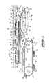
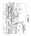
- Fig. 1 shows a device through which a carcass part passes from the righthand side to the lefthand side.
- the carcass part is moved along, hanging by the legs on a conveyor 2, in the direction of arrow 4 by means of double hooks 6 which are connected to a drive chain at regular intervals from each other.
- the design of such a conveyor unit is known per se and is not explained any further here. What is important is that from the end of a leg conveyance guide strip 7 the conveyor 2 can no longer hold the legs in the outward direction.
- two leg guide bars 8 are disposed symmetrically relative to the vertical central longitudinal plane of the device, and in the direction of conveyance 4 diverge sideways and run downwards. Their purpose is to go between the legs hanging next to each other and press them sideways on the inside of each leg away from each other.
- two leg push-out strips 10 are fixed symmetrically relative to the central longitudinal plane of the device by means of bolts 12 on a frame 14 bearing the parts of the device.
- bolts 12 On a frame 14 bearing the parts of the device.
- large parts of the frame are not shown in this figure and the figures following, but it goes without saying that all parts are supported at suitable places in a suitable manner by the frame, or are mounted in the frame.
- the leg guide bars 8 Disposed below the leg guide bars 8 are two parallel endless plate chains which are a mirror image of each other relative to the above-mentioned central longitudinal plane of the device.
- the plate chain 16 shown in Fig. 1 is constructed of plates 18 which are coupled to each other at right angles to the plane of drawing, and which are flanged at an acute angle.
- the two plate chains thus together form an essentially V-shaped channel below the conveyor 2 and moving along with it when they are driven by means of a sprocket wheel 20 and move via a track wheel 22 in the direction of the arrow 24 over a guide 26.
- an endless spiked chain 30 which can move in the direction of the arrow 32 around two sprocket wheels, of which only sprocket wheel 33 is visible and is driven.
- the spiked chain 30 runs above a guide face formed by the top face of a body guide bar 34.
- the bottom side of the spiked chain 30 begins above a virtually horizontal part of the plate chain 16 and also at a point which, viewed in the direction of conveyance 4, lies just before the end of the leg conveyance guide strip 7.
- two groin incision cutters 28 are disposed between the leg push-out strips 10, symmetrically relative to the central longitudinal plane.
- leg guide bars 8 are bent downwards lies the beginning of joint ball guide strips 36, which are initially also bent downwards, but otherwise run horizontally.
- Each caudal incision cutter 38 is pivotable about a pin 39, and the cutting edge of said cutter is pressed in the direction of the central longitudinal plane by a spring which is not shown.
- Each back incision cutter 40 is pivotable about a pin 41, and the cutting edge of said cutter is pressed in the direction of the spiked chain by a spring which is not shown. Further details of the cutters 38 and 40 are shown below in and discussed with reference to Fig. 8.
- a second endless spiked chain 42 is disposed above the body guide bar 34, in line with spiked chain 30 and with some space between them.
- the spiked chain 42 also rotates over two sprocket wheels 44 and 46, one of which drives the chain in the direction of arrow 48.
- a second plate chain 50 on which plates 52 are fixed at regular intervals, is disposed below the body guide bar 34 and the spiked chain 42 in the central longitudinal plane of the device.
- Each plate 52 is provided, at the edge facing the direction of movement 54 of the plate chain 50, with two V-shaped recesses 56, the purpose of which is to grip the legs of the carcass part to be processed by the device.
- the movement of the plate chain 50 can be obtained by driving one of the two sprocket wheels 58 and 60 over which the plate chain runs.
- a bent plate 62 with a V-shaped cross-section is provided, which plate serves as a discharge plate for body parts from which the legs have been separated.
- the parts of the device are provided with adjusting devices to permit adjustment to the dimensions.
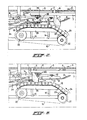
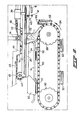
- a carcass part 1, hanging by the legs from a double hook 6, is moved along a conveyor 2 by means of a conveyor chain 5 coupled to the hooks 6.
- the legs of the carcass part 1, which is shown in side view, are here pressed outwards by the leg guide bars 8 and leg push-out strips 10, which are formed in such a way that they go on the inside of the legs during the conveyance.
- the carcass part 1 is moved along, both by the hook 6 at the tarsal joints, and by the plate chain 16 at the back part.
- the carcass part 1 comes up against an upward sloping edge of body guide bar 34 which takes the body part of the carcass part to the required height.
- the horizontal speed of the plate chain 16 is almost the same as that of hook 6, which makes the carcass part 1 land in a desired position at the beginning of the spiked chain 30. This situation is shown in Fig. 3.
- Fig. 4 shows in detail how a groin incision cutter 28 in the position of the carcass part 1 shown in Fig. 3 cuts through skin and tendons between a leg and the body part; the cutting edge of the cutter 28 coincides with the dashed line.
- the leg push-out strips 10 together with the body guide bar 34 and the plate chain 16 exert such a force on the legs near the hip joint ball that the hip joints are dislocated, in other words, the hip joint ball on the end of the thigh bone is pressed out of the hip joint socket in the body part.
- leg guide bars 8 bend the legs further outwards, with the result that the hip joint balls 70 project out of the meat.
- the legs are pointing downwards at this processing stage.
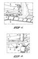
- the hip joint balls 70 subsequently come to rest under the joint ball guide strips 36, as shown in Fig. 6.
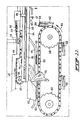
- the downward running joint ball guide strips 36 press the hip joint balls downwards and thus cause the legs to finish up hanging in a virtually vertical position. In this position, which is shown in Fig. 7, the carcass part passes the caudal incision cutters 38 and the back incision cutters 40.
- the caudal incision cutters 38 the cutting edge of which is situated at the side of the spiked chain 30, thanks to the action of the joint ball guide strips 36 on the hip joint balls 70, cut past the dislocated hip joint through tendons between each leg and the body part.
- the back incision cutters 40 the cutting edge of which is also at the side of the spiked chain 30, cut through skin and membranes on either side of the crest-shaped thickened part on the rear side of the body part, which thickened part is centred relative to the cutters 40 by a groove (not shown) in the top side of the body guide bar 34. It is also possible to adjust the cutting depth of the cutters 40 by means of a movable block 43 fitted between the cutters 40. Of course, the body guide bar 34 is interrupted at the position of the cutters 40.
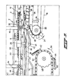
- the body part After pulling off of the legs, the body part is conveyed further by the spiked chain 42 until it arrives on the discharge plate 62, after which it leaves the device for further processing.
- the detached legs fall out of the recesses 56 on movement of the plate 52 around the sprocket wheel 60, following which they are collected outside the device and are processed further.
- Fig. 12 shows the way in which the links of the spiked chains 30 and 42 are formed.
- Plates 72 are fixed between the spikes of the outside links, at right angles to the lengthwise direction of the chain. When the body part of a carcass part moves forward, the plates 72 go between the protuberances on the inside of the body part in line with the backbone of the bird. The plates 72 thus ensure a slip-free forward driving or braking of the body part over the body guide bar 34 by means of the spiked chains 30 and 42, respectively.
Landscapes
- Life Sciences & Earth Sciences (AREA)
- Engineering & Computer Science (AREA)
- Wood Science & Technology (AREA)
- Zoology (AREA)
- Food Science & Technology (AREA)
- Processing Of Meat And Fish (AREA)
- Prostheses (AREA)
Applications Claiming Priority (2)
| Application Number | Priority Date | Filing Date | Title |
|---|---|---|---|
| NL9001246A NL9001246A (nl) | 1990-05-31 | 1990-05-31 | Werkwijze en inrichting voor het van een rompdeel scheiden van de poten van geslacht gevogelte. |
| NL9001246 | 1990-05-31 |
Publications (2)
| Publication Number | Publication Date |
|---|---|
| EP0459580A1 true EP0459580A1 (de) | 1991-12-04 |
| EP0459580B1 EP0459580B1 (de) | 1995-08-23 |
Family
ID=19857175
Family Applications (1)
| Application Number | Title | Priority Date | Filing Date |
|---|---|---|---|
| EP91201256A Expired - Lifetime EP0459580B1 (de) | 1990-05-31 | 1991-05-24 | Verfahren und Vorrichtung zum Abtrennen der Beine von Schlachtgeflügel-Körperstücken |
Country Status (7)
| Country | Link |
|---|---|
| US (1) | US5176563A (de) |
| EP (1) | EP0459580B1 (de) |
| JP (1) | JP3379967B2 (de) |
| DE (1) | DE69112280T2 (de) |
| DK (1) | DK0459580T3 (de) |
| ES (1) | ES2077789T3 (de) |
| NL (1) | NL9001246A (de) |
Cited By (10)
| Publication number | Priority date | Publication date | Assignee | Title |
|---|---|---|---|---|
| EP0551156A1 (de) * | 1992-01-10 | 1993-07-14 | Stork Pmt B.V. | Verfahren und Vorrichtung zum Filetieren des Körpers von Schlachtgeflügel |
| EP0720817A1 (de) * | 1995-01-03 | 1996-07-10 | Nordischer Maschinenbau Rud. Baader Gmbh + Co Kg | Einrichtung zum Zerlegen der Flügel von Geflügelkörper |
| EP0853884A1 (de) * | 1997-01-21 | 1998-07-22 | Nordischer Maschinenbau Rud. Baader Gmbh + Co Kg | Einrichtung zum Bearbeiten von Geflügelkörpern |
| US6004199A (en) * | 1997-01-21 | 1999-12-21 | Nordischer Maschinenbau Rud. Baader Gmbh & Co. Kg | Apparatus and method for separating legs from poultry carcasses |
| US7824251B2 (en) | 2002-12-20 | 2010-11-02 | Stork Pmt B.V. | Method and device for processing a carcass part of a slaughtered poultry |
| NL2009646C2 (en) * | 2012-10-17 | 2014-04-22 | Marel Stork Poultry Proc Bv | System and method for harvesting saddle meat from a carcass part of slaughtered poultry. |
| NL2009647C2 (en) * | 2012-10-17 | 2014-04-22 | Marel Stork Poultry Proc Bv | Device for separating a leg part from a carcass part of slaughtered poultry. |
| EP2936988A1 (de) * | 2014-04-24 | 2015-10-28 | Meyn Food Processing Technology B.V. | Geflügelverarbeitungsvorrichtung |
| CN105522611A (zh) * | 2016-01-29 | 2016-04-27 | 罗文锋 | 一种切片切条机 |
| US9801394B2 (en) | 2015-10-22 | 2017-10-31 | Baader Linco, Inc. | Separation tool |
Families Citing this family (30)
| Publication number | Priority date | Publication date | Assignee | Title |
|---|---|---|---|---|
| NL9101050A (nl) * | 1991-06-18 | 1993-01-18 | Stork Pmt | Werkwijze en inrichting voor het bewerken van de huid van een poot van een geslachte vogel. |
| US5766064A (en) * | 1997-03-03 | 1998-06-16 | Gasbarro; Geno N. | Method and apparatus for scoring poultry hocks |
| US5947811A (en) * | 1997-04-10 | 1999-09-07 | Systemate Holland, B.V. | Apparatus for cutting up carcasses of poultry |
| US6195206B1 (en) | 1998-01-13 | 2001-02-27 | Elbit Systems Ltd. | Optical system for day and night use |
| NL1010558C2 (nl) * | 1998-11-16 | 2000-05-17 | Meyn Maschf | Werkwijze en inrichting voor het uniform positioneren van poten van geslacht gevogelte. |
| JP4367952B2 (ja) | 2003-06-20 | 2009-11-18 | 株式会社前川製作所 | 腿肉とオイスタミートの分離方法とその装置 |
| NL1034027C2 (nl) | 2007-06-22 | 2008-12-23 | Stork Pmt | Inrichting en werkwijze voor het in positie brengen en het aanbrengen van een borstkap van een geslacht gevogelte op een productdrager. |
| US8632380B2 (en) * | 2010-01-26 | 2014-01-21 | Foodmate B.V. | Method and apparatus for removing a sleeve of meat from an animal part having bone with knuckles on each of its opposite ends |
| US8157625B2 (en) | 2010-01-26 | 2012-04-17 | Foodmate Bv | Method and apparatus for collecting meat from an animal part |
| NL2006075C2 (en) | 2011-01-26 | 2012-07-30 | Foodmate B V | Rotationally indexed article support for a conveyor system having an alignment station. |
| NL2004573C2 (en) | 2010-04-19 | 2011-10-20 | Foodmate B V | Turning block alignment. |
| US8757354B2 (en) | 2010-04-19 | 2014-06-24 | Foodmate Bv | Turning block alignment |
| NL2004574C2 (en) | 2010-04-19 | 2011-10-20 | Foodmate B V | Rotatable article support for a conveyor. |
| US8789684B2 (en) | 2010-04-19 | 2014-07-29 | Foodmate Bv | Rotatable article support for a conveyor |
| US8727839B2 (en) | 2011-01-21 | 2014-05-20 | Foodmate Bv | Poultry wing cutter for narrow pitch poultry lines |
| PL2667728T3 (pl) | 2011-01-26 | 2016-01-29 | Foodmate Bv | Sposób usuwania kości z ud zwierzęcych w celu oddzielania i zbierania z nich mięsa oraz urządzenie realizujące sposób |
| US8882571B2 (en) | 2011-01-26 | 2014-11-11 | Foodmate Bv | Method of deboning animal thighs for separating and collecting meat therefrom and apparatus for performing the method |
| US8267241B2 (en) | 2011-01-26 | 2012-09-18 | Foodmate Bv | Rotationally indexed article support for a conveyor system having an alignment station |
| US8430728B2 (en) | 2011-02-14 | 2013-04-30 | Foodmate Bv | Special cut poultry wing cutter |
| NL2008021C2 (en) | 2011-12-22 | 2013-06-26 | Meyn Food Proc Technology Bv | Method and device for processing a carcass part of slaughtered poultry. |
| NL2008729C2 (en) | 2012-04-27 | 2013-10-29 | Meyn Food Proc Technology Bv | A method and apparatus for processing a poultry carcass part. |
| US8500523B1 (en) | 2012-06-07 | 2013-08-06 | Marel Meat Processing Inc. | Cutting system and method of cutting meat parts using the same |
| NL2009033C2 (en) | 2012-06-19 | 2013-12-23 | Foodmate B V | Weighing method and apparatus. |
| US9066525B2 (en) | 2012-07-12 | 2015-06-30 | Marel Meat Processing Inc. | Shoulder positioning conveyor |
| NL2009718C2 (en) | 2012-10-29 | 2014-05-01 | Foodmate B V | Method of mechanically removing skin from animal parts. |
| US8808068B2 (en) | 2012-10-29 | 2014-08-19 | Foodmate Bv | Method of and system for automatically removing meat from an animal extremity |
| NL2009782C2 (en) * | 2012-11-09 | 2014-05-12 | Marel Stork Poultry Proc Bv | Device and method for processing carcass parts of slaughtered poultry. |
| US9078453B2 (en) | 2013-11-01 | 2015-07-14 | Foodmate B.V. | Method and system for automatically deboning poultry breast caps containing meat and a skeletal structure to obtain breast fillets therefrom |
| US8961274B1 (en) | 2013-12-18 | 2015-02-24 | Foodmate Bv | Selective tendon cutter and method |
| NL2028710B1 (en) * | 2021-07-13 | 2023-01-18 | Marel Poultry B V | System and method for processing a carcass part |
Citations (8)
| Publication number | Priority date | Publication date | Assignee | Title |
|---|---|---|---|---|
| US4016624A (en) * | 1975-10-17 | 1977-04-12 | Victor F. Weaver, Inc. | Poultry cut-up machine |
| US4102014A (en) * | 1977-04-04 | 1978-07-25 | Victor F. Weaver, Inc. | Modification assembly to a machine for processing the backs of poultry |
| US4271561A (en) * | 1979-09-11 | 1981-06-09 | Lewis Eugene J | Poultry dismembering apparatus |
| US4385421A (en) * | 1981-05-20 | 1983-05-31 | Victor F. Weaver, Inc. | Poultry leg/back processor |
| US4480353A (en) * | 1983-03-28 | 1984-11-06 | Foodcraft Equipment Co., Inc. | Leg splitting machine |
| NL8303683A (nl) * | 1983-10-26 | 1985-05-17 | Meyn Pieter | Inrichting voor het scheiden van de poten en het rugstuk van geslachte vogels. |
| EP0369544A1 (de) * | 1988-11-14 | 1990-05-23 | Systemate Holland B.V. | Vorrichtung zum Abtrennen der Beine von Schlachtgeflügel-Rückenstücken |
| US4993115A (en) * | 1989-12-08 | 1991-02-19 | Hazenbroek Jacobus E | Compact wing cut-off machine |
Family Cites Families (1)
| Publication number | Priority date | Publication date | Assignee | Title |
|---|---|---|---|---|
| EP0390979A1 (de) * | 1989-04-07 | 1990-10-10 | Linco Holland Engineering B.V. | Methode und Vorrichtung zum Transportieren von Gegenständen auf einer Bahn mit geschlossenem Umlauf |
-
1990
- 1990-05-31 NL NL9001246A patent/NL9001246A/nl not_active Application Discontinuation
-
1991
- 1991-05-24 ES ES91201256T patent/ES2077789T3/es not_active Expired - Lifetime
- 1991-05-24 DE DE69112280T patent/DE69112280T2/de not_active Expired - Fee Related
- 1991-05-24 DK DK91201256.4T patent/DK0459580T3/da active
- 1991-05-24 EP EP91201256A patent/EP0459580B1/de not_active Expired - Lifetime
- 1991-05-30 US US07/707,678 patent/US5176563A/en not_active Expired - Lifetime
- 1991-05-30 JP JP12784791A patent/JP3379967B2/ja not_active Expired - Lifetime
Patent Citations (8)
| Publication number | Priority date | Publication date | Assignee | Title |
|---|---|---|---|---|
| US4016624A (en) * | 1975-10-17 | 1977-04-12 | Victor F. Weaver, Inc. | Poultry cut-up machine |
| US4102014A (en) * | 1977-04-04 | 1978-07-25 | Victor F. Weaver, Inc. | Modification assembly to a machine for processing the backs of poultry |
| US4271561A (en) * | 1979-09-11 | 1981-06-09 | Lewis Eugene J | Poultry dismembering apparatus |
| US4385421A (en) * | 1981-05-20 | 1983-05-31 | Victor F. Weaver, Inc. | Poultry leg/back processor |
| US4480353A (en) * | 1983-03-28 | 1984-11-06 | Foodcraft Equipment Co., Inc. | Leg splitting machine |
| NL8303683A (nl) * | 1983-10-26 | 1985-05-17 | Meyn Pieter | Inrichting voor het scheiden van de poten en het rugstuk van geslachte vogels. |
| EP0369544A1 (de) * | 1988-11-14 | 1990-05-23 | Systemate Holland B.V. | Vorrichtung zum Abtrennen der Beine von Schlachtgeflügel-Rückenstücken |
| US4993115A (en) * | 1989-12-08 | 1991-02-19 | Hazenbroek Jacobus E | Compact wing cut-off machine |
Cited By (20)
| Publication number | Priority date | Publication date | Assignee | Title |
|---|---|---|---|---|
| EP0551156A1 (de) * | 1992-01-10 | 1993-07-14 | Stork Pmt B.V. | Verfahren und Vorrichtung zum Filetieren des Körpers von Schlachtgeflügel |
| US5312291A (en) * | 1992-01-10 | 1994-05-17 | Stork Pmt B.V. | Method and device for filleting the body of a slaughtered bird |
| EP0720817A1 (de) * | 1995-01-03 | 1996-07-10 | Nordischer Maschinenbau Rud. Baader Gmbh + Co Kg | Einrichtung zum Zerlegen der Flügel von Geflügelkörper |
| EP0853884A1 (de) * | 1997-01-21 | 1998-07-22 | Nordischer Maschinenbau Rud. Baader Gmbh + Co Kg | Einrichtung zum Bearbeiten von Geflügelkörpern |
| US6004199A (en) * | 1997-01-21 | 1999-12-21 | Nordischer Maschinenbau Rud. Baader Gmbh & Co. Kg | Apparatus and method for separating legs from poultry carcasses |
| US7824251B2 (en) | 2002-12-20 | 2010-11-02 | Stork Pmt B.V. | Method and device for processing a carcass part of a slaughtered poultry |
| US9375020B2 (en) | 2012-10-17 | 2016-06-28 | Marel Stork Poultry Processing B.V. | Device for separating a leg part from a carcass part of slaughtered poultry |
| US9375019B2 (en) | 2012-10-17 | 2016-06-28 | Marel Stork Poultry Processing B.V. | System and method for harvesting saddle meat from a carcass part of slaughtered poultry |
| WO2014062054A1 (en) | 2012-10-17 | 2014-04-24 | Marel Stork Poultry Processing B.V. | Device for separating a leg part from a carcass part of slaughtered poultry |
| WO2014062053A1 (en) | 2012-10-17 | 2014-04-24 | Marel Stork Poultry Processing B.V. | System and method for harvesting saddle meat from a carcass part of slaughtered poultry |
| NL2009647C2 (en) * | 2012-10-17 | 2014-04-22 | Marel Stork Poultry Proc Bv | Device for separating a leg part from a carcass part of slaughtered poultry. |
| NL2009646C2 (en) * | 2012-10-17 | 2014-04-22 | Marel Stork Poultry Proc Bv | System and method for harvesting saddle meat from a carcass part of slaughtered poultry. |
| US9320287B2 (en) | 2012-10-17 | 2016-04-26 | Marel Stork Poultry Processing B.V. | System and method for harvesting saddle meat from a carcass part of slaughtered poultry |
| RU2590774C1 (ru) * | 2014-04-24 | 2016-07-10 | Мейн Фуд Просессинг Текнолоджи Б.В. | Устройство для разделки птицы и способ отделения ножек |
| NL2012678A (en) * | 2014-04-24 | 2016-02-04 | Meyn Food Proc Technology Bv | Poultry processing apparatus. |
| EP2936988A1 (de) * | 2014-04-24 | 2015-10-28 | Meyn Food Processing Technology B.V. | Geflügelverarbeitungsvorrichtung |
| US9801394B2 (en) | 2015-10-22 | 2017-10-31 | Baader Linco, Inc. | Separation tool |
| US10165783B2 (en) | 2015-10-22 | 2019-01-01 | Baader Linco, Inc. | Poultry carcass processing method |
| CN105522611A (zh) * | 2016-01-29 | 2016-04-27 | 罗文锋 | 一种切片切条机 |
| CN105522611B (zh) * | 2016-01-29 | 2017-11-10 | 福建天天见食品有限公司 | 一种切片切条机 |
Also Published As
| Publication number | Publication date |
|---|---|
| NL9001246A (nl) | 1991-12-16 |
| ES2077789T3 (es) | 1995-12-01 |
| DE69112280D1 (de) | 1995-09-28 |
| JPH04228022A (ja) | 1992-08-18 |
| EP0459580B1 (de) | 1995-08-23 |
| DE69112280T2 (de) | 1996-04-04 |
| DK0459580T3 (da) | 1996-01-15 |
| JP3379967B2 (ja) | 2003-02-24 |
| US5176563A (en) | 1993-01-05 |
Similar Documents
| Publication | Publication Date | Title |
|---|---|---|
| US5176563A (en) | Method and device for separating the legs from a body part of slaughtered poultry | |
| US5035673A (en) | On-line breast halver | |
| EP0054060B1 (de) | Geflügelschneidevorrichtung | |
| US5019013A (en) | On line breast halver and processor | |
| US4648156A (en) | Method and apparatus for removing the breast flesh from a poultry carcass | |
| US6095914A (en) | Device and method for processing a slaughtered animal | |
| US5015213A (en) | On-line cut-up system with joint opener | |
| US20080171506A1 (en) | Processing of Carcass Parts of Slaughtered Poultry | |
| EP0512636B1 (de) | Verfahren und Vorrichtung zum mechanischem Ausnehmen von Schlachtgeflügel | |
| US4639975A (en) | Device for separating the legs from a carcass portion of slaughtered poultry | |
| US4557017A (en) | Apparatus for filleting meat from poultry breast sections | |
| EP0552421A1 (de) | Verfahren und Vorrichtung zum kontinuierlichen Abtrennen der Beine von Schlachtgeflügel | |
| US4648155A (en) | Chicken deboning apparatus and method | |
| SU1667618A3 (ru) | Способ отделени крыльев от тушек птицы и устройство дл его осуществлени | |
| US6749497B2 (en) | Apparatus and method of edible feet harvest and paw production | |
| US5083972A (en) | Method and apparatus for decapitating and eviscerating fish | |
| US4574427A (en) | Neck pulling and cropping system | |
| US3793676A (en) | Method and apparatus for removing roe and viscera from a fish | |
| US5083974A (en) | Turkey breast deboner | |
| US5954574A (en) | Wing remover | |
| US5472377A (en) | Poultry processing method, apparatus, and product | |
| EP0784932B1 (de) | Flügel-Entferner | |
| JPH0793863B2 (ja) | バックプラー | |
| CA2443445A1 (en) | A device for skinning poultry parts | |
| JPH0793861B2 (ja) | 屠体処理装置のレッグプロセッサー |
Legal Events
| Date | Code | Title | Description |
|---|---|---|---|
| PUAI | Public reference made under article 153(3) epc to a published international application that has entered the european phase |
Free format text: ORIGINAL CODE: 0009012 |
|
| AK | Designated contracting states |
Kind code of ref document: A1 Designated state(s): DE DK ES FR GB IT NL |
|
| 17P | Request for examination filed |
Effective date: 19920511 |
|
| 17Q | First examination report despatched |
Effective date: 19930316 |
|
| GRAA | (expected) grant |
Free format text: ORIGINAL CODE: 0009210 |
|
| AK | Designated contracting states |
Kind code of ref document: B1 Designated state(s): DE DK ES FR GB IT NL |
|
| ITF | It: translation for a ep patent filed |
Owner name: BARZANO' E ZANARDO ROMA S.P.A. |
|
| REF | Corresponds to: |
Ref document number: 69112280 Country of ref document: DE Date of ref document: 19950928 |
|
| ET | Fr: translation filed | ||
| REG | Reference to a national code |
Ref country code: ES Ref legal event code: FG2A Ref document number: 2077789 Country of ref document: ES Kind code of ref document: T3 |
|
| REG | Reference to a national code |
Ref country code: DK Ref legal event code: T3 |
|
| PLBE | No opposition filed within time limit |
Free format text: ORIGINAL CODE: 0009261 |
|
| STAA | Information on the status of an ep patent application or granted ep patent |
Free format text: STATUS: NO OPPOSITION FILED WITHIN TIME LIMIT |
|
| 26N | No opposition filed | ||
| REG | Reference to a national code |
Ref country code: GB Ref legal event code: IF02 |
|
| PGFP | Annual fee paid to national office [announced via postgrant information from national office to epo] |
Ref country code: GB Payment date: 20060425 Year of fee payment: 16 |
|
| PGFP | Annual fee paid to national office [announced via postgrant information from national office to epo] |
Ref country code: ES Payment date: 20060522 Year of fee payment: 16 |
|
| PGFP | Annual fee paid to national office [announced via postgrant information from national office to epo] |
Ref country code: FR Payment date: 20060530 Year of fee payment: 16 |
|
| PGFP | Annual fee paid to national office [announced via postgrant information from national office to epo] |
Ref country code: IT Payment date: 20060531 Year of fee payment: 16 |
|
| GBPC | Gb: european patent ceased through non-payment of renewal fee |
Effective date: 20070524 |
|
| REG | Reference to a national code |
Ref country code: FR Ref legal event code: ST Effective date: 20080131 |
|
| PG25 | Lapsed in a contracting state [announced via postgrant information from national office to epo] |
Ref country code: GB Free format text: LAPSE BECAUSE OF NON-PAYMENT OF DUE FEES Effective date: 20070524 |
|
| PG25 | Lapsed in a contracting state [announced via postgrant information from national office to epo] |
Ref country code: FR Free format text: LAPSE BECAUSE OF NON-PAYMENT OF DUE FEES Effective date: 20070531 |
|
| PGFP | Annual fee paid to national office [announced via postgrant information from national office to epo] |
Ref country code: DE Payment date: 20080527 Year of fee payment: 18 Ref country code: DK Payment date: 20080526 Year of fee payment: 18 |
|
| REG | Reference to a national code |
Ref country code: ES Ref legal event code: FD2A Effective date: 20070525 |
|
| PG25 | Lapsed in a contracting state [announced via postgrant information from national office to epo] |
Ref country code: ES Free format text: LAPSE BECAUSE OF NON-PAYMENT OF DUE FEES Effective date: 20070525 |
|
| PG25 | Lapsed in a contracting state [announced via postgrant information from national office to epo] |
Ref country code: IT Free format text: LAPSE BECAUSE OF NON-PAYMENT OF DUE FEES Effective date: 20070524 |
|
| REG | Reference to a national code |
Ref country code: DK Ref legal event code: EBP |
|
| PG25 | Lapsed in a contracting state [announced via postgrant information from national office to epo] |
Ref country code: DK Free format text: LAPSE BECAUSE OF NON-PAYMENT OF DUE FEES Effective date: 20090531 |
|
| PG25 | Lapsed in a contracting state [announced via postgrant information from national office to epo] |
Ref country code: DE Free format text: LAPSE BECAUSE OF NON-PAYMENT OF DUE FEES Effective date: 20091201 |
|
| PGFP | Annual fee paid to national office [announced via postgrant information from national office to epo] |
Ref country code: NL Payment date: 20100527 Year of fee payment: 20 |
|
| REG | Reference to a national code |
Ref country code: NL Ref legal event code: V4 Effective date: 20110524 |
|
| PG25 | Lapsed in a contracting state [announced via postgrant information from national office to epo] |
Ref country code: NL Free format text: LAPSE BECAUSE OF EXPIRATION OF PROTECTION Effective date: 20110524 |