EP0459534B1 - Monolith- bzw. wabenförmiger Katalysator - Google Patents
Monolith- bzw. wabenförmiger Katalysator Download PDFInfo
- Publication number
- EP0459534B1 EP0459534B1 EP91113441A EP91113441A EP0459534B1 EP 0459534 B1 EP0459534 B1 EP 0459534B1 EP 91113441 A EP91113441 A EP 91113441A EP 91113441 A EP91113441 A EP 91113441A EP 0459534 B1 EP0459534 B1 EP 0459534B1
- Authority
- EP
- European Patent Office
- Prior art keywords
- catalyst
- monolith
- honeycomb body
- honeycomb
- metal oxide
- Prior art date
- Legal status (The legal status is an assumption and is not a legal conclusion. Google has not performed a legal analysis and makes no representation as to the accuracy of the status listed.)
- Expired - Lifetime
Links
Images
Classifications
-
- B—PERFORMING OPERATIONS; TRANSPORTING
- B01—PHYSICAL OR CHEMICAL PROCESSES OR APPARATUS IN GENERAL
- B01J—CHEMICAL OR PHYSICAL PROCESSES, e.g. CATALYSIS OR COLLOID CHEMISTRY; THEIR RELEVANT APPARATUS
- B01J35/00—Catalysts, in general, characterised by their form or physical properties
- B01J35/50—Catalysts, in general, characterised by their form or physical properties characterised by their shape or configuration
- B01J35/56—Foraminous structures having flow-through passages or channels, e.g. grids or three-dimensional [3D] monoliths
- B01J35/57—Honeycombs
-
- B—PERFORMING OPERATIONS; TRANSPORTING
- B01—PHYSICAL OR CHEMICAL PROCESSES OR APPARATUS IN GENERAL
- B01D—SEPARATION
- B01D53/00—Separation of gases or vapours; Recovering vapours of volatile solvents from gases; Chemical or biological purification of waste gases, e.g. engine exhaust gases, smoke, fumes, flue gases, aerosols
- B01D53/34—Chemical or biological purification of waste gases
- B01D53/92—Chemical or biological purification of waste gases of engine exhaust gases
- B01D53/94—Chemical or biological purification of waste gases of engine exhaust gases by catalytic processes
- B01D53/9445—Simultaneously removing carbon monoxide, hydrocarbons or nitrogen oxides making use of three-way catalysts [TWC] or four-way-catalysts [FWC]
- B01D53/945—Simultaneously removing carbon monoxide, hydrocarbons or nitrogen oxides making use of three-way catalysts [TWC] or four-way-catalysts [FWC] characterised by a specific catalyst
-
- B—PERFORMING OPERATIONS; TRANSPORTING
- B01—PHYSICAL OR CHEMICAL PROCESSES OR APPARATUS IN GENERAL
- B01J—CHEMICAL OR PHYSICAL PROCESSES, e.g. CATALYSIS OR COLLOID CHEMISTRY; THEIR RELEVANT APPARATUS
- B01J35/00—Catalysts, in general, characterised by their form or physical properties
- B01J35/19—Catalysts containing parts with different compositions
-
- B—PERFORMING OPERATIONS; TRANSPORTING
- B01—PHYSICAL OR CHEMICAL PROCESSES OR APPARATUS IN GENERAL
- B01J—CHEMICAL OR PHYSICAL PROCESSES, e.g. CATALYSIS OR COLLOID CHEMISTRY; THEIR RELEVANT APPARATUS
- B01J35/00—Catalysts, in general, characterised by their form or physical properties
- B01J35/30—Catalysts, in general, characterised by their form or physical properties characterised by their physical properties
- B01J35/396—Distribution of the active metal ingredient
-
- B—PERFORMING OPERATIONS; TRANSPORTING
- B01—PHYSICAL OR CHEMICAL PROCESSES OR APPARATUS IN GENERAL
- B01J—CHEMICAL OR PHYSICAL PROCESSES, e.g. CATALYSIS OR COLLOID CHEMISTRY; THEIR RELEVANT APPARATUS
- B01J37/00—Processes, in general, for preparing catalysts; Processes, in general, for activation of catalysts
- B01J37/02—Impregnation, coating or precipitation
- B01J37/024—Multiple impregnation or coating
- B01J37/0242—Coating followed by impregnation
-
- F—MECHANICAL ENGINEERING; LIGHTING; HEATING; WEAPONS; BLASTING
- F01—MACHINES OR ENGINES IN GENERAL; ENGINE PLANTS IN GENERAL; STEAM ENGINES
- F01N—GAS-FLOW SILENCERS OR EXHAUST APPARATUS FOR MACHINES OR ENGINES IN GENERAL; GAS-FLOW SILENCERS OR EXHAUST APPARATUS FOR INTERNAL-COMBUSTION ENGINES
- F01N3/00—Exhaust or silencing apparatus having means for purifying, rendering innocuous, or otherwise treating exhaust
- F01N3/08—Exhaust or silencing apparatus having means for purifying, rendering innocuous, or otherwise treating exhaust for rendering innocuous
- F01N3/10—Exhaust or silencing apparatus having means for purifying, rendering innocuous, or otherwise treating exhaust for rendering innocuous by thermal or catalytic conversion of noxious components of exhaust
- F01N3/24—Exhaust or silencing apparatus having means for purifying, rendering innocuous, or otherwise treating exhaust for rendering innocuous by thermal or catalytic conversion of noxious components of exhaust characterised by constructional aspects of converting apparatus
- F01N3/28—Construction of catalytic reactors
- F01N3/2803—Construction of catalytic reactors characterised by structure, by material or by manufacturing of catalyst support
-
- F—MECHANICAL ENGINEERING; LIGHTING; HEATING; WEAPONS; BLASTING
- F01—MACHINES OR ENGINES IN GENERAL; ENGINE PLANTS IN GENERAL; STEAM ENGINES
- F01N—GAS-FLOW SILENCERS OR EXHAUST APPARATUS FOR MACHINES OR ENGINES IN GENERAL; GAS-FLOW SILENCERS OR EXHAUST APPARATUS FOR INTERNAL-COMBUSTION ENGINES
- F01N2330/00—Structure of catalyst support or particle filter
- F01N2330/02—Metallic plates or honeycombs, e.g. superposed or rolled-up corrugated or otherwise deformed sheet metal
- F01N2330/04—Methods of manufacturing
-
- F—MECHANICAL ENGINEERING; LIGHTING; HEATING; WEAPONS; BLASTING
- F01—MACHINES OR ENGINES IN GENERAL; ENGINE PLANTS IN GENERAL; STEAM ENGINES
- F01N—GAS-FLOW SILENCERS OR EXHAUST APPARATUS FOR MACHINES OR ENGINES IN GENERAL; GAS-FLOW SILENCERS OR EXHAUST APPARATUS FOR INTERNAL-COMBUSTION ENGINES
- F01N2560/00—Exhaust systems with means for detecting or measuring exhaust gas components or characteristics
- F01N2560/08—Exhaust systems with means for detecting or measuring exhaust gas components or characteristics the means being a pressure sensor
-
- Y—GENERAL TAGGING OF NEW TECHNOLOGICAL DEVELOPMENTS; GENERAL TAGGING OF CROSS-SECTIONAL TECHNOLOGIES SPANNING OVER SEVERAL SECTIONS OF THE IPC; TECHNICAL SUBJECTS COVERED BY FORMER USPC CROSS-REFERENCE ART COLLECTIONS [XRACs] AND DIGESTS
- Y02—TECHNOLOGIES OR APPLICATIONS FOR MITIGATION OR ADAPTATION AGAINST CLIMATE CHANGE
- Y02T—CLIMATE CHANGE MITIGATION TECHNOLOGIES RELATED TO TRANSPORTATION
- Y02T10/00—Road transport of goods or passengers
- Y02T10/10—Internal combustion engine [ICE] based vehicles
- Y02T10/12—Improving ICE efficiencies
Definitions
- the invention relates to a monolithic or honeycomb-shaped catalyst, in particular for cleaning the exhaust gases of internal combustion engines, from an inert ceramic or metallic carrier with parallel flow channels, a layer of catalyst-promoting metal oxide arranged thereon and a catalytically active component carried by the metal oxide.
- the catalyst has improved light-off behavior.
- An important property of monolith or honeycomb type catalysts is the speed at which the catalyst reaches operating temperature when exposed to a hot gas to be treated.
- the use of such catalysts as chemical catalysts or exhaust gas purification catalysts. e.g. B. for industrial exhaust or engine exhaust can be simplified significantly by improving this property.
- the invention opens up a new way of solving the problem.
- the invention relates to a monolithic or honeycomb-shaped catalyst, in particular for cleaning the exhaust gases of internal combustion engines, from an inert ceramic or metallic carrier with parallel flow channels, a layer of catalyst-promoting metal oxide arranged thereon and a catalytically active component carried by the metal oxide, which characterized in that the catalyst-promoting metal oxide is substantially uniformly distributed between the central axis and the periphery of the carrier and the concentration of the catalytically active component increases from the central axis to the periphery of the carrier.
- a concentration distribution of the catalytically active component according to the invention results in a more balanced heat development when starting and running exothermic reactions by the effect of the natural speed profile when monoliths or honeycombs flow through, or even empty pipes through gases, which is more pronounced around the central axis than at the edge zones , is balanced.
- the monolith or honeycomb catalyst according to the invention can, for. B. can be used in cases in which the flow paths leading to the catalyst have the same cross-section as the monolith or the honeycomb, that is to say there is a more uniform gas exposure to the flow surface from the start.
- the noble metal concentration rising from the central axis to the periphery counteracts a reduction in the conversion in the outer monolith or honeycomb regions as a result of cooling of the pollutant converter in which the monolith or honeycomb is located, due to airflow.
- the concentration profile to be used according to the invention for the loading with catalytically active component, which is to be developed in stages or continuously, can be, for. B. gradually adjust by an end face during the loading in several stages through a mask covering the center or the edge area, z. B. in the form of a disc or a ring, kept free of the respective order and the remaining free area is loaded one or more times with the substance to be applied according to the desired concentration.
- a continuous loading of the catalytically active component can be achieved by means of a slat arrangement which opens or closes continuously in the manner of a photo central lock, and is opened or closed at a variable speed in accordance with the dwell time required for a desired local loading.
- a continuous loading with the catalytically active component can, however, also be achieved by a loading nozzle rotating on a spiral path around the central axis of the monolith or the honeycomb, which can cover several channels at the same time, with which a desired local loading movement speed is actuated.
- the feed line or the feed nozzle can also be designed as a rotary slide valve in the form of a slot plate rotating over an end face of the monolith or the honeycomb and having a slot which can be changed in length.
- the local concentration of the load can also be influenced via the flow velocity of a loading liquid, the latter generally increasing as the throughput increases through the channels of the monolith or the honeycomb.
- Catalysts A and D There were two automotive exhaust gas catalysts (designated Catalysts A and D) with a cordierite honeycomb body with 62 cells / cm2 (400 cells / inch2), diameter 118 mm (4.66 inch), length 152.4 mm (6 inch), wall thickness 0.1524 mm (6 mil).
- the catalysts were produced in the following steps:
- the first step the preparation of a catalyst-promoting coating suspension containing promoter-doped metal oxide, was identical for both catalysts and comprised the dispersion of high-purity gamma-aluminum oxide powder with a specific surface area of 180 m2 / g in water.
- cerium carbonate and zirconium carbonate were successively added with vigorous stirring, so that 100 parts by weight of Al2O3, 60 parts by weight of CeO2 and 3 parts by weight of ZrO2 were present.
- the second step covering the honeycomb body with the prepared dispersion, was carried out in the case of catalyst A, the comparative catalyst, by slowly immersing the honeycomb body in the dispersion, slowly pulling it out, blowing the honeycomb body channels out with air and then blowing the thus coated honeycomb body with air for 10 minutes at a temperature of 120 ° C.
- honeycomb body thus coated contained 120 grams of coating per liter of honeycomb body volume.
- the third step directed towards the production of an automotive exhaust gas catalytic converter, concerned the application of the precious metal.
- Catalyst A contained the noble metals homogeneously distributed both over the cross-section of the honeycomb body and over the length of the honeycomb body.
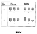
- Catalyst D contained the noble metal inhomogeneously distributed over the cross-section of the honeycomb body, so that more noble metal was present at its edge (zone 1) than in the middle (zone 3). To achieve this, the precious metal impregnation was carried out in three steps.
- the honeycomb body was immersed in the aqueous solution of the noble metal salts without further measures.
- zone 3 was taped on both end faces of the honeycomb body, and before the third immersion step, both zone 2 and zone 3 were taped on both end faces of the honeycomb body.
- Catalyst D contained in zone 1, i.e. at the edge of the cross-section of the honeycomb body, 0.832 grams of precious metal per liter of catalyst volume, in zone 2 there were 0.620 grams and in zone 3, i. H. in the middle of the honeycomb body cross-section, 0.436 grams, each in the weight ratio Pt: Rh 5: 1.
- the catalysts A and D were reduced in the last step of the production over 8 hours at 550 ° C. in a hydrogen stream.
- Catalysts A and D of Example 1 were tested on an engine test bench, both fresh and after 20 hours of engine aging, the temperature of the exhaust gases reaching 1000 ° C. as the catalyst entered.
- the catalyst performance was checked using two tests.
- the space velocity in this test was 60,000 standard liters of exhaust gas per liter of catalyst volume per hour.
- the conversion of carbon monoxide, hydrocarbons and nitrogen oxides was determined as a function of the lambda value at 400 ° C exhaust gas temperature upstream of the catalyst and 60,000 standard liters of exhaust gas per liter of catalyst volume and hourly space velocity.
Landscapes
- Chemical & Material Sciences (AREA)
- Engineering & Computer Science (AREA)
- Chemical Kinetics & Catalysis (AREA)
- Materials Engineering (AREA)
- Organic Chemistry (AREA)
- Health & Medical Sciences (AREA)
- Combustion & Propulsion (AREA)
- Biomedical Technology (AREA)
- General Engineering & Computer Science (AREA)
- Mechanical Engineering (AREA)
- Toxicology (AREA)
- Environmental & Geological Engineering (AREA)
- Analytical Chemistry (AREA)
- General Chemical & Material Sciences (AREA)
- Oil, Petroleum & Natural Gas (AREA)
- Catalysts (AREA)
- Exhaust Gas Treatment By Means Of Catalyst (AREA)
- Exhaust Gas After Treatment (AREA)
Description
- Die Erfindung bezieht sich auf einen Monolith- bzw. wabenförmigen Katalysator, insbesondere zur Reinigung der Abgase von Brennkraftmaschinen, aus einem mit parallelen Strömungskanälen durchzogenen inerten keramischen oder metallischen Träger, einer darauf angeordneten Schicht aus katalyseförderndem Metalloxid und einer von dem Metalloxid getragenen katalytisch aktiven Komponente. Der Katalysator weist verbessertes Anspringverhalten auf.
- Eine wichtige Eigenschaft von Katalysatoren des Monolith- oder Wabentyps ist die Geschwindigkeit, mit der der Katalysator bei Beaufschlagung mit einem heißen, zu behandelnden Gas die Betriebstemperatur erlangt. Die Anwendung solcher Katalysatoren als Chemiekatalysatoren oder Abgasreinigungskatalysatoren. z. B. für industrielle Abgase oder Motorabgase läßt sich wesentlich durch die Verbesserung dieser Eigenschaft vereinfachen.
- Dies wurde bislang durch eine mehr oder weniger kostspielige Erhöhung der Menge an katalytisch aktivem Material oder durch Wärmedämmungsmaßnahmen an der Katalysastoreinheit zu erreichen versucht.
- Die Erfindung eröffnet einen neuen Weg zur Lösung des Problems.
- Gegenstand der Erfindung ist ein Monolith- bzw. wabenförmiger Katalysator, insbesondere zur Reinigung der Abgase von Brennkraftmaschinen, aus einem mit parallelen Strömungskanälen durchzogenen inerten keramischen oder metallischen Träger, einer darauf angeordneten Schicht aus katalyseförderndem Metalloxid und einer von dem Metalloxid getragenen katalytisch aktiven Komponente, welcher dadurch gekennzeichnet ist, daß das katalysefördernde Metalloxid zwischen Mittelachse und Peripherie des Trägers im wesentlichen gleichverteilt ist und die Konzentration der katalytisch aktiven Komponente von der Mittelachse zur Peripherie des Trägers ansteigt.
- Durch erfindungsgemäße Konzentrationsverteilung der katalytisch aktiven Komponente wird eine ausgeglichenere Wärmeentwicklung beim Einsetzen und Ablaufen exothermer Reaktionen bewirkt, indem die Wirkung des naturgegebenen Geschwindigkeitsprofils bei Durchströmung von Monolithen oder Waben, ja sogar leeren Rohren durch Gase, welches um die Mittelachse stärker als an den Randzonen ausgeprägt ist, ausgeglichen wird.
- Der erfindungsgemäße Monolith- bzw. Wabenkatalysator kann z. B. in solchen Fällen eingesetzt werden, bei denen die zum Katalysator führenden Anströmwege gleichen Querschnitt wie der Monolith bzw. die Wabe aufweisen, also von Anfang an eine gleichmäßigere Gasbeaufschlagung der Anströmfläche vorliegt.
- Ferner wirkt die von der Mittelachse zur Peripherie ansteigende Edelmetall-Konzentration einer Minderung der Konversion in den außenliegenden Monolith- bzw. Wabenbezirken infolge Fahrtwindbedingter Abkühlung des Schadstoffkonverters, in dem sich der Monolith bzw. die Wabe befindet, entgegen.
- Das auf die Beladung mit katalytisch aktiver Komponente erfindungsgemäß anzuwendende Konzentrationsprofil, das stufenweise oder kontinuierlich ausgebildet werden soll, läßt sich z. B. stufenweise einstellen, indem eine Stirnfläche während der in mehreren Stufen erfolgenden Beladung durch eine das Zentrum oder den Randbereich abdeckende Maske, z. B. in Form einer Scheibe bzw. eines Ringes, von dem jeweiligen Auftrag freigehalten und die freibleibende Fläche entsprechend der gewünschten Konzentration ein- oder mehrmals mit der aufzutragenden Substanz beladen wird.
- Eine kontinuierliche Beladung der katalytisch aktiven Komponente kann durch eine nach Art eines Fotozentralverschlusses stufenlos öffnende oder schließende Lamellenanordnung erreicht werden, wobei diese entsprechend der für eine gewünschte örtliche Beladung erforderlichen Verweilzeit mit variierbarer Geschwindigkeit geöffnet oder geschlossen wird.
- Eine kontinuierliche Beladung mit der katalytisch aktiven Komponente kann aber auch erreicht werden, indem eine auf einer Spiralbahn um die Mittelachse des Monolithen bzw. der Wabe rotierende Beaufschlagungsdüse, die gleichzeitig mehrere Kanäle bestreichen kann, mit der eine gewünschte örtliche Beladung erforderlichen Bewegungsgeschwindigkeit betätigt wird.
- Die Zufuhrleitung bzw. die Zufuhrdüse kann auch als Drehschieber in Form einer über einer Stirnfläche des Monolithen bzw. der Wabe rotierenden Schlitzplatte mit kontinuierlich längenveränderbarem Schlitz ausgebildet sein.
- In Verbindung mit der Anwendung der genannten Masken kann auch über die Strömungsgeschwindigkeit einer Beladungsflüssigkeit die örtliche Konzentration der Beladung beeinflußt werden, wobei letztere im allgemeinen bei Erhöhung des Durchsatzes durch die Kanäle des Monolithen bzw. der Wabe ansteigt.
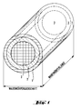
- Die Erfindung wird im folgenden anhand von Ausführungsbeispielen in Verbindung mit einer einfachen Versuchsanordnung und einer schematischen Zeichnung mit Figur 1 und Figur 2 näher erläutert.
- Es wurden zwei Auto-Abgas-Katalysatoren (bezeichnet als Katalysator A und D) mit einem Wabenkörper aus Cordierit mit 62 Zellen/cm² (400 Zellen/inch²), Durchmesser 118 mm (4.66 inch), Länge 152.4 mm (6 inch), Wandstärke 0.1524 mm (6 mil), hergestellt.
- Die Herstellung der Katalysatoren erfolgte in folgenden Schritten:
Der erste Schritt, die Herstellung einer katalyseförderndes mit Promotoren dotiertes Metalloxid enthaltenden Beschichtungssuspension, war identisch für beide Katalysatoren und umfaßte die Dispergierung von hochreinem Gamma-Aluminiumoxidpulver mit einer spezifischen Oberfläche von 180 m²/g in Wasser. Zu dieser Aluminiumoxiddispersion wurden nacheinander unter kräftigem Rühren Cercarbonat und Zirkoncarbonat zugegeben, so daß für 100 Gewichtsteile Al₂O₃, 60 Gewichtsteile CeO₂ und 3 Gewichtsteile ZrO₂ vorlagen. - Der zweite Schritt, die Belegung des Wabenkörpers mit der bereiteten Dispersion, erfolgte bei Katalysator A, dem Vergleichskatalysator, durch langsames Eintauchen des Wabenkörpers in die Dispersion, langsames Herausziehen, Freiblasen der Wabenkörper-Kanäle mittels Luft und anschließendes 10minütiges Trockenblasen des so belegten Wabenkörpers mit Luft bei einer Temperatur von 120° C.
- Dieser Vorgang wurde 3 x wiederholt. Anschließend wurde der mit der dotierten Al₂O₃-Schicht belegte trockene Wabenkörper während 2 Stunden bei 600° C mit Luft durchströmt, um das Cer- und Zirkoncarbonat in die entsprechenden Oxide umzusetzen. Der so belegte Wabenkörper enthielt 120 Gramm Beschichtung pro Liter Wabenkörper-Volumen.
- Beim erfindungsgemäßen Katalysator D wurde die Oxidbeschichtung wie bei Katalysator A aufgebracht.
- Der dritte Schritt, gerichtet auf die Herstellung eines Autoabgaskatalysators, betraf die Aufbringung des Edelmetalls.
- Für die Katalysatoren A und D wurde hierzu eine wäßrige Lösung von H₂PtCl₆ und RhCl₃ verwendet. Die gesamte Menge Edelmetall auf dem Katalysator entspricht 0.714 Gramm pro Liter Katalysatorvolumen im Gewichtsmengenverhältnis verhältnis Pt : Rh = 5 : 1.
- Für Katalysator A, den Vergleichskatalysator, erfolgte die Edelmetallaufbringung durch einmaliges Eintauchen des mit der Oxidbeschichtung belegten Wabenkörpers in wäßrige Edelmetall-Lösung, anschließendes 4stündiges Trocknen an Luft bei 250° C und 2stündiges Kalzinieren bei 600° C in Luft. Katalysator A enthielt die Edelmetalle sowohl über dem Wabenkörperquerschnitt als auch über die Wabenkörperlänge homogen verteilt.
- Katalysator D enthielt das Edelmetall über dem Wabenkörperquerschnitt inhomogen verteilt, so daß an dessen Rand (Zone 1) mehr Edelmetall vorlag als in dessen Mitte (Zone 3). Um dies zu erreichen, wurde die Edelmetallimprägnierung in drei Schritten durchgeführt.
- Im ersten Tauchschritt wurde der Wabenkörper ohne weitere Maßnahmen in die wäßrige Lösung der Edelmetallsalze getaucht. Vor dem zweiten Schritt wurde Zone 3 auf beiden Stirnflächen des Wabenkörpers abgeklebt, und vor dem dritten Tauchschritt wurden sowohl Zone 2 als auch Zone 3 auf beiden Stirnflächen des Wabenkörpers abgeklebt.
- Nach diesen drei Tauchschritten erfolgte eine 4stündige Trocknung an Luft bei 250° C und anschließend eine 2stündige Kalzinierung in Luft bei 600° C.
- Katalysator D enthielt in Zone 1, d.h. am Rand des Wabenkörperquerschnitts, 0.832 Gramm Edelmetall pro Liter Katalysatorvolumen, in Zone 2 waren 0.620 Gramm vorhanden und in Zone 3, d. h. in der Mitte des Wabenkörperquerschnitts, 0.436 Gramm, jeweils im Gewichtsverhältnis Pt : Rh = 5 : 1.
- Die Katalysatoren A und D wurden im letzten Schritt der Herstellung während 8 Stunden bei 550° C im Wasserstoffstrom reduziert.
- Die Verteilung von Washcoat- und Edelmetallmenge über dem Wabenkörperquerschnitt ist in Abbildung 2 für die Katalysatoren A und D dargestellt (R = Abstand zwischen Mittelachse und Peripherie (Pfeilspitze), 1, 2 und 3 bedeuten die Zonen).
- Die Katalysatoren A und D von Beispiel 1 wurden an einem Motorprüfstand, sowohl frisch als auch nach einer 20stündigen Motoralterung, geprüft, wobei die Temperatur der Abgase bei der Alterung am Eintritt des Katalysators 1000° C erreichte.
- Für die Überprüfung der Katalysatorleistung und für die Motoralterung wurde ein 1.8 l-Ottomotor verwendet. Alle Tests wurden mit bleifreiem Superbenzin gefahren.
- Die Überprüfung der Katalysatorleistung erfolgte anhand von zwei Tests.
- Im ersten Test wurde das Anspringverhalten des Katalysators überprüft, d. h. es wurde die Temperatur bestimmt, bei der 50 % der Kohlenwasserstoffe, des Kohlenmonoxids und der Stickoxide umgewandelt werden. Dies erfolgte bei Lambda = 1.02 für Kohlenmonoxid und Kohlenwasserstoffe und bei Lambda = 0.9840 für die Stickoxide. Die Raumgeschwindigkeit bei diesem Test betrug 60.000 Normliter Abgas pro Liter Katalysatorvolumen und Stunde.
- Im zweiten Test wurde die Konvertierung von Kohlenmonoxid, Kohlenwasserstoffen und Stickoxiden in Abhängigkeit vom Lambda-Wert bei 400° C Abgastemperatur vor Katalysator und 60.000 Normliter Abgas pro Liter Katalysatorvolumen und Stunde Raumgeschwindigkeit bestimmt.
- Das Anspringverhalten der frischen Katalysatoren A und D ist in Tabelle 1 dargestellt.
- Aus den Ergebnissen folgt, daß die Anspringtemperatur für Kohlenmonoxid- und Kohlenwasserstoffkonversion durch die erfindungsgemäße Verteilung des Edelmetalls über dem Wabenkörperquerschnitt um 6 bzw. 7° C gesenkt werden kann.
- Das Anspringverhalten der motorgealterten Katalysatoren A und D ist in Tabelle 2 dargestellt.
- Aus diesen Ergebnissen ist noch deutlicher zu sehen, daß durch eine gezielte Positionierung der Edelmetalle über den Querschnitt der Wabenkörper die Anspringtemperatur für Kohlenmonoxid und Kohlenwasserstoffe um 10 bzw. 9° C und für die Stickoxide um 41° C gesenkt werden kann.


Claims (1)
- Monolith- bzw. wabenförmiger Katalysator, insbesondere zur Reinigung der Abgase von Brennkraftmaschinen, aus einem mit parallelen Strömungskanälen durchzogenen inerten keramischen oder metallischen Träger, einer darauf angeordneten Schicht aus katalyseförderndem Metalloxid und einer von dem Metalloxid getragenen katalytisch aktiven Komponente,
dadurch gekennzeichnet,
daß das katalysefördernde Metalloxid zwischen Mittelachse und Peripherie des Trägers im wesentlichen gleichverteilt ist, jedoch die Konzentration der katalytisch aktiven Komponente von der Mittelachse zur Peripherie des Trägers ansteigt.
Applications Claiming Priority (2)
| Application Number | Priority Date | Filing Date | Title |
|---|---|---|---|
| DE3912915 | 1989-04-20 | ||
| DE3912915A DE3912915C1 (de) | 1989-04-20 | 1989-04-20 |
Related Parent Applications (2)
| Application Number | Title | Priority Date | Filing Date |
|---|---|---|---|
| EP90107181.1 Division | 1990-04-14 | ||
| EP90107181A Division EP0399203B1 (de) | 1989-04-20 | 1990-04-14 | Monolith-bzw. wabenförmiger Katalysator |
Publications (2)
| Publication Number | Publication Date |
|---|---|
| EP0459534A1 EP0459534A1 (de) | 1991-12-04 |
| EP0459534B1 true EP0459534B1 (de) | 1992-12-09 |
Family
ID=6379016
Family Applications (2)
| Application Number | Title | Priority Date | Filing Date |
|---|---|---|---|
| EP90107181A Expired - Lifetime EP0399203B1 (de) | 1989-04-20 | 1990-04-14 | Monolith-bzw. wabenförmiger Katalysator |
| EP91113441A Expired - Lifetime EP0459534B1 (de) | 1989-04-20 | 1990-04-14 | Monolith- bzw. wabenförmiger Katalysator |
Family Applications Before (1)
| Application Number | Title | Priority Date | Filing Date |
|---|---|---|---|
| EP90107181A Expired - Lifetime EP0399203B1 (de) | 1989-04-20 | 1990-04-14 | Monolith-bzw. wabenförmiger Katalysator |
Country Status (10)
| Country | Link |
|---|---|
| US (1) | US5043311A (de) |
| EP (2) | EP0399203B1 (de) |
| JP (1) | JP2962768B2 (de) |
| KR (1) | KR910018081A (de) |
| BR (1) | BR9001710A (de) |
| DD (1) | DD293741A5 (de) |
| DE (3) | DE3912915C1 (de) |
| ES (2) | ES2020157T3 (de) |
| MX (1) | MX173865B (de) |
| ZA (1) | ZA902062B (de) |
Families Citing this family (39)
| Publication number | Priority date | Publication date | Assignee | Title |
|---|---|---|---|---|
| FI94455C (fi) * | 1992-08-28 | 1995-09-11 | Kemira Oy | Katalysaattori ja sen valmistusmenetelmä |
| GB2275624A (en) * | 1993-03-05 | 1994-09-07 | Jaguar Cars | Exhaust converter structure |
| JP3498357B2 (ja) * | 1993-05-28 | 2004-02-16 | マツダ株式会社 | 排気ガス浄化用触媒の製造方法 |
| FR2720296B1 (fr) * | 1994-05-27 | 1996-07-12 | Rhone Poulenc Chimie | Composés à base d'alumine, d'oxyde de cérium et d'oxyde de zirconium à réductibilité élevée, leur procédé de préparation et leur utilisation dans la préparation de catalyseurs. |
| JP4201356B2 (ja) * | 1996-06-20 | 2008-12-24 | 本田技研工業株式会社 | 内燃機関用排ガス浄化装置 |
| US6596243B1 (en) | 1996-06-20 | 2003-07-22 | Honda Giken Kogyo Kabushiki Kaisha | Catalyst element for purifying exhaust gases from internal combustion engine |
| DE19709102A1 (de) * | 1997-03-06 | 1998-10-08 | Degussa | Katalysatorsystem zur Abgasreinigung von Dieselmotoren |
| DE19714732A1 (de) * | 1997-04-09 | 1998-10-15 | Degussa | Verfahren zum Abscheiden von katalytisch aktiven Komponenten auf hochoberflächigen Trägermaterialien |
| DE19819372C2 (de) * | 1998-04-30 | 2000-03-02 | Degussa | Verfahren zur Verminderung des Stickoxidgehaltes der Abgase eines Verbrennungsmotors |
| DE19962544A1 (de) | 1999-12-23 | 2001-07-19 | Degussa | Verfahren zum Beschichten eines keramischen Wabenkörpers |
| RU2177363C2 (ru) * | 2000-03-17 | 2001-12-27 | Рахманов Геннадий Жанович | Каталитический нейтрализатор |
| JP2002177794A (ja) * | 2000-09-29 | 2002-06-25 | Denso Corp | セラミック触媒体およびセラミック担体 |
| US20030103875A1 (en) * | 2001-09-26 | 2003-06-05 | Siemens Westinghouse Power Corporation | Catalyst element having a thermal barrier coating as the catalyst substrate |
| US7541005B2 (en) * | 2001-09-26 | 2009-06-02 | Siemens Energy Inc. | Catalytic thermal barrier coatings |
| US7371352B2 (en) * | 2001-09-26 | 2008-05-13 | Siemens Power Generation, Inc. | Catalyst element having a thermal barrier coating as the catalyst substrate |
| DE10201042A1 (de) * | 2002-01-14 | 2003-08-07 | Eberspaecher J Gmbh & Co | Abgasanlage für Verbrennungsmotoren, mit einem katalytischen Abgaskonverter |
| JP4409959B2 (ja) * | 2002-03-29 | 2010-02-03 | イビデン株式会社 | セラミックフィルタおよび排ガス浄化装置 |
| DE10230330A1 (de) * | 2002-07-05 | 2004-01-22 | Audi Ag | Verfahren und Vorrichtung zum räumlich inhomogenen Beschichten eines Wabenkörpers und inhomogen beschichteter Wabenkörper |
| US7651753B2 (en) | 2002-07-05 | 2010-01-26 | Emitec Gesellschaft Fuer Emissionstechnologie Mbh | Process and apparatus for spatially inhomogeneously coating a honeycomb body and inhomogeneously coated honeycomb body |
| EP1598111A1 (de) * | 2004-05-15 | 2005-11-23 | Delphi Technologies, Inc. | Katalysator mit Konzentrationsgradienten zur Verwendung in einem katalytischen Filter |
| DE102005020963B4 (de) * | 2005-05-06 | 2007-05-24 | Audi Ag | Abgaskatalysator für eine Brennkraftmaschine |
| GB0603942D0 (en) | 2006-02-28 | 2006-04-05 | Johnson Matthey Plc | Exhaust system for a spark-ignited internal combustion engine |
| US7947102B2 (en) * | 2006-12-21 | 2011-05-24 | Dow Global Technologies Llc | Soot filter |
| DE102006061685A1 (de) * | 2006-12-28 | 2008-07-03 | Robert Bosch Gmbh | Filterelement und Filter zur Abgasnachbehandlung einer Brennkraftmaschine |
| FR2912666B1 (fr) * | 2007-02-20 | 2009-05-08 | Peugeot Citroen Automobiles Sa | Convertisseur catalytique pour le traitement des gaz d'echappement des moteurs a combustion interne, ligne d'echappement comportant un tel convertisseur et procede de fabrication de ce convertisseur |
| DE102007029418A1 (de) * | 2007-06-26 | 2009-01-08 | Robert Bosch Gmbh | Katalysatorelement, Katalysator zur Abgasnachbehandlung einer Brennkraftmaschine und Verfahren zur Herstellung eines erfindungsgemäßen Katalysatorelements |
| GB0716833D0 (en) | 2007-08-31 | 2007-10-10 | Nunn Andrew D | On board diagnostic system |
| DE102007056213A1 (de) * | 2007-11-22 | 2009-05-28 | Robert Bosch Gmbh | Verfahren zur Herstellung eines von Abgas durchströmbaren Formkörpers sowie Abgasanlage einer Brennkraftmaschine |
| JP2009136833A (ja) * | 2007-12-10 | 2009-06-25 | Toyota Motor Corp | 排気ガス浄化用モノリス触媒の製造方法とモノリス触媒 |
| JP5639343B2 (ja) * | 2009-03-31 | 2014-12-10 | 日本碍子株式会社 | ハニカム触媒体 |
| DE102010053603A1 (de) | 2010-11-12 | 2012-05-16 | Bayerische Motoren Werke Aktiengesellschaft | Katalysator |
| JP5757297B2 (ja) * | 2013-01-23 | 2015-07-29 | トヨタ自動車株式会社 | 触媒コンバーター |
| GB201303396D0 (en) * | 2013-02-26 | 2013-04-10 | Johnson Matthey Plc | Oxidation catalyst for a combustion engine |
| DE102013204401B4 (de) * | 2013-03-13 | 2016-06-30 | Mtu Friedrichshafen Gmbh | System zur Abgasnachbehandlung, Verfahren und Brennkraftmaschine |
| DE102013204405A1 (de) * | 2013-03-13 | 2014-09-18 | Mtu Friedrichshafen Gmbh | System zur Abgasnachbehandlung für eine Brennkraftmaschine, Verfahren zur Beeinflussung einer Abgas-Zusammensetzung und Brennkraftmaschine |
| US10688476B2 (en) * | 2014-09-10 | 2020-06-23 | Cataler Corporation | Exhaust gas purification catalyst |
| US9482131B2 (en) | 2015-01-08 | 2016-11-01 | Tenneco Automotive Operating Company Inc. | Exhaust system with zone coated catalyst |
| US10099212B2 (en) * | 2016-03-15 | 2018-10-16 | Cummins Emission Solutions Inc. | Hydrocarbon storage optimization and coking prevention on an oxidation catalyst |
| GB2557644A (en) * | 2016-12-14 | 2018-06-27 | Ford Global Tech Llc | Improvements in or relating to flow optimised washcoating |
Family Cites Families (12)
| Publication number | Priority date | Publication date | Assignee | Title |
|---|---|---|---|---|
| JPS5130555B2 (de) * | 1971-09-03 | 1976-09-01 | ||
| US3791143A (en) * | 1971-11-10 | 1974-02-12 | Engelhard Min & Chem | Process and apparatus |
| US3908047A (en) * | 1973-12-05 | 1975-09-23 | Gulf Research Development Co | Process for coating an alumina base |
| US3904551A (en) * | 1973-12-19 | 1975-09-09 | Grace W R & Co | Process for preparing an auto exhaust catalytic converter |
| US3901821A (en) * | 1974-03-18 | 1975-08-26 | Air Prod & Chem | Multi-component catalyst |
| US4128506A (en) * | 1978-01-23 | 1978-12-05 | General Motors Corporation | Platinum-rhodium catalyst for automotive emission control |
| JPS56129043A (en) * | 1980-03-14 | 1981-10-08 | Ngk Insulators Ltd | Honeycomb structure of ceramic |
| US4318888A (en) * | 1980-07-10 | 1982-03-09 | General Motors Corporation | Wound foil structure comprising distinct catalysts |
| US4340505A (en) * | 1981-04-28 | 1982-07-20 | Johnson Matthey, Inc. | Reducing precious metal use in catalyst substrates |
| JPH084749B2 (ja) * | 1985-01-21 | 1996-01-24 | 日本碍子株式会社 | セラミツクハニカム構造体 |
| FR2622126B1 (fr) * | 1987-10-21 | 1991-06-14 | Procatalyse Ste Fse Produits C | Catalyseur pour le traitement des gaz d'echappement des moteurs a combustion interne et procede de fabrication de ce catalyseur |
| JPH0441937Y2 (de) * | 1987-12-28 | 1992-10-02 |
-
1989
- 1989-04-20 DE DE3912915A patent/DE3912915C1/de not_active Expired - Lifetime
-
1990
- 1990-03-16 ZA ZA902062A patent/ZA902062B/xx unknown
- 1990-04-10 BR BR909001710A patent/BR9001710A/pt not_active IP Right Cessation
- 1990-04-14 ES ES199090107181T patent/ES2020157T3/es not_active Expired - Lifetime
- 1990-04-14 DE DE9191113441T patent/DE59000579D1/de not_active Expired - Fee Related
- 1990-04-14 EP EP90107181A patent/EP0399203B1/de not_active Expired - Lifetime
- 1990-04-14 ES ES199091113441T patent/ES2036420T3/es not_active Expired - Lifetime
- 1990-04-14 DE DE9090107181T patent/DE59000196D1/de not_active Expired - Lifetime
- 1990-04-14 EP EP91113441A patent/EP0459534B1/de not_active Expired - Lifetime
- 1990-04-18 DD DD90339853A patent/DD293741A5/de not_active IP Right Cessation
- 1990-04-18 KR KR1019900005405A patent/KR910018081A/ko not_active Withdrawn
- 1990-04-19 MX MX020381A patent/MX173865B/es unknown
- 1990-04-19 US US07/510,266 patent/US5043311A/en not_active Expired - Lifetime
- 1990-04-20 JP JP2103228A patent/JP2962768B2/ja not_active Expired - Lifetime
Also Published As
| Publication number | Publication date |
|---|---|
| US5043311A (en) | 1991-08-27 |
| ZA902062B (en) | 1990-12-28 |
| BR9001710A (pt) | 1991-05-21 |
| DE59000196D1 (de) | 1992-08-13 |
| ES2036420T3 (es) | 1993-05-16 |
| JPH03143548A (ja) | 1991-06-19 |
| KR910018081A (ko) | 1991-11-30 |
| ES2020157A4 (es) | 1991-08-01 |
| DE59000579D1 (de) | 1993-01-21 |
| DD293741A5 (de) | 1991-09-12 |
| EP0399203B1 (de) | 1992-07-08 |
| DE3912915C1 (de) | 1990-12-13 |
| ES2020157T3 (es) | 1993-03-16 |
| MX173865B (es) | 1994-04-07 |
| EP0399203A3 (de) | 1991-04-10 |
| JP2962768B2 (ja) | 1999-10-12 |
| EP0459534A1 (de) | 1991-12-04 |
| EP0399203A2 (de) | 1990-11-28 |
Similar Documents
| Publication | Publication Date | Title |
|---|---|---|
| EP0459534B1 (de) | Monolith- bzw. wabenförmiger Katalysator | |
| EP1974809B1 (de) | Doppelschichtiger Dreiweg-Katalysator | |
| EP2038046B1 (de) | Doppelschichtiger dreiweg-katalysator und dessen verwendung | |
| DE4021570C2 (de) | ||
| EP0432534B1 (de) | Katalysator zur Reinigung der Abgase von Dieselmotoren | |
| EP0314058B1 (de) | Platin-freier Dreiweg-Katalysator. | |
| DE69529347T2 (de) | Anliegender Katalysator und Verfahren zu seinem Betrieb | |
| DE4213018C1 (de) | Katalysator zur oxidativen Reinigung der Abgase von Dieselmotoren | |
| EP0314057B1 (de) | Rhodium-freier Dreiwegkatalysator | |
| DE69111796T2 (de) | Mehrstufiges Dreiwegkatalysatorsystem. | |
| DE4004572C2 (de) | Trägerkatalysator zur Reinigung von Abgasen | |
| DE19742705A1 (de) | Abgasreinigungskatalysator | |
| DE102018106415A1 (de) | Katalytisches wandstromfilter mit einem ammoniak-slip-katalysator | |
| DE102016111148A1 (de) | Ammoniak-Sperrkatalysator, ausgestaltet um der Erste in einem SCR-System zu sein | |
| DE3735151A1 (de) | Verfahren zum reinigen von abgasen | |
| DE2907106A1 (de) | Katalysator zur reinigung der abgase von verbrennungskraftmaschinen | |
| DE19606822A1 (de) | Katalysator zur Abgasreinigung | |
| DE69422938T2 (de) | Katalysator zur Reinigung von Abgasen aus Dieselmotoren | |
| DE102017125040A1 (de) | Kohlenwasserstoffinjektion durch kleinporigen cu-zeolith-katalysator | |
| DE69008679T2 (de) | Dreiwegkatalysator zur Kraftwagenemissionskontrolle. | |
| DE102021100520A1 (de) | Abgasreinigungsvorrichtung | |
| DE3826155C2 (de) | ||
| DE19713103A1 (de) | Abgasreinigungskatalysator und dessen Herstellungsverfahren | |
| DE102018106329A1 (de) | SCRF mit rückwärtigem Auf-Wand-Design | |
| DE69309049T2 (de) | Vorrichtung zur reinigung von abgasen |
Legal Events
| Date | Code | Title | Description |
|---|---|---|---|
| PUAI | Public reference made under article 153(3) epc to a published international application that has entered the european phase |
Free format text: ORIGINAL CODE: 0009012 |
|
| 17P | Request for examination filed |
Effective date: 19910810 |
|
| AC | Divisional application: reference to earlier application |
Ref document number: 399203 Country of ref document: EP |
|
| AK | Designated contracting states |
Kind code of ref document: A1 Designated state(s): DE ES FR GB IT SE |
|
| 17Q | First examination report despatched |
Effective date: 19920519 |
|
| GRAA | (expected) grant |
Free format text: ORIGINAL CODE: 0009210 |
|
| AC | Divisional application: reference to earlier application |
Ref document number: 399203 Country of ref document: EP |
|
| AK | Designated contracting states |
Kind code of ref document: B1 Designated state(s): DE ES FR GB IT SE |
|
| ITF | It: translation for a ep patent filed | ||
| ET | Fr: translation filed | ||
| GBT | Gb: translation of ep patent filed (gb section 77(6)(a)/1977) |
Effective date: 19921209 |
|
| REF | Corresponds to: |
Ref document number: 59000579 Country of ref document: DE Date of ref document: 19930121 |
|
| REG | Reference to a national code |
Ref country code: ES Ref legal event code: FG2A Ref document number: 2036420 Country of ref document: ES Kind code of ref document: T3 |
|
| PLBE | No opposition filed within time limit |
Free format text: ORIGINAL CODE: 0009261 |
|
| STAA | Information on the status of an ep patent application or granted ep patent |
Free format text: STATUS: NO OPPOSITION FILED WITHIN TIME LIMIT |
|
| 26N | No opposition filed | ||
| EAL | Se: european patent in force in sweden |
Ref document number: 91113441.9 |
|
| REG | Reference to a national code |
Ref country code: GB Ref legal event code: IF02 |
|
| PGFP | Annual fee paid to national office [announced via postgrant information from national office to epo] |
Ref country code: SE Payment date: 20020327 Year of fee payment: 13 |
|
| PGFP | Annual fee paid to national office [announced via postgrant information from national office to epo] |
Ref country code: ES Payment date: 20020418 Year of fee payment: 13 |
|
| PG25 | Lapsed in a contracting state [announced via postgrant information from national office to epo] |
Ref country code: SE Free format text: LAPSE BECAUSE OF NON-PAYMENT OF DUE FEES Effective date: 20030415 Ref country code: ES Free format text: LAPSE BECAUSE OF NON-PAYMENT OF DUE FEES Effective date: 20030415 |
|
| REG | Reference to a national code |
Ref country code: GB Ref legal event code: 732E |
|
| REG | Reference to a national code |
Ref country code: GB Ref legal event code: 732E |
|
| EUG | Se: european patent has lapsed | ||
| REG | Reference to a national code |
Ref country code: ES Ref legal event code: FD2A Effective date: 20030415 |
|
| PGFP | Annual fee paid to national office [announced via postgrant information from national office to epo] |
Ref country code: DE Payment date: 20070423 Year of fee payment: 18 |
|
| PGFP | Annual fee paid to national office [announced via postgrant information from national office to epo] |
Ref country code: GB Payment date: 20070426 Year of fee payment: 18 |
|
| PGFP | Annual fee paid to national office [announced via postgrant information from national office to epo] |
Ref country code: IT Payment date: 20070626 Year of fee payment: 18 |
|
| PGFP | Annual fee paid to national office [announced via postgrant information from national office to epo] |
Ref country code: FR Payment date: 20070416 Year of fee payment: 18 |
|
| GBPC | Gb: european patent ceased through non-payment of renewal fee |
Effective date: 20080414 |
|
| PG25 | Lapsed in a contracting state [announced via postgrant information from national office to epo] |
Ref country code: DE Free format text: LAPSE BECAUSE OF NON-PAYMENT OF DUE FEES Effective date: 20081101 |
|
| REG | Reference to a national code |
Ref country code: FR Ref legal event code: ST Effective date: 20081231 |
|
| PG25 | Lapsed in a contracting state [announced via postgrant information from national office to epo] |
Ref country code: FR Free format text: LAPSE BECAUSE OF NON-PAYMENT OF DUE FEES Effective date: 20080430 |
|
| PG25 | Lapsed in a contracting state [announced via postgrant information from national office to epo] |
Ref country code: GB Free format text: LAPSE BECAUSE OF NON-PAYMENT OF DUE FEES Effective date: 20080414 |
|
| PG25 | Lapsed in a contracting state [announced via postgrant information from national office to epo] |
Ref country code: IT Free format text: LAPSE BECAUSE OF NON-PAYMENT OF DUE FEES Effective date: 20080414 |