EP0459305A2 - Appareil de chauffage à haute-fréquence - Google Patents
Appareil de chauffage à haute-fréquence Download PDFInfo
- Publication number
- EP0459305A2 EP0459305A2 EP91108386A EP91108386A EP0459305A2 EP 0459305 A2 EP0459305 A2 EP 0459305A2 EP 91108386 A EP91108386 A EP 91108386A EP 91108386 A EP91108386 A EP 91108386A EP 0459305 A2 EP0459305 A2 EP 0459305A2
- Authority
- EP
- European Patent Office
- Prior art keywords
- opening
- antenna
- heating chamber
- frequency
- detector
- Prior art date
- Legal status (The legal status is an assumption and is not a legal conclusion. Google has not performed a legal analysis and makes no representation as to the accuracy of the status listed.)
- Granted
Links
- 238000010438 heat treatment Methods 0.000 title claims abstract description 58
- 239000004020 conductor Substances 0.000 claims description 9
- 235000013305 food Nutrition 0.000 description 14
- 238000001514 detection method Methods 0.000 description 7
- XLYOFNOQVPJJNP-UHFFFAOYSA-N water Substances O XLYOFNOQVPJJNP-UHFFFAOYSA-N 0.000 description 5
- 230000004048 modification Effects 0.000 description 3
- 238000012986 modification Methods 0.000 description 3
- 235000015278 beef Nutrition 0.000 description 2
- 239000003990 capacitor Substances 0.000 description 2
- 241000251468 Actinopterygii Species 0.000 description 1
- 230000005540 biological transmission Effects 0.000 description 1
- 239000007767 bonding agent Substances 0.000 description 1
- 230000001419 dependent effect Effects 0.000 description 1
- 230000007774 longterm Effects 0.000 description 1
- 238000004519 manufacturing process Methods 0.000 description 1
- 229910000679 solder Inorganic materials 0.000 description 1
Images

Classifications
-
- H—ELECTRICITY
- H05—ELECTRIC TECHNIQUES NOT OTHERWISE PROVIDED FOR
- H05B—ELECTRIC HEATING; ELECTRIC LIGHT SOURCES NOT OTHERWISE PROVIDED FOR; CIRCUIT ARRANGEMENTS FOR ELECTRIC LIGHT SOURCES, IN GENERAL
- H05B6/00—Heating by electric, magnetic or electromagnetic fields
- H05B6/64—Heating using microwaves
- H05B6/6447—Method of operation or details of the microwave heating apparatus related to the use of detectors or sensors
-
- H—ELECTRICITY
- H05—ELECTRIC TECHNIQUES NOT OTHERWISE PROVIDED FOR
- H05B—ELECTRIC HEATING; ELECTRIC LIGHT SOURCES NOT OTHERWISE PROVIDED FOR; CIRCUIT ARRANGEMENTS FOR ELECTRIC LIGHT SOURCES, IN GENERAL
- H05B6/00—Heating by electric, magnetic or electromagnetic fields
- H05B6/64—Heating using microwaves
- H05B6/66—Circuits
- H05B6/68—Circuits for monitoring or control
Definitions
- the present invention relates to a high-frequency heating apparatus such as an electronic range, in which a high-frequency heat source, e.g. a magnetron is controlled by detecting field intensity in a cabinet.
- a high-frequency heat source e.g. a magnetron
- a high-frequency heating apparatus is known from, for example, Japanese Patent Laid-Open Publication No. 59-207595 in which by using transmitting and receiving antennas confronting a heating chamber, changes of dielectric constant of an article to be heated (hereinbelow, referred to as a "food") dependent upon temperature of the food are detected so as to control a high-frequency heat source.
- the known high-frequency heating apparatus in which the antennas confront the heating chamber has such a drawback that especially at the time of heating of the food, a large amount of water or oil from the food scatters in the cabinet and penetrate into a contact point between the receiving antenna and a detector, thereby resulting in great change in detection characteristics.
- an essential object of the present invention is to provide a high-frequency heating apparatus in which an antenna is provided outside a heating chamber so as not to be contaminated by water or oil scattered from a food in the heating chamber.
- a high-frequency heating apparatus comprises: a high-frequency oscillator for oscillating high-frequency electromagnetic wave by electric power supplied from a power source circuit; a heating chamber into which the high-frequency electromagnetic wave is supplied by said high-frequency oscillator; an antenna which is provided outside said heating chamber and adjacent to an opening of said heating chamber; a dielectric plate for covering the opening, which is provided in said heating chamber so as to confront said antenna through the opening; a detector which receives an output from said antenna and has a grounded portion such that said grounded portion is connected to said heating chamber; and a control circuit which receives an output from said detector so as to output a control signal to said power source circuit.
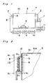
- a high-frequency heating apparatus K In the heating apparatus K, electromagnetic wave emitted from a high-frequency oscillator 1 is supplied, through a waveguide 2, into a high-frequency heating chamber 3 so as to heat a food 4 in a cabinet 30 having a shape of rectangular parallelepiped. Electromagnetic wave in the cabinet 30 is detected, via a dielectric plate 5 and an opening 6 of the cabinet 30, in direct current by a detector 8 provided with an antenna 7. The detector 8 has a grounded conductor whose one portion is connected to a wall of the cabinet 30. A current signal detected by the detector 8 is fed, through an amplifier 9, to a control circuit 10 leading to a power source circuit 11. Since the amplifier 9 is provided between the detector 8 and the control circuit 10, the power source circuit 11 can be controlled stably at a high signal level against noises.
- Fig. 2 and Figs. 3a to 3c show the opening 6 and the detector 8.
- the detector 8 is secured to a bracket 12 attached to an outer surface of the wall of the cabinet 30.
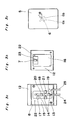
- the detector 8 is formed by a microstrip line including an active conductor 14 and grounded faces 15 and 16.
- the detector 8 further includes resistors 17, 18 and 19, a diode 20 and a capacitor 21.
- the grounded faces 15 and 16 are connected to each other by forming a through-hole or by a connecting conductor 22. Since the grounded face 16 is held in contact with the bracket 12, the grounded faces 15 and 16 of the microstrip line have a potential identical with that of the heating chamber 3, so that a microwave transmission circuit functioning stably is obtained.
- a conductor piece at the side of the grounded face 16 is connected to the active conductor 14 at the side of the grounded face 15 so as to act as the antenna 7.
- the dielectric plate 5 is fixed to an inner surface of the wall of the cabinet 30 by bonding agent, etc. so as to cover the opening 6. Therefore, the dielectric plate 5 confronts the antenna 7 through the opening 6 and prevents water and oil in the cabinet 30 from reaching the antenna 7 directly.
- Lead wires 24 and 25 are, respectively, attached to the active conductor 14 and the grounded face 15 by solder, etc. and are led to the amplifier 9.
- the opening 6 is of a crossed shape having crossing portions 6a and 6b and the crossing portions 6a and 6b are inclined at an angle ⁇ relative to a horizontal direction of the cabinet 30 as shown in Fig. 3c.
- the heating chamber 3 defines a rectangular contour having a straight portion 30A, etc. in a plane at which the opening 6 confronts the dielectric plate 5. Therefore, the crossing portions 6a and 6b extend obliquely relative to the straight portion 30A of the contour and thus, the antenna 7 is least likely to be affected by mode change of standing wave in the heating chamber 3.
- the crossing portions 6a and 6b deviate from a longitudinal direction of the antenna 7 as shown in Figs. 3b and 3c, average whole change of dielectric loss in the heating chamber 3 can be received by the antenna 7.
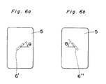
- the opening 6 has a crossed shape.
- the opening 6 is not restricted to the crossed shape but may have any elongated shape such as an opening 6' in Fig. 6a or an opening 6'' shown in Fig. 6b such that a longitudinal direction of the opening 6' or 6'' extends obliquely relative to the straight portion 30A of the contour.
- the longitudinal direction of the opening 6' or 6'' deviates from the longitudinal direction of the antenna 7.
- the opening 6 is formed in the side wall of the cabinet 30.
- the present invention can also be applied to an arrangement in which the opening 6 is formed in the top plate of the cabinet 30.
- Fig. 4 shows temperature characteristics of dielectric loss ( ⁇ r x tan ⁇ ) of beef or fish measured at a frequency of 2,400 MHz in the heating apparatus K. It is apparent from Fig. 4 that dielectric loss changes greatly among a frozen state, a defrozen state, a room temperature state and a heated state of the food. This phenomenon in which dielectric loss is great indicates that electromagnetic wave is well absorbed by the food.
- Fig. 5 shows one example of detection output in the case of heating beef from a frozen state in the heating apparatus K. From Figs. 4 and 5, it will be seen that when dielectric loss of the food is small, detection output is large. On the other hand, when dielectric loss of the food is large, detection output becomes small. Therefore, by controlling the power source circuit 11 on the basis of magnitude of detection output or trend of change of detection output, it becomes possible to automatically detect defreesing or heating of the food.
- the antenna is provided outside the heating chamber and electromagnetic wave from the opening of the cabinet is received through the dielectric plate so as to be detected. Furthermore, the grounded faces of the detector are connected to the heating chamber. Therefore, in accordance with the present invention, even if water or oil scatters from the food, such an undesirable phenomenon does not take place that the antenna is short-circuited to the grounded faces by water or oil of the food, so that stable control performance of the heating apparatus can be secured for a long term. Moreover, even if mass production of the heating apparatus is performed, the detector can function stably.
- the conductor piece of the printed circuit board which constitutes the detector formed by the microstrip line acts as the antenna, dimensional accuracy of the antenna is more excellent than an arrangement in which an antenna is provided outwardly of the printed circuit board or an arrangement in which a metallic rod acting as an antenna is vertically erected on the printed circuit board. Therefore, in accordance with the present invention, the antenna has stable microwave characteristics.
- the antenna is least likely to be affected by mode change of standing wave in the heating chamber. Therefore, in the detector of the present invention, average whole change of dielectric loss in the heating chamber can be received by the single antenna without the need for providing a plurality of the antennas.
- the amplifier is provided between the detector and the control circuit, the power source circuit can be controlled at a high signal level against noises.
Applications Claiming Priority (2)
| Application Number | Priority Date | Filing Date | Title |
|---|---|---|---|
| JP144747/90 | 1990-06-01 | ||
| JP2144747A JP2797657B2 (ja) | 1990-06-01 | 1990-06-01 | 高周波加熱装置 |
Publications (3)
| Publication Number | Publication Date |
|---|---|
| EP0459305A2 true EP0459305A2 (fr) | 1991-12-04 |
| EP0459305A3 EP0459305A3 (en) | 1993-01-20 |
| EP0459305B1 EP0459305B1 (fr) | 1997-09-03 |
Family
ID=15369430
Family Applications (1)
| Application Number | Title | Priority Date | Filing Date |
|---|---|---|---|
| EP91108386A Expired - Lifetime EP0459305B1 (fr) | 1990-06-01 | 1991-05-24 | Appareil de chauffage à haute-fréquence |
Country Status (8)
| Country | Link |
|---|---|
| US (1) | US5171947A (fr) |
| EP (1) | EP0459305B1 (fr) |
| JP (1) | JP2797657B2 (fr) |
| KR (1) | KR960006440B1 (fr) |
| AU (1) | AU621783B2 (fr) |
| BR (1) | BR9102237A (fr) |
| CA (1) | CA2043436C (fr) |
| DE (1) | DE69127499T2 (fr) |
Cited By (2)
| Publication number | Priority date | Publication date | Assignee | Title |
|---|---|---|---|---|
| DE4207459A1 (de) * | 1992-03-10 | 1993-09-23 | Miele & Cie | Mikrowellenherd mit einer vorrichtung zur sensierung des beladungszustandes |
| EP2663160A1 (fr) * | 2012-05-10 | 2013-11-13 | Miele & Cie. KG | Appareil ménager |
Families Citing this family (7)
| Publication number | Priority date | Publication date | Assignee | Title |
|---|---|---|---|---|
| US5254819A (en) * | 1989-12-29 | 1993-10-19 | Matsushita Electric Industrial Co., Ltd. | High-frequency heating apparatus with copper for grounding layer surrounding electromagnetic wave antenna |
| AU628266B2 (en) * | 1990-07-17 | 1992-09-10 | Matsushita Electric Industrial Co., Ltd. | High frequency heating apparatus |
| CA2087638C (fr) * | 1992-01-23 | 1997-02-25 | Masatugu Fukui | Four a micro-ondes a adaptation d'impedance |
| JP3106385B2 (ja) | 1994-11-28 | 2000-11-06 | 株式会社村田製作所 | 高周波検出素子とそれを用いた高周波加熱装置 |
| US6867402B1 (en) | 2004-04-08 | 2005-03-15 | Maytag Corporation | System for sensing the presence of a load in an oven cavity of a microwave cooking appliance |
| CN102331007A (zh) * | 2011-06-22 | 2012-01-25 | 太仓南极风能源设备有限公司 | 散射微波炉 |
| CN105679698B (zh) * | 2016-04-21 | 2018-09-18 | 京东方科技集团股份有限公司 | 基板处理装置 |
Citations (7)
| Publication number | Priority date | Publication date | Assignee | Title |
|---|---|---|---|---|
| US3875361A (en) * | 1972-06-16 | 1975-04-01 | Hitachi Ltd | Microwave heating apparatus having automatic heating period control |
| JPS55113919A (en) * | 1979-02-23 | 1980-09-02 | Matsushita Electric Ind Co Ltd | High frequency heater |
| EP0098402A1 (fr) * | 1982-06-11 | 1984-01-18 | Kabushiki Kaisha Toshiba | Appareil à mesurer des températures |
| JPS60171318A (ja) * | 1984-02-16 | 1985-09-04 | Matsushita Electric Ind Co Ltd | 赤外線センサ付調理器 |
| JPS6358024A (ja) * | 1986-08-27 | 1988-03-12 | Toshiba Corp | 電子レンジ |
| JPH01305228A (ja) * | 1988-06-02 | 1989-12-08 | Hitachi Heating Appliance Co Ltd | 加熱調理装置 |
| EP0461269A1 (fr) * | 1989-12-29 | 1991-12-18 | Matsushita Electric Industrial Co., Ltd. | Dispositif chauffant a haute frequence |
Family Cites Families (14)
| Publication number | Priority date | Publication date | Assignee | Title |
|---|---|---|---|---|
| US2704802A (en) * | 1952-05-22 | 1955-03-22 | Raytheon Mfg Co | Microwave ovens |
| JPS5251133A (en) * | 1975-10-21 | 1977-04-23 | Hitachi Heating Appliance Co Ltd | High-frequency heating device |
| US4297557A (en) * | 1976-05-03 | 1981-10-27 | Robertshaw Controls Company | Microwave oven temperature indicator and control means |
| JPS5349347A (en) * | 1976-10-18 | 1978-05-04 | Hitachi Heating Appliance Co Ltd | Microwave oven |
| JPS542541A (en) * | 1977-06-08 | 1979-01-10 | Hitachi Heating Appliance Co Ltd | High frequency heating device |
| JPS5413037A (en) * | 1977-06-29 | 1979-01-31 | Hitachi Heating Appliance Co Ltd | High frequency wave heating device |
| US4162381A (en) * | 1977-08-30 | 1979-07-24 | Litton Systems, Inc. | Microwave oven sensing system |
| GB2117925B (en) * | 1982-02-19 | 1986-02-05 | Hitachi Heating Appl | Heating apparatus of thawing sensor controlled type |
| JPS59207595A (ja) * | 1983-05-10 | 1984-11-24 | 株式会社日立ホームテック | 高周波加熱装置 |
| AU551298B2 (en) * | 1984-02-07 | 1986-04-24 | Matsushita Electric Industrial Co., Ltd. | High frequency heating apparatus |
| JPS62154593A (ja) * | 1985-12-27 | 1987-07-09 | 株式会社東芝 | 調理器 |
| DE3778480D1 (de) * | 1986-10-22 | 1992-05-27 | Matsushita Electric Ind Co Ltd | Automatisches heizgeraet mit ultraschalldetektor. |
| SE458493B (sv) * | 1987-01-08 | 1989-04-03 | Philips Norden Ab | Mikrovaagsugn |
| JPH01246787A (ja) * | 1988-03-28 | 1989-10-02 | Toshiba Corp | 調理器 |
-
1990
- 1990-06-01 JP JP2144747A patent/JP2797657B2/ja not_active Expired - Fee Related
-
1991
- 1991-05-22 US US07/704,182 patent/US5171947A/en not_active Expired - Lifetime
- 1991-05-22 AU AU77176/91A patent/AU621783B2/en not_active Ceased
- 1991-05-24 DE DE69127499T patent/DE69127499T2/de not_active Expired - Fee Related
- 1991-05-24 EP EP91108386A patent/EP0459305B1/fr not_active Expired - Lifetime
- 1991-05-29 CA CA002043436A patent/CA2043436C/fr not_active Expired - Lifetime
- 1991-05-29 KR KR1019910008773A patent/KR960006440B1/ko not_active IP Right Cessation
- 1991-05-31 BR BR919102237A patent/BR9102237A/pt not_active IP Right Cessation
Patent Citations (7)
| Publication number | Priority date | Publication date | Assignee | Title |
|---|---|---|---|---|
| US3875361A (en) * | 1972-06-16 | 1975-04-01 | Hitachi Ltd | Microwave heating apparatus having automatic heating period control |
| JPS55113919A (en) * | 1979-02-23 | 1980-09-02 | Matsushita Electric Ind Co Ltd | High frequency heater |
| EP0098402A1 (fr) * | 1982-06-11 | 1984-01-18 | Kabushiki Kaisha Toshiba | Appareil à mesurer des températures |
| JPS60171318A (ja) * | 1984-02-16 | 1985-09-04 | Matsushita Electric Ind Co Ltd | 赤外線センサ付調理器 |
| JPS6358024A (ja) * | 1986-08-27 | 1988-03-12 | Toshiba Corp | 電子レンジ |
| JPH01305228A (ja) * | 1988-06-02 | 1989-12-08 | Hitachi Heating Appliance Co Ltd | 加熱調理装置 |
| EP0461269A1 (fr) * | 1989-12-29 | 1991-12-18 | Matsushita Electric Industrial Co., Ltd. | Dispositif chauffant a haute frequence |
Non-Patent Citations (4)
| Title |
|---|
| PATENT ABSTRACTS OF JAPAN vol. 004, no. 168 (P-037) 20 November 1980 & JP 55 113919 A (MATSUSHITA) 02 September 1980 * |
| PATENT ABSTRACTS OF JAPAN vol. 010, no. 006 (M-445) 11 January 1986 & JP 60 171318 A (MATSUSHITA) 04 September 1985 * |
| PATENT ABSTRACTS OF JAPAN vol. 012, no. 282 (M-726) 03 August 1988 & JP 63 058024 A (TOSHIBA) 12 March 1988 * |
| PATENT ABSTRACTS OF JAPAN vol. 014, no. 097 (M-940) 22 February 1990 & JP 01 305228 A (HITACHI) 08 December 1989 * |
Cited By (2)
| Publication number | Priority date | Publication date | Assignee | Title |
|---|---|---|---|---|
| DE4207459A1 (de) * | 1992-03-10 | 1993-09-23 | Miele & Cie | Mikrowellenherd mit einer vorrichtung zur sensierung des beladungszustandes |
| EP2663160A1 (fr) * | 2012-05-10 | 2013-11-13 | Miele & Cie. KG | Appareil ménager |
Also Published As
| Publication number | Publication date |
|---|---|
| EP0459305A3 (en) | 1993-01-20 |
| JP2797657B2 (ja) | 1998-09-17 |
| EP0459305B1 (fr) | 1997-09-03 |
| JPH0436991A (ja) | 1992-02-06 |
| DE69127499D1 (de) | 1997-10-09 |
| AU621783B2 (en) | 1992-03-19 |
| BR9102237A (pt) | 1992-01-07 |
| DE69127499T2 (de) | 1998-01-08 |
| KR920001136A (ko) | 1992-01-30 |
| AU7717691A (en) | 1991-12-05 |
| CA2043436A1 (fr) | 1991-12-02 |
| US5171947A (en) | 1992-12-15 |
| KR960006440B1 (ko) | 1996-05-15 |
| CA2043436C (fr) | 1996-11-05 |
Similar Documents
| Publication | Publication Date | Title |
|---|---|---|
| EP0459305A2 (fr) | Appareil de chauffage à haute-fréquence | |
| CN107926090B (zh) | 核心温度探头、微波烹饪装置和系统 | |
| EP0461269B1 (fr) | Dispositif chauffant a haute frequence | |
| US5394154A (en) | High-frequency signal generator and radar module | |
| EP0467224B1 (fr) | Appareil de chauffage haute-fréquences et détecteur d'ondes électromagnétiques utilisé dans l'appareil de chauffage haute-fréquences | |
| US5237141A (en) | High frequency heating apparatus and electromagnetic wave detector for use in high frequency heating apparatus | |
| JP3051139B2 (ja) | 高周波加熱装置 | |
| US5717400A (en) | High-frequency signal generator and radar module | |
| EP1021069A2 (fr) | Four à micro-ondes possédant un capteur à champ magnétique | |
| US3859657A (en) | Second harmonic filter for high frequency source | |
| JPH07131235A (ja) | 誘電体共振器付スロットアンテナ | |
| CN112379361B (zh) | 一种平面型微波传感器 | |
| JP2897361B2 (ja) | 高周波加熱装置 | |
| JP2563571B2 (ja) | 高周波加熱装置 | |
| JPH0471188A (ja) | 高周波加熱装置 | |
| KR940007229B1 (ko) | 전자레인지의 자동조리장치 | |
| JPH03156882A (ja) | 高周波加熱装置 | |
| KR100186419B1 (ko) | 해동센서를 갖는 전자레인지 | |
| JP2699618B2 (ja) | 高周波加熱装置 | |
| JPH07120546A (ja) | ドップラモジュール | |
| JP2563602B2 (ja) | 高周波加熱装置 | |
| CA2046775C (fr) | Appareil de chauffage haute frequence et detecteur d'onde electromagnetique pour cet appareil | |
| JPH03204516A (ja) | 高周波加熱装置 | |
| JPH02183992A (ja) | 高周波加熱装置 | |
| JPH03208291A (ja) | 高周波加熱装置 |
Legal Events
| Date | Code | Title | Description |
|---|---|---|---|
| PUAI | Public reference made under article 153(3) epc to a published international application that has entered the european phase |
Free format text: ORIGINAL CODE: 0009012 |
|
| 17P | Request for examination filed |
Effective date: 19910524 |
|
| AK | Designated contracting states |
Kind code of ref document: A2 Designated state(s): DE FR GB IT SE |
|
| PUAL | Search report despatched |
Free format text: ORIGINAL CODE: 0009013 |
|
| AK | Designated contracting states |
Kind code of ref document: A3 Designated state(s): DE FR GB IT SE |
|
| 17Q | First examination report despatched |
Effective date: 19950614 |
|
| GRAG | Despatch of communication of intention to grant |
Free format text: ORIGINAL CODE: EPIDOS AGRA |
|
| GRAH | Despatch of communication of intention to grant a patent |
Free format text: ORIGINAL CODE: EPIDOS IGRA |
|
| GRAH | Despatch of communication of intention to grant a patent |
Free format text: ORIGINAL CODE: EPIDOS IGRA |
|
| GRAA | (expected) grant |
Free format text: ORIGINAL CODE: 0009210 |
|
| AK | Designated contracting states |
Kind code of ref document: B1 Designated state(s): DE FR GB IT SE |
|
| ITF | It: translation for a ep patent filed |
Owner name: JACOBACCI & PERANI S.P.A. |
|
| REF | Corresponds to: |
Ref document number: 69127499 Country of ref document: DE Date of ref document: 19971009 |
|
| ET | Fr: translation filed | ||
| PLBE | No opposition filed within time limit |
Free format text: ORIGINAL CODE: 0009261 |
|
| STAA | Information on the status of an ep patent application or granted ep patent |
Free format text: STATUS: NO OPPOSITION FILED WITHIN TIME LIMIT |
|
| 26N | No opposition filed | ||
| REG | Reference to a national code |
Ref country code: GB Ref legal event code: IF02 |
|
| PGFP | Annual fee paid to national office [announced via postgrant information from national office to epo] |
Ref country code: DE Payment date: 20090527 Year of fee payment: 19 Ref country code: FR Payment date: 20090515 Year of fee payment: 19 Ref country code: IT Payment date: 20090520 Year of fee payment: 19 Ref country code: SE Payment date: 20090512 Year of fee payment: 19 |
|
| PGFP | Annual fee paid to national office [announced via postgrant information from national office to epo] |
Ref country code: GB Payment date: 20090520 Year of fee payment: 19 |
|
| GBPC | Gb: european patent ceased through non-payment of renewal fee |
Effective date: 20100524 |
|
| EUG | Se: european patent has lapsed | ||
| REG | Reference to a national code |
Ref country code: FR Ref legal event code: ST Effective date: 20110131 |
|
| PG25 | Lapsed in a contracting state [announced via postgrant information from national office to epo] |
Ref country code: IT Free format text: LAPSE BECAUSE OF NON-PAYMENT OF DUE FEES Effective date: 20100524 Ref country code: SE Free format text: LAPSE BECAUSE OF NON-PAYMENT OF DUE FEES Effective date: 20100525 |
|
| PG25 | Lapsed in a contracting state [announced via postgrant information from national office to epo] |
Ref country code: DE Free format text: LAPSE BECAUSE OF NON-PAYMENT OF DUE FEES Effective date: 20101201 |
|
| PG25 | Lapsed in a contracting state [announced via postgrant information from national office to epo] |
Ref country code: FR Free format text: LAPSE BECAUSE OF NON-PAYMENT OF DUE FEES Effective date: 20100531 |
|
| PG25 | Lapsed in a contracting state [announced via postgrant information from national office to epo] |
Ref country code: GB Free format text: LAPSE BECAUSE OF NON-PAYMENT OF DUE FEES Effective date: 20100524 |