EP0459305A2 - High-frequency heating apparatus - Google Patents
High-frequency heating apparatus Download PDFInfo
- Publication number
- EP0459305A2 EP0459305A2 EP91108386A EP91108386A EP0459305A2 EP 0459305 A2 EP0459305 A2 EP 0459305A2 EP 91108386 A EP91108386 A EP 91108386A EP 91108386 A EP91108386 A EP 91108386A EP 0459305 A2 EP0459305 A2 EP 0459305A2
- Authority
- EP
- European Patent Office
- Prior art keywords
- opening
- antenna
- heating chamber
- frequency
- detector
- Prior art date
- Legal status (The legal status is an assumption and is not a legal conclusion. Google has not performed a legal analysis and makes no representation as to the accuracy of the status listed.)
- Granted
Links
- 238000010438 heat treatment Methods 0.000 title claims abstract description 58
- 239000004020 conductor Substances 0.000 claims description 9
- 235000013305 food Nutrition 0.000 description 14
- 238000001514 detection method Methods 0.000 description 7
- XLYOFNOQVPJJNP-UHFFFAOYSA-N water Substances O XLYOFNOQVPJJNP-UHFFFAOYSA-N 0.000 description 5
- 230000004048 modification Effects 0.000 description 3
- 238000012986 modification Methods 0.000 description 3
- 235000015278 beef Nutrition 0.000 description 2
- 239000003990 capacitor Substances 0.000 description 2
- 241000251468 Actinopterygii Species 0.000 description 1
- 230000005540 biological transmission Effects 0.000 description 1
- 239000007767 bonding agent Substances 0.000 description 1
- 230000001419 dependent effect Effects 0.000 description 1
- 230000007774 longterm Effects 0.000 description 1
- 238000004519 manufacturing process Methods 0.000 description 1
- 229910000679 solder Inorganic materials 0.000 description 1
Images

Classifications
-
- H—ELECTRICITY
- H05—ELECTRIC TECHNIQUES NOT OTHERWISE PROVIDED FOR
- H05B—ELECTRIC HEATING; ELECTRIC LIGHT SOURCES NOT OTHERWISE PROVIDED FOR; CIRCUIT ARRANGEMENTS FOR ELECTRIC LIGHT SOURCES, IN GENERAL
- H05B6/00—Heating by electric, magnetic or electromagnetic fields
- H05B6/64—Heating using microwaves
- H05B6/6447—Method of operation or details of the microwave heating apparatus related to the use of detectors or sensors
-
- H—ELECTRICITY
- H05—ELECTRIC TECHNIQUES NOT OTHERWISE PROVIDED FOR
- H05B—ELECTRIC HEATING; ELECTRIC LIGHT SOURCES NOT OTHERWISE PROVIDED FOR; CIRCUIT ARRANGEMENTS FOR ELECTRIC LIGHT SOURCES, IN GENERAL
- H05B6/00—Heating by electric, magnetic or electromagnetic fields
- H05B6/64—Heating using microwaves
- H05B6/66—Circuits
- H05B6/68—Circuits for monitoring or control
Definitions
- the present invention relates to a high-frequency heating apparatus such as an electronic range, in which a high-frequency heat source, e.g. a magnetron is controlled by detecting field intensity in a cabinet.
- a high-frequency heat source e.g. a magnetron
- a high-frequency heating apparatus is known from, for example, Japanese Patent Laid-Open Publication No. 59-207595 in which by using transmitting and receiving antennas confronting a heating chamber, changes of dielectric constant of an article to be heated (hereinbelow, referred to as a "food") dependent upon temperature of the food are detected so as to control a high-frequency heat source.
- the known high-frequency heating apparatus in which the antennas confront the heating chamber has such a drawback that especially at the time of heating of the food, a large amount of water or oil from the food scatters in the cabinet and penetrate into a contact point between the receiving antenna and a detector, thereby resulting in great change in detection characteristics.
- an essential object of the present invention is to provide a high-frequency heating apparatus in which an antenna is provided outside a heating chamber so as not to be contaminated by water or oil scattered from a food in the heating chamber.
- a high-frequency heating apparatus comprises: a high-frequency oscillator for oscillating high-frequency electromagnetic wave by electric power supplied from a power source circuit; a heating chamber into which the high-frequency electromagnetic wave is supplied by said high-frequency oscillator; an antenna which is provided outside said heating chamber and adjacent to an opening of said heating chamber; a dielectric plate for covering the opening, which is provided in said heating chamber so as to confront said antenna through the opening; a detector which receives an output from said antenna and has a grounded portion such that said grounded portion is connected to said heating chamber; and a control circuit which receives an output from said detector so as to output a control signal to said power source circuit.
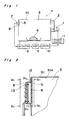
- a high-frequency heating apparatus K In the heating apparatus K, electromagnetic wave emitted from a high-frequency oscillator 1 is supplied, through a waveguide 2, into a high-frequency heating chamber 3 so as to heat a food 4 in a cabinet 30 having a shape of rectangular parallelepiped. Electromagnetic wave in the cabinet 30 is detected, via a dielectric plate 5 and an opening 6 of the cabinet 30, in direct current by a detector 8 provided with an antenna 7. The detector 8 has a grounded conductor whose one portion is connected to a wall of the cabinet 30. A current signal detected by the detector 8 is fed, through an amplifier 9, to a control circuit 10 leading to a power source circuit 11. Since the amplifier 9 is provided between the detector 8 and the control circuit 10, the power source circuit 11 can be controlled stably at a high signal level against noises.
- Fig. 2 and Figs. 3a to 3c show the opening 6 and the detector 8.
- the detector 8 is secured to a bracket 12 attached to an outer surface of the wall of the cabinet 30.
- the detector 8 is formed by a microstrip line including an active conductor 14 and grounded faces 15 and 16.
- the detector 8 further includes resistors 17, 18 and 19, a diode 20 and a capacitor 21.
- the grounded faces 15 and 16 are connected to each other by forming a through-hole or by a connecting conductor 22. Since the grounded face 16 is held in contact with the bracket 12, the grounded faces 15 and 16 of the microstrip line have a potential identical with that of the heating chamber 3, so that a microwave transmission circuit functioning stably is obtained.
- a conductor piece at the side of the grounded face 16 is connected to the active conductor 14 at the side of the grounded face 15 so as to act as the antenna 7.
- the dielectric plate 5 is fixed to an inner surface of the wall of the cabinet 30 by bonding agent, etc. so as to cover the opening 6. Therefore, the dielectric plate 5 confronts the antenna 7 through the opening 6 and prevents water and oil in the cabinet 30 from reaching the antenna 7 directly.
- Lead wires 24 and 25 are, respectively, attached to the active conductor 14 and the grounded face 15 by solder, etc. and are led to the amplifier 9.
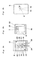
- the opening 6 is of a crossed shape having crossing portions 6a and 6b and the crossing portions 6a and 6b are inclined at an angle ⁇ relative to a horizontal direction of the cabinet 30 as shown in Fig. 3c.
- the heating chamber 3 defines a rectangular contour having a straight portion 30A, etc. in a plane at which the opening 6 confronts the dielectric plate 5. Therefore, the crossing portions 6a and 6b extend obliquely relative to the straight portion 30A of the contour and thus, the antenna 7 is least likely to be affected by mode change of standing wave in the heating chamber 3.
- the crossing portions 6a and 6b deviate from a longitudinal direction of the antenna 7 as shown in Figs. 3b and 3c, average whole change of dielectric loss in the heating chamber 3 can be received by the antenna 7.
- the opening 6 has a crossed shape.
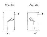
- the opening 6 is not restricted to the crossed shape but may have any elongated shape such as an opening 6' in Fig. 6a or an opening 6'' shown in Fig. 6b such that a longitudinal direction of the opening 6' or 6'' extends obliquely relative to the straight portion 30A of the contour.
- the longitudinal direction of the opening 6' or 6'' deviates from the longitudinal direction of the antenna 7.
- the opening 6 is formed in the side wall of the cabinet 30.
- the present invention can also be applied to an arrangement in which the opening 6 is formed in the top plate of the cabinet 30.
- Fig. 4 shows temperature characteristics of dielectric loss ( ⁇ r x tan ⁇ ) of beef or fish measured at a frequency of 2,400 MHz in the heating apparatus K. It is apparent from Fig. 4 that dielectric loss changes greatly among a frozen state, a defrozen state, a room temperature state and a heated state of the food. This phenomenon in which dielectric loss is great indicates that electromagnetic wave is well absorbed by the food.
- Fig. 5 shows one example of detection output in the case of heating beef from a frozen state in the heating apparatus K. From Figs. 4 and 5, it will be seen that when dielectric loss of the food is small, detection output is large. On the other hand, when dielectric loss of the food is large, detection output becomes small. Therefore, by controlling the power source circuit 11 on the basis of magnitude of detection output or trend of change of detection output, it becomes possible to automatically detect defreesing or heating of the food.
- the antenna is provided outside the heating chamber and electromagnetic wave from the opening of the cabinet is received through the dielectric plate so as to be detected. Furthermore, the grounded faces of the detector are connected to the heating chamber. Therefore, in accordance with the present invention, even if water or oil scatters from the food, such an undesirable phenomenon does not take place that the antenna is short-circuited to the grounded faces by water or oil of the food, so that stable control performance of the heating apparatus can be secured for a long term. Moreover, even if mass production of the heating apparatus is performed, the detector can function stably.
- the conductor piece of the printed circuit board which constitutes the detector formed by the microstrip line acts as the antenna, dimensional accuracy of the antenna is more excellent than an arrangement in which an antenna is provided outwardly of the printed circuit board or an arrangement in which a metallic rod acting as an antenna is vertically erected on the printed circuit board. Therefore, in accordance with the present invention, the antenna has stable microwave characteristics.
- the antenna is least likely to be affected by mode change of standing wave in the heating chamber. Therefore, in the detector of the present invention, average whole change of dielectric loss in the heating chamber can be received by the single antenna without the need for providing a plurality of the antennas.
- the amplifier is provided between the detector and the control circuit, the power source circuit can be controlled at a high signal level against noises.
Abstract
Description
- The present invention relates to a high-frequency heating apparatus such as an electronic range, in which a high-frequency heat source, e.g. a magnetron is controlled by detecting field intensity in a cabinet.
- A high-frequency heating apparatus is known from, for example, Japanese Patent Laid-Open Publication No. 59-207595 in which by using transmitting and receiving antennas confronting a heating chamber, changes of dielectric constant of an article to be heated (hereinbelow, referred to as a "food") dependent upon temperature of the food are detected so as to control a high-frequency heat source.
- However, the known high-frequency heating apparatus in which the antennas confront the heating chamber has such a drawback that especially at the time of heating of the food, a large amount of water or oil from the food scatters in the cabinet and penetrate into a contact point between the receiving antenna and a detector, thereby resulting in great change in detection characteristics.
- Accordingly, an essential object of the present invention is to provide a high-frequency heating apparatus in which an antenna is provided outside a heating chamber so as not to be contaminated by water or oil scattered from a food in the heating chamber.
- In order to accomplish this object of the present invention, a high-frequency heating apparatus according to the present invention comprises: a high-frequency oscillator for oscillating high-frequency electromagnetic wave by electric power supplied from a power source circuit; a heating chamber into which the high-frequency electromagnetic wave is supplied by said high-frequency oscillator; an antenna which is provided outside said heating chamber and adjacent to an opening of said heating chamber; a dielectric plate for covering the opening, which is provided in said heating chamber so as to confront said antenna through the opening; a detector which receives an output from said antenna and has a grounded portion such that said grounded portion is connected to said heating chamber; and a control circuit which receives an output from said detector so as to output a control signal to said power source circuit.
- This object and features of the present invention will become apparent from the following description taken in conjunction with the preferred embodiment thereof with reference to the accompanying drawings, in which:
- Fig. 1 is a schematic view of a high-frequency heating apparatus according to one embodiment of the present invention;
- Fig. 2 is a fragmentary sectional view of the heating apparatus of Fig. 1;
- Figs. 3a, 3b and 3c are views observed in the directions of the arrows IIIa-IIIa, IIIb-IIIb and IIIc-IIIc in Fig. 2, respectively;
- Fig. 4 is a graph showing temperature characteristics of dielectric loss of a food in the heating apparatus of Fig. 1;
- Fig. 5 is a graph showing wave form of detection output in the heating apparatus of Fig. 1; and
- Figs. 6a and 6b are views similar to Fig. 3c, particularly showing first and second modifications thereof, respectively.
- Before the description of the present invention proceeds, it is to be noted that like parts are designated by like reference numerals throughout the accompanying drawings.
- Referring now to the drawings, there is shown in Fig. 1, a high-frequency heating apparatus K according to one embodiment of the present invention. In the heating apparatus K, electromagnetic wave emitted from a high-
frequency oscillator 1 is supplied, through awaveguide 2, into a high-frequency heating chamber 3 so as to heat afood 4 in acabinet 30 having a shape of rectangular parallelepiped. Electromagnetic wave in thecabinet 30 is detected, via adielectric plate 5 and anopening 6 of thecabinet 30, in direct current by adetector 8 provided with anantenna 7. Thedetector 8 has a grounded conductor whose one portion is connected to a wall of thecabinet 30. A current signal detected by thedetector 8 is fed, through an amplifier 9, to a control circuit 10 leading to a power source circuit 11. Since the amplifier 9 is provided between thedetector 8 and the control circuit 10, the power source circuit 11 can be controlled stably at a high signal level against noises. - Fig. 2 and Figs. 3a to 3c show the opening 6 and the
detector 8. By usingmachine screws 13, thedetector 8 is secured to abracket 12 attached to an outer surface of the wall of thecabinet 30. Thedetector 8 is formed by a microstrip line including anactive conductor 14 andgrounded faces detector 8 further includesresistors diode 20 and acapacitor 21. Thegrounded faces conductor 22. Since thegrounded face 16 is held in contact with thebracket 12, thegrounded faces heating chamber 3, so that a microwave transmission circuit functioning stably is obtained. By using another connectingconductor 23, a conductor piece at the side of thegrounded face 16 is connected to theactive conductor 14 at the side of thegrounded face 15 so as to act as theantenna 7. Thedielectric plate 5 is fixed to an inner surface of the wall of thecabinet 30 by bonding agent, etc. so as to cover theopening 6. Therefore, thedielectric plate 5 confronts theantenna 7 through the opening 6 and prevents water and oil in thecabinet 30 from reaching theantenna 7 directly.Lead wires active conductor 14 and thegrounded face 15 by solder, etc. and are led to the amplifier 9. - The opening 6 is of a crossed shape having crossing
portions crossing portions cabinet 30 as shown in Fig. 3c. Meanwhile, as shown in Fig. 2, theheating chamber 3 defines a rectangular contour having astraight portion 30A, etc. in a plane at which theopening 6 confronts thedielectric plate 5. Therefore, thecrossing portions straight portion 30A of the contour and thus, theantenna 7 is least likely to be affected by mode change of standing wave in theheating chamber 3. As a result, average whole change of dielectric loss in theheating chamber 3 can be received by thesingle antenna 7 without the need for providing a plurality of the antennas. Meanwhile, since thecrossing portions antenna 7 as shown in Figs. 3b and 3c, average whole change of dielectric loss in theheating chamber 3 can be received by theantenna 7. - Meanwhile, in the above embodiment, the opening 6 has a crossed shape. However, the
opening 6 is not restricted to the crossed shape but may have any elongated shape such as an opening 6' in Fig. 6a or an opening 6'' shown in Fig. 6b such that a longitudinal direction of the opening 6' or 6'' extends obliquely relative to thestraight portion 30A of the contour. Likewise, the longitudinal direction of the opening 6' or 6'' deviates from the longitudinal direction of theantenna 7. - Furthermore, in the above embodiment, the
opening 6 is formed in the side wall of thecabinet 30. However, the present invention can also be applied to an arrangement in which theopening 6 is formed in the top plate of thecabinet 30. - Fig. 4 shows temperature characteristics of dielectric loss (εr x tanδ) of beef or fish measured at a frequency of 2,400 MHz in the heating apparatus K. It is apparent from Fig. 4 that dielectric loss changes greatly among a frozen state, a defrozen state, a room temperature state and a heated state of the food. This phenomenon in which dielectric loss is great indicates that electromagnetic wave is well absorbed by the food.
- Fig. 5 shows one example of detection output in the case of heating beef from a frozen state in the heating apparatus K. From Figs. 4 and 5, it will be seen that when dielectric loss of the food is small, detection output is large. On the other hand, when dielectric loss of the food is large, detection output becomes small. Therefore, by controlling the power source circuit 11 on the basis of magnitude of detection output or trend of change of detection output, it becomes possible to automatically detect defreesing or heating of the food.
- As is clear from the foregoing, in the heating apparatus of the present invention, the antenna is provided outside the heating chamber and electromagnetic wave from the opening of the cabinet is received through the dielectric plate so as to be detected. Furthermore, the grounded faces of the detector are connected to the heating chamber. Therefore, in accordance with the present invention, even if water or oil scatters from the food, such an undesirable phenomenon does not take place that the antenna is short-circuited to the grounded faces by water or oil of the food, so that stable control performance of the heating apparatus can be secured for a long term. Moreover, even if mass production of the heating apparatus is performed, the detector can function stably.
- Meanwhile, since the conductor piece of the printed circuit board which constitutes the detector formed by the microstrip line acts as the antenna, dimensional accuracy of the antenna is more excellent than an arrangement in which an antenna is provided outwardly of the printed circuit board or an arrangement in which a metallic rod acting as an antenna is vertically erected on the printed circuit board. Therefore, in accordance with the present invention, the antenna has stable microwave characteristics.
- In addition, by using a frequency filter circuit based on the microstrip line constituted by the printed circuit board, electric parts for the detector such as the resistors, the diode and the capacitor may function at a relatively low frequency, so that the detector can be produced at low cost and stably.
- Meanwhile, since the longitudinal direction of the opening extends obliquely relative to the straight portion of the contour defined by the heating chamber in the plane at which the opening confronts the dielectric plate, the antenna is least likely to be affected by mode change of standing wave in the heating chamber. Therefore, in the detector of the present invention, average whole change of dielectric loss in the heating chamber can be received by the single antenna without the need for providing a plurality of the antennas.
- Furthermore, since the longitudinal direction of the opening deviates from the longitudinal direction of the antenna, average whole change of dielectric loss in the heating chamber can be received by the antenna.
- Moreover, since the amplifier is provided between the detector and the control circuit, the power source circuit can be controlled at a high signal level against noises.
- Although the present invention has been fully described by way of example with reference to the accompanying drawings, it is to be noted here that various changes and modifications will be apparent to those skilled in the art. Therefore, unless otherwise such changes and modifications depart from the scope of the present invention, they should be construed as being included therein.
Claims (5)
- A high-frequency heating apparatus (K) comprising:
a high-frequency oscillator (1) for oscillating high-frequency electromagnetic wave by electric power supplied from a power source circuit (11);
a heating chamber (3) into which the high-frequency electromagnetic wave is supplied by said high-frequency oscillator (1);
an antenna (7) which is provided outside said heating chamber (3) and adjacent to an opening (6) of said heating chamber (3);
a dielectric plate (5) for covering the opening (6), which is provided in said heating chamber (3) so as to confront said antenna (7) through the opening (6);
a detector (8) which receives an output from said antenna (7) and has a grounded portion (15, 16) such that said grounded portion (15, 16) is connected to said heating chamber (3); and
a control circuit (10) which receives an output from said detector (8) so as to output a control signal to said power source circuit (11). - A high-frequency heating apparatus (K) as claimed in Claim 1, wherein said detector is formed by a printed circuit board such that a conductor piece of said printed circuit board acts as said antenna (7).
- A high-frequency heating apparatus (K) as claimed in Claim 1, wherein the opening (6) has an elongated shape and said heating chamber (3) defines, in a plane at which the opening (6) confronts said dielectric plate (5), a contour having a straight portion (30A) such that a longitudinal direction of the opening (6) extends obliquely relative to the straight portion (30A) of the contour.
- A high-frequency heating apparatus (K) as claimed in Claim 1, wherein the opening (6) has an elongated shape and a longitudinal direction of the opening (6) deviates from a longitudinal direction of said antenna (7).
- A high-frequency heating apparatus (K) as claimed in Claim 1, further comprising:
an amplifier (9) which is provided between said detector (8) and said control circuit (10).
Applications Claiming Priority (2)
| Application Number | Priority Date | Filing Date | Title |
|---|---|---|---|
| JP144747/90 | 1990-06-01 | ||
| JP2144747A JP2797657B2 (en) | 1990-06-01 | 1990-06-01 | High frequency heating equipment |
Publications (3)
| Publication Number | Publication Date |
|---|---|
| EP0459305A2 true EP0459305A2 (en) | 1991-12-04 |
| EP0459305A3 EP0459305A3 (en) | 1993-01-20 |
| EP0459305B1 EP0459305B1 (en) | 1997-09-03 |
Family
ID=15369430
Family Applications (1)
| Application Number | Title | Priority Date | Filing Date |
|---|---|---|---|
| EP91108386A Expired - Lifetime EP0459305B1 (en) | 1990-06-01 | 1991-05-24 | High-frequency heating apparatus |
Country Status (8)
| Country | Link |
|---|---|
| US (1) | US5171947A (en) |
| EP (1) | EP0459305B1 (en) |
| JP (1) | JP2797657B2 (en) |
| KR (1) | KR960006440B1 (en) |
| AU (1) | AU621783B2 (en) |
| BR (1) | BR9102237A (en) |
| CA (1) | CA2043436C (en) |
| DE (1) | DE69127499T2 (en) |
Cited By (2)
| Publication number | Priority date | Publication date | Assignee | Title |
|---|---|---|---|---|
| DE4207459A1 (en) * | 1992-03-10 | 1993-09-23 | Miele & Cie | Microwave oven with load condition sensor - has magnetron giving electromagnetic power for heating food in cooking chamber and determines output density of electromagnetic field using load condition sensor |
| EP2663160A1 (en) * | 2012-05-10 | 2013-11-13 | Miele & Cie. KG | Domestic appliance |
Families Citing this family (7)
| Publication number | Priority date | Publication date | Assignee | Title |
|---|---|---|---|---|
| US5254819A (en) * | 1989-12-29 | 1993-10-19 | Matsushita Electric Industrial Co., Ltd. | High-frequency heating apparatus with copper for grounding layer surrounding electromagnetic wave antenna |
| AU628266B2 (en) * | 1990-07-17 | 1992-09-10 | Matsushita Electric Industrial Co., Ltd. | High frequency heating apparatus |
| CA2087638C (en) * | 1992-01-23 | 1997-02-25 | Masatugu Fukui | Microwave oven having a function for matching impedance |
| JP3106385B2 (en) | 1994-11-28 | 2000-11-06 | 株式会社村田製作所 | High frequency detecting element and high frequency heating device using the same |
| US6867402B1 (en) | 2004-04-08 | 2005-03-15 | Maytag Corporation | System for sensing the presence of a load in an oven cavity of a microwave cooking appliance |
| CN102331007A (en) * | 2011-06-22 | 2012-01-25 | 太仓南极风能源设备有限公司 | Scattering microwave oven |
| CN105679698B (en) | 2016-04-21 | 2018-09-18 | 京东方科技集团股份有限公司 | Substrate board treatment |
Citations (7)
| Publication number | Priority date | Publication date | Assignee | Title |
|---|---|---|---|---|
| US3875361A (en) * | 1972-06-16 | 1975-04-01 | Hitachi Ltd | Microwave heating apparatus having automatic heating period control |
| JPS55113919A (en) * | 1979-02-23 | 1980-09-02 | Matsushita Electric Ind Co Ltd | High frequency heater |
| EP0098402A1 (en) * | 1982-06-11 | 1984-01-18 | Kabushiki Kaisha Toshiba | Temperature measuring apparatus |
| JPS60171318A (en) * | 1984-02-16 | 1985-09-04 | Matsushita Electric Ind Co Ltd | Cooking apparatus with infrared ray sensor |
| JPS6358024A (en) * | 1986-08-27 | 1988-03-12 | Toshiba Corp | Electronic oven |
| JPH01305228A (en) * | 1988-06-02 | 1989-12-08 | Hitachi Heating Appliance Co Ltd | Cooking apparatus |
| EP0461269A1 (en) * | 1989-12-29 | 1991-12-18 | Matsushita Electric Industrial Co., Ltd. | High-frequency heating device |
Family Cites Families (14)
| Publication number | Priority date | Publication date | Assignee | Title |
|---|---|---|---|---|
| US2704802A (en) * | 1952-05-22 | 1955-03-22 | Raytheon Mfg Co | Microwave ovens |
| JPS5251133A (en) * | 1975-10-21 | 1977-04-23 | Hitachi Heating Appliance Co Ltd | High-frequency heating device |
| US4297557A (en) * | 1976-05-03 | 1981-10-27 | Robertshaw Controls Company | Microwave oven temperature indicator and control means |
| JPS5349347A (en) * | 1976-10-18 | 1978-05-04 | Hitachi Heating Appliance Co Ltd | Microwave oven |
| JPS542541A (en) * | 1977-06-08 | 1979-01-10 | Hitachi Heating Appliance Co Ltd | High frequency heating device |
| JPS5413037A (en) * | 1977-06-29 | 1979-01-31 | Hitachi Heating Appliance Co Ltd | High frequency wave heating device |
| US4162381A (en) * | 1977-08-30 | 1979-07-24 | Litton Systems, Inc. | Microwave oven sensing system |
| GB2117925B (en) * | 1982-02-19 | 1986-02-05 | Hitachi Heating Appl | Heating apparatus of thawing sensor controlled type |
| JPS59207595A (en) * | 1983-05-10 | 1984-11-24 | 株式会社日立ホームテック | High frequency heater |
| AU551298B2 (en) * | 1984-02-07 | 1986-04-24 | Matsushita Electric Industrial Co., Ltd. | High frequency heating apparatus |
| JPS62154593A (en) * | 1985-12-27 | 1987-07-09 | 株式会社東芝 | Cooker |
| EP0264935B1 (en) * | 1986-10-22 | 1992-04-22 | Matsushita Electric Industrial Co., Ltd. | Automatic heating appliance with ultrasonic sensor |
| SE458493B (en) * | 1987-01-08 | 1989-04-03 | Philips Norden Ab | MIKROVAAGSUGN |
| JPH01246787A (en) * | 1988-03-28 | 1989-10-02 | Toshiba Corp | Cooking apparatus |
-
1990
- 1990-06-01 JP JP2144747A patent/JP2797657B2/en not_active Expired - Fee Related
-
1991
- 1991-05-22 AU AU77176/91A patent/AU621783B2/en not_active Ceased
- 1991-05-22 US US07/704,182 patent/US5171947A/en not_active Expired - Lifetime
- 1991-05-24 DE DE69127499T patent/DE69127499T2/en not_active Expired - Fee Related
- 1991-05-24 EP EP91108386A patent/EP0459305B1/en not_active Expired - Lifetime
- 1991-05-29 CA CA002043436A patent/CA2043436C/en not_active Expired - Lifetime
- 1991-05-29 KR KR1019910008773A patent/KR960006440B1/en not_active IP Right Cessation
- 1991-05-31 BR BR919102237A patent/BR9102237A/en not_active IP Right Cessation
Patent Citations (7)
| Publication number | Priority date | Publication date | Assignee | Title |
|---|---|---|---|---|
| US3875361A (en) * | 1972-06-16 | 1975-04-01 | Hitachi Ltd | Microwave heating apparatus having automatic heating period control |
| JPS55113919A (en) * | 1979-02-23 | 1980-09-02 | Matsushita Electric Ind Co Ltd | High frequency heater |
| EP0098402A1 (en) * | 1982-06-11 | 1984-01-18 | Kabushiki Kaisha Toshiba | Temperature measuring apparatus |
| JPS60171318A (en) * | 1984-02-16 | 1985-09-04 | Matsushita Electric Ind Co Ltd | Cooking apparatus with infrared ray sensor |
| JPS6358024A (en) * | 1986-08-27 | 1988-03-12 | Toshiba Corp | Electronic oven |
| JPH01305228A (en) * | 1988-06-02 | 1989-12-08 | Hitachi Heating Appliance Co Ltd | Cooking apparatus |
| EP0461269A1 (en) * | 1989-12-29 | 1991-12-18 | Matsushita Electric Industrial Co., Ltd. | High-frequency heating device |
Non-Patent Citations (4)
| Title |
|---|
| PATENT ABSTRACTS OF JAPAN vol. 004, no. 168 (P-037) 20 November 1980 & JP 55 113919 A (MATSUSHITA) 02 September 1980 * |
| PATENT ABSTRACTS OF JAPAN vol. 010, no. 006 (M-445) 11 January 1986 & JP 60 171318 A (MATSUSHITA) 04 September 1985 * |
| PATENT ABSTRACTS OF JAPAN vol. 012, no. 282 (M-726) 03 August 1988 & JP 63 058024 A (TOSHIBA) 12 March 1988 * |
| PATENT ABSTRACTS OF JAPAN vol. 014, no. 097 (M-940) 22 February 1990 & JP 01 305228 A (HITACHI) 08 December 1989 * |
Cited By (2)
| Publication number | Priority date | Publication date | Assignee | Title |
|---|---|---|---|---|
| DE4207459A1 (en) * | 1992-03-10 | 1993-09-23 | Miele & Cie | Microwave oven with load condition sensor - has magnetron giving electromagnetic power for heating food in cooking chamber and determines output density of electromagnetic field using load condition sensor |
| EP2663160A1 (en) * | 2012-05-10 | 2013-11-13 | Miele & Cie. KG | Domestic appliance |
Also Published As
| Publication number | Publication date |
|---|---|
| JPH0436991A (en) | 1992-02-06 |
| EP0459305B1 (en) | 1997-09-03 |
| DE69127499T2 (en) | 1998-01-08 |
| AU7717691A (en) | 1991-12-05 |
| KR920001136A (en) | 1992-01-30 |
| KR960006440B1 (en) | 1996-05-15 |
| CA2043436C (en) | 1996-11-05 |
| JP2797657B2 (en) | 1998-09-17 |
| US5171947A (en) | 1992-12-15 |
| DE69127499D1 (en) | 1997-10-09 |
| CA2043436A1 (en) | 1991-12-02 |
| AU621783B2 (en) | 1992-03-19 |
| BR9102237A (en) | 1992-01-07 |
| EP0459305A3 (en) | 1993-01-20 |
Similar Documents
| Publication | Publication Date | Title |
|---|---|---|
| EP0459305A2 (en) | High-frequency heating apparatus | |
| CN107926090B (en) | Core temperature probe, microwave cooking device and system | |
| EP0461269B1 (en) | High-frequency heating device | |
| US5394154A (en) | High-frequency signal generator and radar module | |
| US5237141A (en) | High frequency heating apparatus and electromagnetic wave detector for use in high frequency heating apparatus | |
| EP0467224B1 (en) | High frequency heating apparatus and electromagnetic wave detector for use in high frequency heating apparatus | |
| JP3051139B2 (en) | High frequency heating equipment | |
| US5717400A (en) | High-frequency signal generator and radar module | |
| EP1021069A2 (en) | Microwave oven with magnetic field sensor | |
| US3859657A (en) | Second harmonic filter for high frequency source | |
| JPH07131235A (en) | Slot antenna with dielectric resonator | |
| CN112379361B (en) | Planar microwave sensor | |
| JP2897361B2 (en) | High frequency heating equipment | |
| JP2563571B2 (en) | High frequency heating equipment | |
| JPH0471188A (en) | High frequency heating device | |
| KR940007229B1 (en) | Automatic cooking apparatus of a range | |
| JP3051140B2 (en) | High frequency heating equipment | |
| JPH03156882A (en) | High-frequency heating device | |
| KR100186419B1 (en) | Microwave oven having a defrosting sensor | |
| JP2699618B2 (en) | High frequency heating equipment | |
| JPH07120546A (en) | Doppler module | |
| JP2563602B2 (en) | High frequency heating equipment | |
| CA2046775C (en) | High frequency heating apparatus and electromagnetic wave detector for use in high frequency heating apparatus | |
| JPH03204516A (en) | High-frequency heater | |
| JPH02183992A (en) | High-frequency heating device |
Legal Events
| Date | Code | Title | Description |
|---|---|---|---|
| PUAI | Public reference made under article 153(3) epc to a published international application that has entered the european phase |
Free format text: ORIGINAL CODE: 0009012 |
|
| 17P | Request for examination filed |
Effective date: 19910524 |
|
| AK | Designated contracting states |
Kind code of ref document: A2 Designated state(s): DE FR GB IT SE |
|
| PUAL | Search report despatched |
Free format text: ORIGINAL CODE: 0009013 |
|
| AK | Designated contracting states |
Kind code of ref document: A3 Designated state(s): DE FR GB IT SE |
|
| 17Q | First examination report despatched |
Effective date: 19950614 |
|
| GRAG | Despatch of communication of intention to grant |
Free format text: ORIGINAL CODE: EPIDOS AGRA |
|
| GRAH | Despatch of communication of intention to grant a patent |
Free format text: ORIGINAL CODE: EPIDOS IGRA |
|
| GRAH | Despatch of communication of intention to grant a patent |
Free format text: ORIGINAL CODE: EPIDOS IGRA |
|
| GRAA | (expected) grant |
Free format text: ORIGINAL CODE: 0009210 |
|
| AK | Designated contracting states |
Kind code of ref document: B1 Designated state(s): DE FR GB IT SE |
|
| ITF | It: translation for a ep patent filed |
Owner name: JACOBACCI & PERANI S.P.A. |
|
| REF | Corresponds to: |
Ref document number: 69127499 Country of ref document: DE Date of ref document: 19971009 |
|
| ET | Fr: translation filed | ||
| PLBE | No opposition filed within time limit |
Free format text: ORIGINAL CODE: 0009261 |
|
| STAA | Information on the status of an ep patent application or granted ep patent |
Free format text: STATUS: NO OPPOSITION FILED WITHIN TIME LIMIT |
|
| 26N | No opposition filed | ||
| REG | Reference to a national code |
Ref country code: GB Ref legal event code: IF02 |
|
| PGFP | Annual fee paid to national office [announced via postgrant information from national office to epo] |
Ref country code: DE Payment date: 20090527 Year of fee payment: 19 Ref country code: FR Payment date: 20090515 Year of fee payment: 19 Ref country code: IT Payment date: 20090520 Year of fee payment: 19 Ref country code: SE Payment date: 20090512 Year of fee payment: 19 |
|
| PGFP | Annual fee paid to national office [announced via postgrant information from national office to epo] |
Ref country code: GB Payment date: 20090520 Year of fee payment: 19 |
|
| GBPC | Gb: european patent ceased through non-payment of renewal fee |
Effective date: 20100524 |
|
| EUG | Se: european patent has lapsed | ||
| REG | Reference to a national code |
Ref country code: FR Ref legal event code: ST Effective date: 20110131 |
|
| PG25 | Lapsed in a contracting state [announced via postgrant information from national office to epo] |
Ref country code: IT Free format text: LAPSE BECAUSE OF NON-PAYMENT OF DUE FEES Effective date: 20100524 Ref country code: SE Free format text: LAPSE BECAUSE OF NON-PAYMENT OF DUE FEES Effective date: 20100525 |
|
| PG25 | Lapsed in a contracting state [announced via postgrant information from national office to epo] |
Ref country code: DE Free format text: LAPSE BECAUSE OF NON-PAYMENT OF DUE FEES Effective date: 20101201 |
|
| PG25 | Lapsed in a contracting state [announced via postgrant information from national office to epo] |
Ref country code: FR Free format text: LAPSE BECAUSE OF NON-PAYMENT OF DUE FEES Effective date: 20100531 |
|
| PG25 | Lapsed in a contracting state [announced via postgrant information from national office to epo] |
Ref country code: GB Free format text: LAPSE BECAUSE OF NON-PAYMENT OF DUE FEES Effective date: 20100524 |