EP0458114B1 - Pompe à pistons radiaux - Google Patents
Pompe à pistons radiaux Download PDFInfo
- Publication number
- EP0458114B1 EP0458114B1 EP91107270A EP91107270A EP0458114B1 EP 0458114 B1 EP0458114 B1 EP 0458114B1 EP 91107270 A EP91107270 A EP 91107270A EP 91107270 A EP91107270 A EP 91107270A EP 0458114 B1 EP0458114 B1 EP 0458114B1
- Authority
- EP
- European Patent Office
- Prior art keywords
- pump
- cam
- actuating
- radial piston
- fluid
- Prior art date
- Legal status (The legal status is an assumption and is not a legal conclusion. Google has not performed a legal analysis and makes no representation as to the accuracy of the status listed.)
- Expired - Lifetime
Links
- 239000012530 fluid Substances 0.000 claims abstract description 104
- 238000007789 sealing Methods 0.000 claims description 17
- 230000005489 elastic deformation Effects 0.000 claims description 6
- 230000007704 transition Effects 0.000 claims description 4
- 230000008878 coupling Effects 0.000 claims description 3
- 238000010168 coupling process Methods 0.000 claims description 3
- 238000005859 coupling reaction Methods 0.000 claims description 3
- 230000009469 supplementation Effects 0.000 claims 1
- 239000007788 liquid Substances 0.000 description 20
- 239000011324 bead Substances 0.000 description 13
- 238000010586 diagram Methods 0.000 description 5
- 238000000034 method Methods 0.000 description 5
- 230000008569 process Effects 0.000 description 5
- 238000010276 construction Methods 0.000 description 3
- 238000006073 displacement reaction Methods 0.000 description 3
- 239000000463 material Substances 0.000 description 2
- 230000008901 benefit Effects 0.000 description 1
- 230000008859 change Effects 0.000 description 1
- 238000004891 communication Methods 0.000 description 1
- 238000007906 compression Methods 0.000 description 1
- 238000001802 infusion Methods 0.000 description 1
- 238000001746 injection moulding Methods 0.000 description 1
- 239000002184 metal Substances 0.000 description 1
- 229920002379 silicone rubber Polymers 0.000 description 1
- 239000004945 silicone rubber Substances 0.000 description 1
Images


Classifications
-
- F—MECHANICAL ENGINEERING; LIGHTING; HEATING; WEAPONS; BLASTING
- F04—POSITIVE - DISPLACEMENT MACHINES FOR LIQUIDS; PUMPS FOR LIQUIDS OR ELASTIC FLUIDS
- F04B—POSITIVE-DISPLACEMENT MACHINES FOR LIQUIDS; PUMPS
- F04B1/00—Multi-cylinder machines or pumps characterised by number or arrangement of cylinders
- F04B1/04—Multi-cylinder machines or pumps characterised by number or arrangement of cylinders having cylinders in star- or fan-arrangement
- F04B1/047—Multi-cylinder machines or pumps characterised by number or arrangement of cylinders having cylinders in star- or fan-arrangement with actuating or actuated elements at the outer ends of the cylinders
- F04B1/0472—Multi-cylinder machines or pumps characterised by number or arrangement of cylinders having cylinders in star- or fan-arrangement with actuating or actuated elements at the outer ends of the cylinders with cam-actuated distribution members
-
- F—MECHANICAL ENGINEERING; LIGHTING; HEATING; WEAPONS; BLASTING
- F04—POSITIVE - DISPLACEMENT MACHINES FOR LIQUIDS; PUMPS FOR LIQUIDS OR ELASTIC FLUIDS
- F04B—POSITIVE-DISPLACEMENT MACHINES FOR LIQUIDS; PUMPS
- F04B1/00—Multi-cylinder machines or pumps characterised by number or arrangement of cylinders
- F04B1/04—Multi-cylinder machines or pumps characterised by number or arrangement of cylinders having cylinders in star- or fan-arrangement
- F04B1/0404—Details or component parts
- F04B1/0413—Cams
-
- F—MECHANICAL ENGINEERING; LIGHTING; HEATING; WEAPONS; BLASTING
- F04—POSITIVE - DISPLACEMENT MACHINES FOR LIQUIDS; PUMPS FOR LIQUIDS OR ELASTIC FLUIDS
- F04B—POSITIVE-DISPLACEMENT MACHINES FOR LIQUIDS; PUMPS
- F04B11/00—Equalisation of pulses, e.g. by use of air vessels; Counteracting cavitation
- F04B11/005—Equalisation of pulses, e.g. by use of air vessels; Counteracting cavitation using two or more pumping pistons
- F04B11/0058—Equalisation of pulses, e.g. by use of air vessels; Counteracting cavitation using two or more pumping pistons with piston speed control
- F04B11/0066—Equalisation of pulses, e.g. by use of air vessels; Counteracting cavitation using two or more pumping pistons with piston speed control with special shape of the actuating element
-
- F—MECHANICAL ENGINEERING; LIGHTING; HEATING; WEAPONS; BLASTING
- F04—POSITIVE - DISPLACEMENT MACHINES FOR LIQUIDS; PUMPS FOR LIQUIDS OR ELASTIC FLUIDS
- F04B—POSITIVE-DISPLACEMENT MACHINES FOR LIQUIDS; PUMPS
- F04B7/00—Piston machines or pumps characterised by having positively-driven valving
-
- F—MECHANICAL ENGINEERING; LIGHTING; HEATING; WEAPONS; BLASTING
- F04—POSITIVE - DISPLACEMENT MACHINES FOR LIQUIDS; PUMPS FOR LIQUIDS OR ELASTIC FLUIDS
- F04B—POSITIVE-DISPLACEMENT MACHINES FOR LIQUIDS; PUMPS
- F04B9/00—Piston machines or pumps characterised by the driving or driven means to or from their working members
- F04B9/02—Piston machines or pumps characterised by the driving or driven means to or from their working members the means being mechanical
- F04B9/04—Piston machines or pumps characterised by the driving or driven means to or from their working members the means being mechanical the means being cams, eccentrics or pin-and-slot mechanisms
- F04B9/047—Piston machines or pumps characterised by the driving or driven means to or from their working members the means being mechanical the means being cams, eccentrics or pin-and-slot mechanisms the means being pin-and-slot mechanisms
Definitions
- the invention relates to a radial piston pump with a bellhousing, in which two pump chambers lying on a straight line are formed, in which there are pump pistons which can be moved back and forth on the straight line and which, when a driving part rotates relative to the bellhousing about a line intersecting the straight line and the axis of rotation lying centrally between the pump chambers are moved, with at least one fluid channel being connected to each of the pump chambers at its end closer to the axis of rotation, which is closed as a function of the relative position of the driver part and the pump carrier.
- a known radial piston pump of this type (DE-A-36 15 885), which is to be used as a gas compressor, there are two pairs of pump chambers in the cruciform pump support, each pair lying on a straight line, the two straight lines being perpendicular cut in the axis of rotation.
- the rear ends of the pump pistons in the pump chambers are in engagement with a guide which is formed by a housing which rotates about the axis of rotation, so that the pump pistons on the straight line when the housing acting as a driving part rotates around the pump carrier in the pump chambers. and are moved, whereby the pump pistons of a pair are both moved outwards at the same time or both inwards at the same time, that is to say the pump pistons lying on a common straight line move in the same direction.
- fluid channels adjoin, which extend parallel to the axis of rotation up to one side of the pump support, while openings are formed in the housing on the same radius, which are in a specific rotational position in alignment with the fluid channels. These openings serve to allow gas to enter the pump chambers through the fluid channels and to allow compressed gas to exit from them, while the compression process is carried out with fluid channels covered by the housing.
- This known radial piston pump is only suitable as a compressor since there is only a single fluid channel for each pump chamber.
- the seal in the area of the fluid channels is extremely poor because it is caused only by the circumferential housing wall, the transition between the closed fluid channel and the fully open fluid channel being effected by a gradual change in the opening cross section of the fluid channel, which leads to a very uneven flow - and funding process leads.
- a radial piston pump is also already known (GB-A-272 955), in which a plurality of pump chambers are present in a pump carrier, in which pump pistons are moved back and forth, each pump chamber being connected to a suction fluid channel and to a discharge fluid channel is in the course of which a valve arrangement is provided, which cooperate with actuating devices provided on the driver part.
- the intake fluid channels are connected to a common main intake channel.
- the longitudinal axes of the pump chambers in the direction of which the pump pistons move back and forth, are tangentially placed on a circle which is coaxial to the axis of rotation about which the bellhousing rotates with respect to a driver part coupled to the pump piston, but in one distance from the axis of rotation determined by the diameter of the circle.
- the tangential arrangement of the longitudinal axes of the pump chambers is intended to support the rotary movement of the bellhousing.
- a radial piston pump of the type mentioned is designed according to the invention in such a way that the pump pistons are reciprocally moved back and forth by coupling with a driver part, such that each pump chamber is connected to an intake fluid channel and an exhaust fluid channel, in the latter
- a valve arrangement is provided in each case, which cooperate with actuating devices provided on the driver part, and that the intake fluid channels are connected to a common main intake channel and the exhaust fluid channels are connected to a common main exhaust channel.
- the pump pistons lying on the straight line are moved in opposite directions, so that fluid is sucked into one pump chamber via its suction fluid channel, while fluid is expelled from the other pump chamber via its discharge fluid channel, as a result of which fluid is continuously conveyed at a given rate.
- the fluid for both intake fluid channels is made from this sucked common main suction channel and fed from the two discharge fluid channels to the common main discharge channel.
- valve arrangements for the intake fluid ducts and the discharge fluid ducts takes place in a precisely controlled manner, since the driver part, which causes the positively guided movement of the pump pistons by rotation about the axis of rotation, also with the actuating devices provided on it, the valve arrangements for the Brings fluid channels in an open and in a closed state.
- the movements of the pump pistons and the control of the valve arrangements for the fluid channels are carried out synchronously with one another in a precisely predetermined manner, so that the fluid delivery takes place in a completely reproducible manner in the predetermined manner.
- the driver part has at least one control disk rotatable about the axis of rotation, which carries at least one driver cam for a pump piston and on which an actuating device for at least the valve arrangements in the intake fluid channel of one pump chamber and in the exhaust fluid channel of the other pump chamber is provided.
- a single control disk thus serves to move the one pump piston and to actuate two valve arrangements, it being also possible to provide the driver curves for both pump pistons on this control disk and, if appropriate, also to form the actuating devices for all valve arrangements on it.
- a control disk with a driver curve for a pump piston and an actuating device for the valve arrangements of an intake fluid channel and an exhaust fluid channel is arranged on one side of the pump carrier, a corresponding control disk with a driver curve for the other pump piston and with an actuating device for the other valve arrangements on the opposite side of the bellhousing and also be fastened on the axis of rotation, so that the driver part consists of two firmly connected control disks lying on both sides of the bellhousing, which can be easily manufactured and assembled.
- the actuating devices can each have an elastically deformable actuating element which is non-rotatably held on the bellhousing, on the ends of which actuating projections are provided on the side facing the bellhousing for acting on the associated valve arrangement, while the side of the actuating element facing away from the bellhousing engages with cam surfaces formed on the control disk is feasible.
- a single actuating element held non-rotatably on the bellhousing serves to activate the valve arrangements, for which purpose cam surfaces provided on the control disk act on the actuating element.
- cam surfaces provided on the control disk act on the actuating element.
- actuating cams can be provided on the side of the actuating element facing away from the bellhousing, and the cam surface can bring about an elastic deformation of the actuating element for engaging an actuating projection by engagement with an actuating cam.
- a circular arc-shaped addition to the cam surface can consist of a recess for receiving the actuating cams, at the ends of which there are transitions to the cam surface forming ramps, so that the actuating cam-bearing region of the actuating element is undeformed when the actuating cam is located within the recess.
- the actuating cam can slide over the corresponding ramp for the transition from depression to cam surface and back.
- a laterally projecting cam pin can be provided on each pump piston, which is in engagement with the associated driver curve of the control disk.
- each fluid channel can have a lateral opening and be surrounded in this area by a flexible sealing hose.
- the actuating element for closing the valve arrangement can press the part of the sealing tube located in the area of the opening through the lateral opening into sealing contact on the wall of the fluid channel opposite it, in order in this way to close the fluid channel.
- the wall opposite the opening can be formed by an annular region which surrounds a section of the fluid channel running perpendicular to the central axis of the opening.
- the sealing tube can be pressed in a sealing manner against this ring region in order to securely close the section of the fluid channel that runs perpendicular to the central axis of the opening.
- the structure can be simplified by both Openings of both intake fluid channels and the openings of both discharge fluid channels are each coaxial with one another and the sections running perpendicular to the central axis of the opening are connected to one another, the associated main channel being connected to these connections.
- both intake fluid channels can be covered with a single sealing tube or sealing tube section and the openings of both discharge fluid channels can be covered with another sealing tube or sealing tube section.
- one suction fluid channel and one discharge fluid channel can be sealed alternately, while the other two fluid channels are kept open, so that liquid is sucked from the main suction channel into the associated pump chamber through the opened suction fluid channel, while liquid is forced out of the other pump chamber through the opened discharge fluid channel to the main discharge channel.
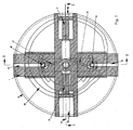
- the radial piston pump shown in FIGS. 1 to 4 has a cruciform pump support 1 with a central opening 48 (FIG. 4), the central axis of which coincides with the axis of rotation 50 to be described.
- pump chambers 10, 11 are formed on a straight line perpendicular to the axis of the central opening 48 and intersecting the axis 51, which are located on opposite sides of the axis of the central opening 48 and at the same distance from it.
- Pump pistons 4, 5 are inserted into the pump chambers 10, 11, which have sealing lips, not shown in more detail at their front ends, which are indicated in FIGS. 1 and 2.
- cam pins 6, 7 and 8, 9 are formed on the rear ends of the pump pistons 4, 5 and extend into guide slots 53, 54 in the pump bracket 1, which are open at their radially outer ends, the cam pins 6 , 7 and 8, 9 protrude somewhat beyond the bellhousing 1 in the direction of their longitudinal extent, as can be seen in particular in FIG.
- a main suction channel 13 is formed in one of the sections offset by 90 ° relative to the pump chambers 10, 11 of the cruciform pump bracket 1 and a main discharge channel 12 is formed in the other section offset by 90 °.
- These sections of the pump support 1 can be connected to a liquid supply with appropriate hose or tubular connections or can be connected to a liquid receiver, these sections also being able to serve to hold the pump support on a support plate, also not shown, by means of a frame, not shown.
- Fluid ducts run from the bottoms of the pump chamber 10, 11 near the central opening 48 to the main ducts 12 and 13, specifically from the pump chamber 10 an intake fluid duct 17 to the main intake duct 13 and an exhaust fluid duct 14 to the main exhaust duct 12 and from the bottom of the pump chamber 11 an intake fluid passage 15 to the main intake passage 13 and an exhaust fluid passage 16 to the main discharge passage 12.
- each of these annular channels forms an annular bead so that the annular bead 29 and the annular bead 27 surround the openings at the ends of the section 19 and the annular bead 26 and the annular bead 28 surround the openings at the ends of the section 18.
- cross-shaped bellhousing 1 can be produced very easily from plastic by injection molding and can thus be manufactured in large numbers.
- the pump bracket 1 is located between two control disks 2, 3, which are fixedly connected to one another by a shaft 49 arranged coaxially to the axis of rotation 50, the shaft 49 being rotatably received by the central opening 48 of the pump bracket 1.
- the shaft 49 can be rotatably held in a frame, not shown, with the aid of which it is held axially positioned with respect to the bellhousing 1.
- a drive device which acts, for example, on the axis 49 or via a toothed wheel engaging on the toothed circumference of the control disks 2 and 3, the control disk unit can 2, 3 and shaft 49 can be rotated about the axis of rotation 50.
- control disks 2, 3 are of essentially the same design, so that only the structure of the control disk 3, which can be seen in FIG. 4, is explained in more detail below.
- a driver cam 30 (FIG. 3) of the same shape and orientation is located in the control disk 2, and the cam pins 6 and 8 of the pump pistons 4 and 5 extend into it.
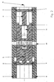
- control disks 2 and 3 are also coaxial to the axis of rotation 50, circular arc-shaped depressions, wherein it can be seen in Figure 4 that the circular arc-shaped depression in the control disc 3 consists of several sections, namely a central section 33, which has a greater width than the adjoining outer sections 34.
- ramps 35 are formed at the ends, which end on the essentially continuous upper surface of the control disk 3.
- the continuations of the sections 34 forming section 33 lie somewhat further away from the axis of rotation 50 with their radially inner wall, and the sections 34 end at ramps 36 which lead to the essentially continuous, flat surface of the control disk 3.
- a correspondingly shaped recess 37 is formed in the surface of the control disk 2 facing the pump carrier 1 (FIG. 3), but this recess is circumferentially opposite the recess formed by the sections 33 and 34 offset, as will be explained later in connection with the diagram of Figure 6.
- Rectangular plate elements 38, 39 serving as actuating devices for the valve arrangements are held non-rotatably on both sides of the pump support 1, the plate element 38 between the pump support 1 and the surface of the control disk 2 facing it and the plate element 39 between the pump support 1 and the surface facing it Control disc 3 is arranged and both plate elements 38, 39 lie with their longitudinal extension parallel to the central axis of the main channels 12, 13 lying on a common straight line.
- the two plate elements 38 and 39 have the same structure and consist of elastically deformable material, for example plastic or metal.
- each plate element 38, 39 has actuating cams 42, 43 and 40, 41 (FIGS. 3 and 4), of which the actuating cams 43 and 41 are spaced from the axis of rotation 50 such that when the control disks 2, 3 rotate, they pass through the two sections of the depressions in the control disks, that is to say the actuating cams 41, through the sections 33 and 36 of the depression in the control disk 3, and emerge from and at the one end ramp (36 in FIG. 4) the other end ramp (36 in Figure 4) can enter this.
- the actuating cams 42 and 40 of the plate elements 38 and 39 have a somewhat smaller distance from the axis of rotation 50, so that they can only enter the central portion of the depression, ie in of the control disk 3, the control cam 40 only passes through the section 33 and exits at one of the ramps 35 and enters the section 33 of the depression at the other ramp 35.
- the distance from the axis of rotation 50 is selected so that it is exactly centered with respect to the transverse sections 18 and 19 of the main channels 12, 13 are. Therefore, the actuating projection 44 is arranged centrally to the annular bead 26, the actuating projection 45 centrally to the annular bead 29, the actuating projection 46 centrally to the annular bead 28 and the actuating projection 47 centrally to the annular bead 27 (FIG. 3).
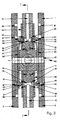
- sealing hoses 24 and 25 for example made of silicone rubber, on the sections of the cruciform pump support 1 forming the main channels 12, 13, which are firmly seated on these sections and which form the areas of the fluid channels 14 that form the lateral openings.
- Cover 16 and 15, 17 sealingly.
- the sealing hoses 24 and 25, which consist of easily elastically deformable material, are, as can be seen in particular in FIG. 3, by the elastic deformation of the ends of the plate elements 38 and 39 as a result of engagement with the actuating projections 46, 47 and 44, 45 located at these ends deformed so elastically that they come to the sealing contact on the adjacent annular bead and thereby seal the associated fluid channel from the main channel.
- the adjacent area of the sealing tube 24 is pressed against the annular bead 28, so that the annular channel 22 surrounding the annular bead 28, including the suction fluid channel 15 connected to this annular channel, seals against it the transverse section 18 and thus sealed off from the main intake duct 13, ie the suction connection for the pump chamber 11 is closed while its discharge connection is opened via the unsealed discharge fluid channel 16.
- the actuating projection 44 presses the adjacent area of the sealing tube 24 against the annular bead 26 and thereby seals the annular channel 20 and the intake fluid channel 17 with respect to the main intake channel 13, i.e. the suction connection for the pump chamber 10 is also closed, while the discharge connection via the discharge fluid channel 14 is open.
- the control disks 2, 3 rotate about the axis of rotation 50, so that the driver curves 30 and 31 and the cam surfaces of the control disks 2 and 3 delimited by the depressions 37 and 33 and 36 correspond to the shape of the curves act on the cam pins 6, 7 and 8, 9 of the pump pistons 4 and 5 and on the actuating cams 42, 43 and 40, 41 in order to reciprocate the pump pistons 4, 5 in a controlled manner for drawing in and expelling fluid, preferably liquid as well as opening and closing the intake fluid channels and the exhaust fluid channels in a controlled manner.
- FIG. 6 A typical and preferred course of these actuations is shown in the diagram according to FIG. 6, the suction movement of the pistons being faster than the ejection movement and the opening and closing movements of the various fluid channels taking place in the rest positions of the associated pump pistons, so that precisely defined amounts of liquid in the corresponding pump chamber are sucked in and expelled from it.
- the movement of the pump pistons 4, 5 takes place in such a way that the discharge of liquid through one pump piston begins when the discharge of liquid through the other pump piston ends, so that liquid is continuously conveyed, because of the constant displacement speed of the pump pistons during the discharge with constant delivery rate.
- the diagram according to FIG. 6 illustrates the different movement sequences during a complete revolution of the control disks 2, 3.
- the pump piston 5 is in the position that is fully retracted into the pump chamber 11, while the pump piston 4 is just beginning to move into the pump chamber 10, i.e. it ejects liquid, as shown in FIG Figures 1, 2 and 3 is shown.
- the suction fluid channel 17, which is in communication with the pump chamber 10 receiving the pump piston 4 is closed because the actuating cam 40 of the plate element 39 is in engagement with the cam surface of the control disk 3 and thereby an elastic deformation displacing the actuating projection 44 takes place.
- the discharge fluid channel 14 is open, so that liquid can be pressed out of the pump chamber 10 through the discharge fluid channel 14 into the main discharge channel 12.
- the ejection fluid channel 16, which is connected to the pump chamber 11, is still open because of the ejection movement of the pump piston 5 that has just ended (upper part of the diagram according to FIG. 6), but is closed shortly thereafter.
- the intake fluid channel 15 is correspondingly still closed, since the pump piston 5 is in the retracted position and no suction process is to take place.
- the pump piston 5 Only at approximately 52.5 °, the pump piston 5 is moved radially outward in accordance with the shape of the driver curves 30 and 31 at a relatively high speed with respect to the axis of rotation 50 and sucks in liquid through the intake fluid duct 15. This suction process ends at approximately 127.5 ° and the suction fluid channel 15 begins to close at approximately 135 °, so that it is completely closed at approximately 150 °. During this entire time, the pump piston 4 conveys liquid through the discharge fluid channel 14.
- the discharge channel 16 of the pump chamber 11 begins to open without a displacement movement of the pump piston 5 which is moved completely radially outwards. This opening process ends at approximately 172.5 °.
- the pump piston 4 has ended its ejection movement, and the pump piston 5 starts its ejection movement at the same speed as the pump piston 4. Only shortly thereafter, at approximately 187.5 °, the ejection fluid channel 14 of the pump chamber 10, and this fluid channel is closed at approximately 202.5 °. Then the suction fluid channel 17 of the pump chamber 10 begins to open at approximately 210 °. This opening movement is ended at about 225 °. It is only at approximately 232.5 ° that the return movement of the pump piston 4 and thus the suction of liquid through the open suction fluid channel 17 take place.
- the pump piston 4 and the associated fluid channels now work in the same manner as the pump piston 5 previously Start of its suction movement at approximately 52.5 °, so that the pump piston 4 is again in the position according to 0 ° at 360 ° and the pump piston 5 is in the position according to 0 ° at 360 °.
- driver curves 30 and 31 and the cam surfaces of the control disks 2 and 3 delimited by the recesses 33, 34 and 37 serve to control these movement sequences, and it is clear that by changing the shapes of these driver curves and cam surfaces a changed course of the Movements of the pump pistons and the opening and closing of the fluid channels can be effected.
- the radial piston pump shown is extremely simple, because it consists essentially of only 6 parts, namely the pump cross 1, a unit of control discs 2 and 3 fixedly connected by the shaft 49, two pump pistons 4, 5 and two Plate elements 38 and 39.
- these parts can be manufactured in a simple manner as mass articles, for example made of plastic, and nevertheless a very precisely controlled, continuous delivery of small amounts of liquid with an essentially constant delivery rate is possible with the aid of the pump .
Landscapes
- Engineering & Computer Science (AREA)
- Mechanical Engineering (AREA)
- General Engineering & Computer Science (AREA)
- Reciprocating Pumps (AREA)
- Details Of Reciprocating Pumps (AREA)
- Compressors, Vaccum Pumps And Other Relevant Systems (AREA)
Claims (13)
- Pompe à pistons radiaux comportant un support de pompe (1), dans lequel sont formées deux chambres de pompe (10,11), qui sont situées sur une droite (51) et dans lesquelles sont situés des pistons (4,5) de la pompe, qui se déplacent en va-et-vient le long de la droite (51) et qui, lors d'une rotation relative d'un élément d'entraînement, sont déplacés par rapport au support (1) de la pompe, autour d'un axe de rotation (50) qui recoupe la droite (51) et est situé en position centrée entre les chambres (10,11) de la pompe, et dans lequel à chacune des chambres (10;11) de la pompe est raccordé, au niveau de l'extrémité de la chambre proche de l'axe de rotation (50), au moins un canal (14,17;15,16) de circulation d'un fluide, qui est fermé en fonction de la position relative de l'élément d'entraînement et du support de pompe (1 ), caractérisée en ce que chaque chambre (10;11) de la pompe est raccordée à un canal (17;15) d'aspiration du fluide et un canal (14;16) d'éjection du fluide, dans lesquels sont prévus des dispositifs à soupape respectifs (24,25), qui coopèrent avec des dispositifs d'actionnement (38,39) prévus sur la partie d'entraînement, que les pistons (4,5) de la pompe sont déplacés en va-et-vient, avec des effets dirigés en des sens opposés, grâce à un accouplement à un élément d'entraînement, de sorte que le fluide est aspiré dans une chambre (10;11) de la pompe, par l'intermédiaire du canal (17;15) d'aspiration du fluide de cette chambre, tandis que le fluide est éjecté hors de l'autre chambre (11;10) de la pompe, par l'intermédiaire du canal (16;14) d'éjection du fluide de cette chambre, et que les canaux (15,17) d'aspiration du fluide sont raccordés à un canal commun d'aspiration principal (13) et que les canaux (14,16) d'éjection du fluide sont raccordés à un canal commun d'éjection principal (12).
- Pompe à pistons radiaux selon la revendication 1, caractérisée en ce que l'élément d'entraînement comporte au moins un disque de commande, qui peut tourner autour de l'axe de rotation (50) et qui porte au moins une came d'entraînement (30;31) pour un piston (4,5) de la pompe et sur laquelle est prévu un dispositif d'actionnement (38;39) pour au moins les dispositifs de soupapes situés dans le canal (15;17) d'aspiration du fluide d'une chambre (11;10) de la pompe et dans le canal (14;16) d'éjection du fluide de l'autre chambre (10;11) de la pompe.
- Pompe à pistons radiaux selon la revendication 2, caractérisée en ce que l'élément d'entraînement comporte deux disques de commande (2,3) montés coaxialement, situés des deux côtés du support de pompe (1) et qui agissent tous les deux sur des dispositifs d'actionnement respectifs identiques (38;39).
- Pompe à pistons radiaux selon la revendication 3, caractérisée en ce que chacun des disques de commande (2;3) comporte une came d'entraînement (30;31) pour les pistons (4;5) de la pompe.
- Pompe à pistons radiaux selon l'une des revendications 2 à 4, caractérisée en ce que les dispositifs d'actionnement comportent chacun un élément d'actionnement déformable élastiquement (38;39), qui est maintenu avec blocage en rotation sur le support de pompe (1) et aux extrémités duquel sont prévues, sur le côté tourné vers le support de pompe (1), des parties saillantes d'actionnement (46,47; 44,45) destinées à agir sur le dispositif de soupape associé (24;25), tandis que le côté, tourné vers le support de pompe (1), de l'élément d'actionnement (38;39) peut être amené à engrener avec les surfaces de came formées sur le disque de commande (2;3).
- Pompe à pistons radiaux selon la revendication 5, caractérisé en ce que des organes saillants d'actionnement (42,43; 40,41) sont prévus sur le côté de l'élément d'actionnement (38;39), qui est situé à l'opposé du support de pompe (1), et que la surface de came provoque, sous l'effet de l'engagement d'un organe saillant d'actionnement (40,41; 42,43), une déformation élastique de l'élément d'actionnement (38;39) servant à amener en prise une partie saillante d'actionnement (44,45;46,47).
- Pompe à pistons radiaux selon la revendication 6, caractérisée en ce qu'un complément, réalisé en forme d'arc de cercle, de la surface de came est constitué par un renfoncement (33,34;37) servant à recevoir l'organe saillant d'actionnement (40,41,42,43) et aux extrémités duquel sont prévues des rampes (35;36) formant des zones de jonction avec la surface de came.
- Pompe à pistons radiaux selon l'une des revendications 2 à 7, caractérisée en ce que sur chaque piston (4;5) de la pompe il est prévu au moins un ergot d'actionnement (6,7;8,9) qui fait saillie latéralement et qui vient en prise avec la came associée d'entraînement (30;31) du disque de commande (2;3).
- Pompe à pistons radiaux selon l'une des revendications 1 à 7, caractérisée en ce que chaque canal (14,15,16,17) pour la circulation du fluide comporte une ouverture latérale et est entouré, dans cette zone, par un tuyau d'étanchéité flexible (24;25), et que pour la fermeture du dispositif de soupape, l'élément d'actionnement (38;39) repousse le tuyau d'étanchéité (24;25) à travers l'ouverture latérale de manière qu'il soit appliqué d'une manière étanche contre la paroi, qui est située en face de lui, du canal (14;15;16;17) de circulation du fluide.
- Pompe à pistons radiaux selon la revendication 8, caractérisée par le fait que la paroi, qui est située en vis-à-vis de l'ouverture, est formée par une zone annulaire (26;27;28;29), qui entoure une section (18; 19), qui est perpendiculaire à l'axe médian de l'ouverture, du canal (14;15;16;17) de circulation du fluide.
- Pompe à pistons radiaux selon la revendication 10, caractérisée en ce qu'aussi bien les ouvertures des deux canaux (15;17) d'aspiration du fluide que les ouvertures des deux canaux (14,16) d'éjection du fluide sont réciproquement coaxiaux et que les sections, qui sont perpendiculaires à l'axe médian des ouvertures, sont reliées entre elles, le canal principal associé (12;13) étant raccordé à ces liaisons (18;19).
- Pompe à pistons radiaux selon l'une des revendications 1 à 11, caractérisée en ce que le déplacement d'aspiration des pistons (4;5) de la pompe est plus rapide que le déplacement d'éjection et qu'un piston (4;5) de la pompe est à l'arrêt lorsque commence le déplacement d'éjection de l'autre piston (5;4) de la pompe.
- Pompe à pistons radiaux selon la revendication 12, caractérisée en ce que l'ouverture et la fermeture des dispositifs de soupapes d'une chambre (10;11) de la pompe s'effectuent pendant l'arrêt du piston (4;5) de la pompe, situé dans la chambre (10;11) de la pompe.
Priority Applications (1)
| Application Number | Priority Date | Filing Date | Title |
|---|---|---|---|
| AT91107270T ATE102294T1 (de) | 1990-05-21 | 1991-05-04 | Radialkolbenpumpe. |
Applications Claiming Priority (2)
| Application Number | Priority Date | Filing Date | Title |
|---|---|---|---|
| DE4016306 | 1990-05-21 | ||
| DE4016306A DE4016306A1 (de) | 1990-05-21 | 1990-05-21 | Radialkolbenpumpe |
Publications (2)
| Publication Number | Publication Date |
|---|---|
| EP0458114A1 EP0458114A1 (fr) | 1991-11-27 |
| EP0458114B1 true EP0458114B1 (fr) | 1994-03-02 |
Family
ID=6406871
Family Applications (1)
| Application Number | Title | Priority Date | Filing Date |
|---|---|---|---|
| EP91107270A Expired - Lifetime EP0458114B1 (fr) | 1990-05-21 | 1991-05-04 | Pompe à pistons radiaux |
Country Status (5)
| Country | Link |
|---|---|
| US (1) | US5163822A (fr) |
| EP (1) | EP0458114B1 (fr) |
| AT (1) | ATE102294T1 (fr) |
| DE (2) | DE4016306A1 (fr) |
| ES (1) | ES2049500T3 (fr) |
Cited By (1)
| Publication number | Priority date | Publication date | Assignee | Title |
|---|---|---|---|---|
| DE102009057792A1 (de) | 2009-12-11 | 2011-06-16 | Kölln, Harm | Kontinuierlich fördernde Infusionspumpe |
Families Citing this family (5)
| Publication number | Priority date | Publication date | Assignee | Title |
|---|---|---|---|---|
| US6224346B1 (en) * | 1999-08-09 | 2001-05-01 | Medimop Medical Projects, Ltd. | Fluid pump |
| US6752064B2 (en) * | 2002-07-10 | 2004-06-22 | Roland T. Wheeler | Fluid pressure powered motor |
| US8418647B2 (en) * | 2005-10-21 | 2013-04-16 | Dürr Systems Inc. | Procedure and piston type metering devices for the metered material supply for a coating device |
| DE102006006555B4 (de) * | 2006-02-13 | 2008-03-06 | Siemens Ag | Hochdruckpumpe |
| US7951112B2 (en) * | 2007-05-16 | 2011-05-31 | Smiths Medical Asd, Inc. | Pump module for use in a medical fluid dispensing system |
Family Cites Families (10)
| Publication number | Priority date | Publication date | Assignee | Title |
|---|---|---|---|---|
| DE380040C (de) * | 1923-09-03 | Hermann Michel | Maschine mit durch Kurvenbahnen gesteuerten Arbeitskolben radialer Zylinder | |
| GB272955A (en) * | 1926-06-17 | 1928-06-28 | Livio Canale | Improvements in fluid-pressure engines and pumps |
| FR729061A (fr) * | 1931-01-02 | 1932-07-18 | Pompe pour masses composées de bouillie et de morceaux, béton par exemple | |
| DE2436627C2 (de) * | 1974-07-30 | 1984-04-26 | Alfred Teves Gmbh, 6000 Frankfurt | Ringförmiges Federelement zur Kopplung der Kolben einer Radialkolbenpumpe |
| US4167941A (en) * | 1976-10-05 | 1979-09-18 | James D. Pauls, Ltd. (Limited Partnership) | Mechanically operated dispensing device for increasing discharge pressure and dispensing time |
| US4173437A (en) * | 1977-08-01 | 1979-11-06 | The Perkin-Elmer Corporation | Dual-piston reciprocating pump assembly |
| US4359312A (en) * | 1978-08-15 | 1982-11-16 | Zumtobel Kg | Reciprocating pump for the pulsation-free delivery of a liquid |
| JPS5985665A (ja) * | 1982-09-13 | 1984-05-17 | イメツド・コ−ポレ−シヨン | 患者への流体供給装置および方法 |
| DE3615885A1 (de) * | 1986-05-09 | 1987-11-19 | Wolfgang Hoppe | Umlaufkolben-verdichter |
| US5066199A (en) * | 1989-10-23 | 1991-11-19 | Nalco Chemical Company | Method for injecting treatment chemicals using a constant flow positive displacement pumping apparatus |
-
1990
- 1990-05-21 DE DE4016306A patent/DE4016306A1/de not_active Ceased
-
1991
- 1991-05-04 AT AT91107270T patent/ATE102294T1/de not_active IP Right Cessation
- 1991-05-04 EP EP91107270A patent/EP0458114B1/fr not_active Expired - Lifetime
- 1991-05-04 DE DE91107270T patent/DE59101062D1/de not_active Expired - Fee Related
- 1991-05-04 ES ES91107270T patent/ES2049500T3/es not_active Expired - Lifetime
- 1991-05-21 US US07/702,811 patent/US5163822A/en not_active Expired - Lifetime
Cited By (2)
| Publication number | Priority date | Publication date | Assignee | Title |
|---|---|---|---|---|
| DE102009057792A1 (de) | 2009-12-11 | 2011-06-16 | Kölln, Harm | Kontinuierlich fördernde Infusionspumpe |
| WO2011069494A2 (fr) | 2009-12-11 | 2011-06-16 | Harm Kolln | Pompe à perfusion à transport continu |
Also Published As
| Publication number | Publication date |
|---|---|
| EP0458114A1 (fr) | 1991-11-27 |
| DE59101062D1 (de) | 1994-04-07 |
| US5163822A (en) | 1992-11-17 |
| DE4016306A1 (de) | 1991-11-28 |
| ES2049500T3 (es) | 1994-04-16 |
| ATE102294T1 (de) | 1994-03-15 |
Similar Documents
| Publication | Publication Date | Title |
|---|---|---|
| EP0492363B1 (fr) | Valve d'aspiration et/ou de refoulement pour une pompe de dosage ou de pulvérisation de produits liquides, à basse viscosité et pâteux | |
| EP1108439B1 (fr) | Distributeur de produit | |
| EP3116659B1 (fr) | Tête de distribution pour distributeur, distributeur équipé d'une tête de distribution et procédé de fabrication d'une tête de distribution | |
| DE3211778C2 (de) | Gaskältemaschine nach Gifford-McMahon | |
| WO2017211851A2 (fr) | Appareil de dosage et dispositif d'injection | |
| DE3921635A1 (de) | Hydro-radialkolbenpumpe | |
| EP4086490A1 (fr) | Soupape directionnelle de véhicule à moteur permettant de régler un écoulement de fluide | |
| EP0458114B1 (fr) | Pompe à pistons radiaux | |
| DE4311432C2 (de) | Taumelscheibenkompressor mit variabler Förderleistung | |
| DE69412910T2 (de) | Radialkolbenpumpe | |
| DE4411437C2 (de) | Axialkolbenkompressor mit Drehventil | |
| DE102017122488A1 (de) | Applikator mit einer Dichtungsmembran | |
| DE3019656A1 (de) | Hydromotor mit oszillierender welle | |
| DE19606703A1 (de) | Austragvorrichtung für Medien | |
| DE2634318A1 (de) | Pumpe, vorzugsweise zum dosieren und kalibrieren | |
| DE3119807C2 (de) | Rotationskolbenmaschine | |
| EP0356679A1 (fr) | Seringue d'injection à usage unique | |
| DE3542926C2 (fr) | ||
| DE4233990C2 (de) | Hochdruckreinigungsgerät | |
| DE3828274A1 (de) | Hydraulikpumpe | |
| DE69201966T2 (de) | Aufbau einer Peristaltikpumpe. | |
| DE4322560A1 (de) | Radialkolbenpumpe | |
| DE3928375C2 (de) | Kolbenpumpe | |
| DE69725458T2 (de) | Ventillose Dosierpumpe | |
| DE19953168A1 (de) | Drehkolbenmaschine |
Legal Events
| Date | Code | Title | Description |
|---|---|---|---|
| PUAI | Public reference made under article 153(3) epc to a published international application that has entered the european phase |
Free format text: ORIGINAL CODE: 0009012 |
|
| AK | Designated contracting states |
Kind code of ref document: A1 Designated state(s): AT BE CH DE DK ES FR GB GR IT LI LU NL SE |
|
| 17P | Request for examination filed |
Effective date: 19920228 |
|
| 17Q | First examination report despatched |
Effective date: 19920729 |
|
| GRAA | (expected) grant |
Free format text: ORIGINAL CODE: 0009210 |
|
| AK | Designated contracting states |
Kind code of ref document: B1 Designated state(s): AT BE CH DE DK ES FR GB GR IT LI LU NL SE |
|
| PG25 | Lapsed in a contracting state [announced via postgrant information from national office to epo] |
Ref country code: GR Free format text: LAPSE BECAUSE OF FAILURE TO SUBMIT A TRANSLATION OF THE DESCRIPTION OR TO PAY THE FEE WITHIN THE PRESCRIBED TIME-LIMIT Effective date: 19940302 Ref country code: DK Effective date: 19940302 Ref country code: NL Effective date: 19940302 Ref country code: BE Effective date: 19940302 |
|
| REF | Corresponds to: |
Ref document number: 102294 Country of ref document: AT Date of ref document: 19940315 Kind code of ref document: T |
|
| ITF | It: translation for a ep patent filed | ||
| REF | Corresponds to: |
Ref document number: 59101062 Country of ref document: DE Date of ref document: 19940407 |
|
| REG | Reference to a national code |
Ref country code: ES Ref legal event code: FG2A Ref document number: 2049500 Country of ref document: ES Kind code of ref document: T3 |
|
| GBT | Gb: translation of ep patent filed (gb section 77(6)(a)/1977) |
Effective date: 19940323 |
|
| ET | Fr: translation filed | ||
| PG25 | Lapsed in a contracting state [announced via postgrant information from national office to epo] |
Ref country code: LU Free format text: LAPSE BECAUSE OF NON-PAYMENT OF DUE FEES Effective date: 19940531 |
|
| NLV1 | Nl: lapsed or annulled due to failure to fulfill the requirements of art. 29p and 29m of the patents act | ||
| PLBE | No opposition filed within time limit |
Free format text: ORIGINAL CODE: 0009261 |
|
| STAA | Information on the status of an ep patent application or granted ep patent |
Free format text: STATUS: NO OPPOSITION FILED WITHIN TIME LIMIT |
|
| EAL | Se: european patent in force in sweden |
Ref document number: 91107270.0 |
|
| 26N | No opposition filed | ||
| REG | Reference to a national code |
Ref country code: CH Ref legal event code: PUE Owner name: KITRONIC GESELLSCHAFT FUER MIKROTECHNIK IN DER MED |
|
| REG | Reference to a national code |
Ref country code: FR Ref legal event code: TP |
|
| REG | Reference to a national code |
Ref country code: ES Ref legal event code: PC2A |
|
| REG | Reference to a national code |
Ref country code: GB Ref legal event code: 732E |
|
| PGFP | Annual fee paid to national office [announced via postgrant information from national office to epo] |
Ref country code: ES Payment date: 20010427 Year of fee payment: 11 |
|
| PGFP | Annual fee paid to national office [announced via postgrant information from national office to epo] |
Ref country code: CH Payment date: 20010510 Year of fee payment: 11 |
|
| PGFP | Annual fee paid to national office [announced via postgrant information from national office to epo] |
Ref country code: AT Payment date: 20010514 Year of fee payment: 11 |
|
| REG | Reference to a national code |
Ref country code: GB Ref legal event code: IF02 |
|
| PG25 | Lapsed in a contracting state [announced via postgrant information from national office to epo] |
Ref country code: AT Free format text: LAPSE BECAUSE OF NON-PAYMENT OF DUE FEES Effective date: 20020504 |
|
| PG25 | Lapsed in a contracting state [announced via postgrant information from national office to epo] |
Ref country code: ES Free format text: LAPSE BECAUSE OF NON-PAYMENT OF DUE FEES Effective date: 20020505 |
|
| PG25 | Lapsed in a contracting state [announced via postgrant information from national office to epo] |
Ref country code: LI Free format text: LAPSE BECAUSE OF NON-PAYMENT OF DUE FEES Effective date: 20020531 Ref country code: CH Free format text: LAPSE BECAUSE OF NON-PAYMENT OF DUE FEES Effective date: 20020531 |
|
| REG | Reference to a national code |
Ref country code: CH Ref legal event code: PL |
|
| REG | Reference to a national code |
Ref country code: ES Ref legal event code: FD2A Effective date: 20030611 |
|
| PG25 | Lapsed in a contracting state [announced via postgrant information from national office to epo] |
Ref country code: IT Free format text: LAPSE BECAUSE OF NON-PAYMENT OF DUE FEES;WARNING: LAPSES OF ITALIAN PATENTS WITH EFFECTIVE DATE BEFORE 2007 MAY HAVE OCCURRED AT ANY TIME BEFORE 2007. THE CORRECT EFFECTIVE DATE MAY BE DIFFERENT FROM THE ONE RECORDED. Effective date: 20050504 |
|
| PGFP | Annual fee paid to national office [announced via postgrant information from national office to epo] |
Ref country code: DE Payment date: 20070426 Year of fee payment: 17 |
|
| PGFP | Annual fee paid to national office [announced via postgrant information from national office to epo] |
Ref country code: SE Payment date: 20070508 Year of fee payment: 17 |
|
| PGFP | Annual fee paid to national office [announced via postgrant information from national office to epo] |
Ref country code: GB Payment date: 20070502 Year of fee payment: 17 |
|
| PGFP | Annual fee paid to national office [announced via postgrant information from national office to epo] |
Ref country code: FR Payment date: 20070510 Year of fee payment: 17 |
|
| GBPC | Gb: european patent ceased through non-payment of renewal fee |
Effective date: 20080504 |
|
| REG | Reference to a national code |
Ref country code: FR Ref legal event code: ST Effective date: 20090119 |
|
| PG25 | Lapsed in a contracting state [announced via postgrant information from national office to epo] |
Ref country code: FR Free format text: LAPSE BECAUSE OF NON-PAYMENT OF DUE FEES Effective date: 20080602 Ref country code: DE Free format text: LAPSE BECAUSE OF NON-PAYMENT OF DUE FEES Effective date: 20081202 |
|
| PG25 | Lapsed in a contracting state [announced via postgrant information from national office to epo] |
Ref country code: GB Free format text: LAPSE BECAUSE OF NON-PAYMENT OF DUE FEES Effective date: 20080504 |
|
| PG25 | Lapsed in a contracting state [announced via postgrant information from national office to epo] |
Ref country code: SE Free format text: LAPSE BECAUSE OF NON-PAYMENT OF DUE FEES Effective date: 20080505 |