EP0457325A2 - Unité de reconnaissance et dispositif de reconnaissance et de jugement utilisant de telles unités - Google Patents
Unité de reconnaissance et dispositif de reconnaissance et de jugement utilisant de telles unités Download PDFInfo
- Publication number
- EP0457325A2 EP0457325A2 EP91107961A EP91107961A EP0457325A2 EP 0457325 A2 EP0457325 A2 EP 0457325A2 EP 91107961 A EP91107961 A EP 91107961A EP 91107961 A EP91107961 A EP 91107961A EP 0457325 A2 EP0457325 A2 EP 0457325A2
- Authority
- EP
- European Patent Office
- Prior art keywords
- path
- section
- recognition unit
- output
- signal
- Prior art date
- Legal status (The legal status is an assumption and is not a legal conclusion. Google has not performed a legal analysis and makes no representation as to the accuracy of the status listed.)
- Granted
Links
Images


Classifications
-
- G—PHYSICS
- G06—COMPUTING; CALCULATING OR COUNTING
- G06N—COMPUTING ARRANGEMENTS BASED ON SPECIFIC COMPUTATIONAL MODELS
- G06N3/00—Computing arrangements based on biological models
- G06N3/02—Neural networks
- G06N3/04—Architecture, e.g. interconnection topology
Definitions
- the present invention relates to a recognition unit and a recognizing and judging apparatus employing a plurality of recognition units for recognizing and judging an object according to various characteristic data of the object.
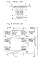
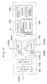
- Fig. 1 is a block diagram indicating a conventional recognizing and judging apparatus, which comprises a template comparator 1 having a signal input terminal 2 and a signal output terminal 3, a plurality of templates 4-7 of input signal patterns prepared in advance, and a learning device 8 having a teacher signal input terminal 9.
- a series of signals representative of an object to be recognized are inputted from the signal input terminal 2 to the template comparator 1.
- the template comparator 1 compares a pattern of the inputted signals with each of the templates 4-7 and outputs the number of a template having the smallest error as a recognition result from the signal output terminal 3. If the output result is incorrect, the number of a template to which the inputted signals should belong is inputted from the teacher signal input terminal 9 to the learning device 8, thereby modifying an appropriate template to improve the recognizing percentage.
- a learning type recognizing and judging apparatus is known, for example, in "Learning Representations by Back-Propagating Errors" written by D. E. Rumelhart et al. and reported in Vol. 323, No. 9(1986) of "Nature".
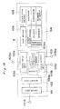
- Fig. 2 is a block diagram indicating the structure of one of conventional learning type recognizing and judging apparatus, which comprises a plurality of input terminals 11 and 12, a plurality of output terminals 22, a learning circuit 27, a plurality of multi-input/output circuits 28-30, an output layer 31, and a hidden layer 32.
- the plurality of multi-input/output circuits 28-30 are organized in a hierarchical manner in the learning type recognizing and judging apparatus, in which signals inputted from the input terminals 11 and 12 are processed and outputted from the output terminals 22.
- the hidden layer may consist of either a single layer or a plurality of layers each including multi-input/output circuits.
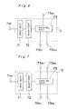
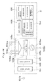
- Fig. 3 is a block diagram indicating the structure of another conventional learning type recognizing and judging apparatus, which comprises input terminals 41 and 42, a plurality of variable weight multipliers 43-48, a plurality of adders 49-51 each having a saturation input/output characteristic, an output terminal 52, a teacher signal generating section 53, an error calculating section 54, a steepest-descent-direction deciding section 55, a weight changing section 56, a learning circuit 57, a plurality of multi-input/output circuits 58-60, an output layer 61, and a hidden layer 62.
- each of the multi-input/output circuits 58-60 includes two variable weight multipliers and one adder having the saturation input/output characteristic.
- an output signal of the j-th multi-input/output circuit is expressed as: where y[i] is an output signal of the i-th multi-input/output circuit of the preceding layer; w[i, j] is a weight to be applied when the output signal of the i-th multi-input/output circuit of the preceding layer is inputted to the j-th multi-input/output circuit; and fnc( ) is a function having a saturation characteristic and is expressed by, for example, the following Sigmoid function:
- Fig. 4 is a graph representative of the characteristic function of the adders 49-51 each having a saturation input/output characteristic expressed by the above fnc( ).
- the learning type recognizing and judging apparatus has a structure in which multi-input/output circuits are hierarchically connected with each other.
- weights applied to the variable multipliers 43-48 are changed so that a desirable output signal (hereinafter referred to as a teacher signal) may be outputted in response to input signals.
- a teacher signal a desirable output signal
- an error is found from the teacher signal and the output signal of the output layer in order to determine the amount of changes of the weights.
- y p [j] is an output signal of the j-th multi-input/output circuit of the output layer in response to the p-th input signal
- t p [j] is a teacher signal with respect to y p [j]
- the error E is expressed by the sum of squares of the differences between the teacher signals and the corresponding output signals of the output layer and is a function of the weight vector .
- ⁇ is a positive constant called the "learning parameter”
- ⁇ is a positive constant called the "momentum”
- ⁇ ' is a vector expression of the amount of changes of the weights in the previous learning.
- Fig. 5 schematically depicts the structure of the learning circuit 57 of the conventional learning type recognizing and judging apparatus.
- the learning circuit 57 has an input terminal 63 for receiving output signals from the output layer, an input terminal 64 for receiving output signals from the hidden layer, an input terminal 65 for receiving input signals, an output terminal 66 for outputting weights to the output layer, and an output terminal 67 for outputting weights to the hidden layer.
- the teacher signal generating section 53 generates a teacher signal t p [j] (desirable output signal) in response to an input signal.
- the error calculating section 54 calculates the error E expressed by Equation (2) based on the teacher signal t p [j] and the output signal y p [j] of the output layer.
- the error calculating section 54 outputs a difference signal t p [j] - y p [j] between the teacher signal required for changing the weights and the output signal to the steepest-descent-direction deciding section 55.
- the steepest-descent-direction deciding section 55 finds the steepest descent direction of the error E in a space of weights, in which the weights are expressed in vector, based on output signals of the output layer, output signals of the hidden layer, input signals, and weights of the output layer.
- the steepest descent direction is found by:
- Equation (4) is a vector expression of the partial derivative of the error E with respect to the weight.
- the steepest-descent-direction deciding section 55 multiplies the steepest descent direction by the learning parameter and outputs the result to the weight changing section 56.
- the weight changing section 56 finds the amount of changes of the weights using Equation (3), thereby changing the weight to be multiplied in each of the variable weight multipliers 43-48. As described above, iteratively finding the amount of changes of the weights by the use of the steepest descent method can reduce the error. When the error becomes considerably small, the learning is terminated by reason that the output signal has reached a satisfactorily desirable value.
- the structure of a network cannot be altered from a fixed state initially defined or designed. Accordingly, since the learning and the recognition ability are determined by the initial design, the apparatus cannot provide an appropriate processing according to input data. Furthermore, any method of designing the network has not been established and actual designing fully depends upon trial and error based on experience and perception.
- the present invention has been developed to overcome the above-described disadvantages.
- Another object of the present invention is to provide a recognizing and judging apparatus of the above-described type which enables not only learning to be made in response to input data, but also the structure of a network to be automatically appropriately altered, constructed, and self-organized in response to input signals.
- a recognition unit comprises a signal input section, a quantizer for performing a quantization according to a signal inputted from the signal input section, and a path selecting section having at least one path input terminal and at least one path output terminal.
- the path selecting section performs a selection of paths according to an output of the quantizer.
- a recognizing and judging apparatus includes a plurality of recognition units organized in the form of a multi-layered hierarchical network.
- various characteristic data of an object to be recognized are initially inputted to the signal input sections of the recognition units in some upper layers. Connecting paths between the recognition units are then switched according to outputs of the quantizers of the recognition units, and a desired path leading to the lowermost layer is selectively determined so that a recognition result may be obtained. Therefore, recognition processing and learning of the object can be performed at a high speed.
- a recognition unit comprises a basic unit having at least a signal input section, a function-processing section and a signal output section, a structure storage means for storing a structure of the basic unit, an internal state storage means for storing an internal state of the basic unit, and a duplicating means for duplicating the basic unit based on the internal state of the basic unit stored in the internal state storage means.
- the internal state stored in the internal state storing means changes according to input data.
- the duplicate means duplicates some recognition units at respective appropriate locations based on the structure of a network stored in the internal state storing means.
- the network is reconstituted in the apparatus so as to automatically adapt itself to the input data.
- the basic unit may be comprised of a signal input section, a quantizer for performing a quantization according to a signal inputted from the signal input section, and a path selecting section having at least one path input terminal and at least one path output terminal.
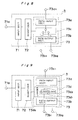
- the recognition unit comprises a signal input section 71 to which characteristic data to be recognized are inputted via a signal input terminal 71a, a quantizer 72 for quantizing the inputted characteristic data, and a path selecting section 73 for changing the connection between a path input terminal 73a1 and path output terminals 73b1 and 73b2 based upon a value quantized by and inputted from the quantizer 72.
- a network is constituted by the combination of a plurality of recognition units, respective terminals 73a1, 73b1 and 73b2 of the recognition units are connected with one another.
- Fig. 7 schematically shows a recognition unit according to a second embodiment of the present invention, in which a plurality of path input terminals (in this case, two terminals 73a1 and 73a2) are provided.
- This recognition unit can be operated similarly to that shown in Fig. 6.
- Fig. 8 schematically shows a recognition unit according to a third embodiment of the present invention.
- the path selecting section 73 comprises a path input section 73a having one path input terminal 73a1, a path output section 73b having two path output terminals 73b1 and 73b2, and a switch 73c.
- the switch 73c switches the connection between the path input terminal 73a1 of the path input section 73a and the path output terminals 73b1 and 73b2 of the path output section 73b based on a value inputted thereto from the quantizer 2.
- Fig. 9 schematically shows a recognition unit according to a fourth embodiment of the present invention.
- the path selecting section 73 comprises a path input section 73a having one path input terminal 73a1, a path output section 73b having two path output terminals 73b1 and 73b2, and a path loading section 73d.
- Loads 73d1 and 73d2 are weights to be applied to path output signals to be outputted to the path output terminals 73b1 and 73b2 of the path output section 73b, respectively.
- a loader 73d0 changes these loads according to a value outputted from the quantizer 72.
- the loads 73d1 and 73d2 weight a path signal inputted from the path input section whereas the path output section 73b outputs the weighted path signal to the path output terminals 73b1 and 73b2.
- Fig. 10 schematically shows a recognition unit according to a fifth embodiment of the present invention.
- the path input section 73a comprises an adder 73a0 for adding input signals from a plurality of path input terminals to one another whereas the path output section 73b comprises a threshold processor 73b0 for performing threshold processing with respect to path signals.
- the adder 73a0 adds path signals inputted from eight path input terminals 73a1-73a8 and inputs the result of addition to a path selector 73e.
- the path selector 73e decides how to output a signal obtained through the addition to the path output terminal according to a value outputted from the quantizer 72.
- the path selector 73e may be of either the construction as shown in Fig.
- the path selector 73e decides whether or not the path signal is outputted in the case where the construction as shown in Fig. 8 is employed or the path selector 73e changes the load for weighting the path signal in the case where the construction as shown in Fig. 9 is employed.
- Fig. 11 schematically shows a recognition unit according to a sixth embodiment of the present invention.
- the recognition unit comprises a signal input section 81 to which various data signals are inputted through signal input terminals 91-94, and a function-processing section 82 for processing inputted data using a function, for example a threshold function such as Sigmoid function, and a signal output section 83 for outputting processed data via an output terminal 83a thereof.
- a function for example a threshold function such as Sigmoid function
- a signal output section 83 for outputting processed data via an output terminal 83a thereof.
- the recognition unit according to this embodiment further comprises a structure storage means 84, an internal state storage means 85, and a duplicating means 86.
- the structure storage means 84 stores various informations such as the structure of the signal input section 81, the number of output terminals of the signal output section 83, and the contents processed by the function-processing section 82.
- the internal state storage means 85 stores the internal state of the recognition unit which changes momentarily in response to inputted signals.
- the duplicating means 86 duplicates the recognition unit according to the structure of the recognition unit stored in the structure storage means 84 when the internal state stored in the internal state storage means 85 reaches a certain value.
- Fig. 12 schematically shows a recognition unit according to a seventh embodiment of the present invention.
- the recognition unit comprises a signal input section 101 to which characteristic data to be recognized are inputted via a signal input terminal 101a, a quantizer 102 for quantizing the inputted characteristic data, and a path selecting section 103 for changing the connection between a path input terminal 103a and path output terminals 103b1 and 103b2 based upon a value quantized by and inputted from the quantizer 102.
- a network is constituted by the combination of a plurality of recognition units, respective terminals 103a, 103b1 and 103b2 of the recognition units are connected with one another.
- the recognition unit further comprises a structure storage means 104, an internal state storage means 105, and a duplicating means 106.
- the structure storage means 104 stores the range to be quantized by the quantizer, the number of quantization, the number of the path input and output terminals of the path selecting section 103.
- the internal state storage means 105 stores the average, dispersion, and total number of inputted signals as the internal state of the recognition unit.
- the duplicating means 106 duplicates the recognition unit according to the structure of the recognition unit stored in the structure storage means 104 when the internal state stored in the internal state storage means 105 reaches a certain value.
- Fig. 13 schematically shows a recognition unit according to an eighth embodiment of the present invention, in which a plurality of path input terminals (in this case, two path input terminals, 103a1 and 103a2) are provided.
- This recognition unit can be operated similarly to that shown in Fig. 12.
- Fig. 14 schematically shows a recognition unit according to a ninth embodiment of the present invention.
- a path selecting section 103 is constructed by a path input section 103a having one path input terminal 103a1, a path output section 103b having two path output terminals 103b1 and 103b2, and a switch 103c.
- the switch 103c connects the path input terminal 103a1 of the path input section 103a and the path output terminal 103b1 or 103b2 of the path output section 103b with each other based on a value inputted thereto from the quantizer 102.
- a path selecting section 103 comprises a path input section 103a having one path input terminal 103a1 and a path output section 103b having two path output terminals 103b1 and 103b2, and a path loading section 103d.
- Loads 103d1 and 103d2 are weights to be applied to path output signals to be outputted to the path output terminals 103b1 and 103b2 of the path output section 103b, respectively.
- a loader 103d0 changes these loads according to a value outputted from the quantizer 102.
- the loads 103d1 and 103d2 weight a path signal inputted from the path input section whereas the path output section 103b outputs the weighted path signal to the path output terminals 103b1 and 103b2.
- a path input section 103a comprises an adder 103a0 for adding input signals from a plurality of path input terminals whereas a path output section 103b comprises a threshold processor 103b0 for performing threshold processing with respect to path signals.
- the adder 103a0 adds path signals inputted from eight path input terminals 103a1-103a8 and inputs the result of addition to a path selector 103e.
- the path selector 103e decides how to output a signal obtained through the addition to the path output terminal according to a value outputted from the quantizer 102.
- the path selector 103e may be of either the construction as shown in Fig.
- the path selector 103e decides whether or not the path signal is outputted in the case where the construction as shown in Fig. 14 is employed or the path selector 103e changes the load for weighting the path signal in the case where the construction as shown in Fig. 15 is employed.
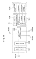
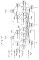
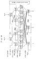
- Fig. 17 schematically shows a recognizing and judging apparatus, in which a network is constructed by connecting a plurality of recognition units according to the present invention in a multi-layered hierarchical structure.
- the recognition unit as shown in Fig. 8 is used as recognition units n11 - n12 , n21 - n24 , and n31 - n38 constituting a first, a second, and a third layer, respectively.
- a path selecting section 73 comprises a path input section 73a having one path input terminal 73a1, a path output section 73b having two path output terminals 73b1 and 73b2, and a switch 73c.
- a path input section 73a comprises an adder 73a0 for adding input signals from the plurality of path input terminals whereas a path output section 73b comprises a threshold processor 73b0 for performing threshold processing with respect to path signals.
- the recognizing and judging apparatus as shown in Fig. 17 classifies objects to be recognized into three categories based upon three kinds of each two characteristic data.
- the learning operation of the recognizing and judging apparatus shown in Fig. 17 is as follows.
- “1" is initially given as a path signal to the path input terminal of each of the recognition units n11 and n12 of the first layer.
- a series of first characteristic data of an object to be recognized are inputted to the signal input terminal of the quantizer of each of these units. (In this figure, two first characteristic data are inputted to two recognition units, respectively.)
- These first characteristic data are quantized by the quantizers of the recognition units n11 and n12 .
- Paths p11 and p12 are then selected by the switch shown in Fig. 8 based on respective values quantized, and a path signal "1" is sent to the path input terminal of each of the recognition units n22 and n23 of the second layer.
- a series of second characteristic data of the object are inputted to the signal input terminal of each quantizer of these units.
- two second characteristic data are inputted to two recognition units n22 and n23, respectively.
- These second characteristic data are quantized by the quantizers of the recognition units n22 and n23 .
- Paths p21 and p22 are then selected by the switch shown in Fig. 8 based upon respective values quantized, and a path signal "1" is sent to the path input terminal of each of the recognition units n34 and n36 of the third layer.
- a teacher signal indicating which of three categories to be classified the object belongs to namely, a signal indicating which of n41-n43 should be selected is inputted to the signal input terminal of the quantizer of each of these units.
- the teacher signal is inputted to two recognition units n34 and n36 .
- the teacher signal is quantized by the quantizers of the recognition units n34 and n36, and paths p31 and p32 are selected by the switch shown in Fig. 8 based on values quantized.
- the learning process of the recognizing and judging apparatus As described above, in the learning process of the recognizing and judging apparatus according to the present invention, various characteristic data of each object to be recognized are inputted to the signal input section of each recognition unit constituting a multi-layered hierarchical network. Connection paths between recognition units are switched according to outputs of the quantizers. In a layer adjacent to the lowermost layer, the teacher signal merely determines the selection of path towards the lowermost layer. Accordingly, the learning processing can be performed at a very high speed. Furthermore, the apparatus according to the present invention is superior in additional learning because, fundamentally, only the addition or alteration of connection paths of recognition units is required to perform the additional learning.
- the recognition operation by the apparatus according to the present invention is as follows.
- the recognition units n11 , n12 , n22 , and n23 similarly to the learning operation, respective quantizers quantize inputted characteristic data, and connection paths are switched based on values quantized, thereby sequentially selecting the paths p11, p12, p21, and p22.
- no teacher signal is inputted to the signal input terminal of each of the recognition units n34 and n36 . Accordingly, the state of the switches during the learning is kept, and the paths p31 and p32 are selected according to the state of these switches, and a path signal "1" is sent to the path input terminal of the recognition unit n42 of the fourth layer.
- the adder of the path input section of this unit adds path signals inputted through the paths p31 and p32 to each other.
- the signal "1" is inputted to the signal input terminal of the signal input section, and the quantizer quantizes this signal so that the path selector may enable the path output. (When a signal "0" is inputted, the path selector switches so that the path output may be disabled.)
- a path signal obtained through the addition is sent to the path output section, which performs threshold processing with respect thereto and outputs the processing result to the path output terminal. Accordingly, when the signal after the addition is greater than a certain threshold value, the signal is outputted through the path output terminal. In this way, objects to be recognized can be classified into respective appropriate categories for recognition and judgement thereof based on inputted characteristic data thereof. Sigmoid function, Step function or the like can be used as a function for performing the threshold processing.
- recognizing process of the recognizing and judging apparatus various characteristic data of each object to be recognized are inputted to the signal input section of each recognition unit constituting a multi-layered hierarchical network. Connection paths between recognition units are switched according to outputs of respective quantizers. In a layer adjacent to the lowermost layer, a recognition result is obtained only by determining the selection path to the lowermost layer based on a connection path set in the learning process. Therefore, recognition processing can be performed at a very high speed based on the learning result.
- a signal taking a value from 1 to 10 is initially inputted to the signal input terminal 101a of the signal input section 101 of the recognition unit, which originates the duplicate.
- the range of quantization by the quantizer 102 is set to 1 to 10.
- the internal state storage means 105 calculates and stores the average, dispersion, and the number of inputs of sequentially inputted data signals whenever a data signal is inputted.
- the duplicating means duplicates information of this recognition unit to an unused vacant recognition unit with reference to the range of quantization of the quantizer, the number of quantization, and the number of path input and output terminals of the path selecting section stored in the structure storage means.
- the duplicating means produces a duplicate identical to itself including the connection with other recognition units.
- the duplicate is produced so that the original unit and the duplicate shares functions by dividing a necessary range of quantization into 1 to 10, for example, by setting the range of quantization of the quantizer of the original recognition unit to 1 to 5 and the range of quantization of the quantizer of the duplicate to 6 to 10.
- Fig. 18 schematically shows a learning type recognizing and judging apparatus according to the present invention.
- a network is constructed by connecting a plurality of recognition units with one another in a multi-layered hierarchical structure.
- the recognition unit as shown in Fig. 14 is used as recognition units n11 - n12 , n21 - n24 , and n31 - n38 constituting a first, a second, and a third layer, respectively.
- the path selecting section 103 comprises the path input section 103a having one path input terminal 103a1, the path output section 103b having two path output terminals 103b1 and 103b2, and the switch 103c.
- the path input section 103a comprises the adder 103a0 for adding input signals from the plurality of path input terminals whereas the path output section 103b comprises the threshold processor 103b0 for performing threshold processing with respect to path signals.
- the learning type recognizing and judging apparatus as shown in Fig. 18 classifies objects to be recognized into three categories based upon three kinds of each two characteristic data.
- the learning operation of the learning type recognizing and judging apparatus shown in Fig. 18 is substantially the same as that of the recognizing and judging apparatus shown in Fig. 17.
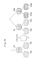
- duplicating recognition units in the learning type recognizing and judging apparatus shown in Fig. 18 is discussed hereinafter with reference to Fig. 19.
- a duplicate detecting section S detects all recognition units which have initiated a duplicate operation, thus issuing instructions so that all recognition units including those connected thereto in the lower thereof may be duplicated.
- a recognition unit 111 is duplicated together with recognition units 112 and 113 both connected thereto in the lower layer thereof, i.e., a duplicate recognition unit 111a and duplicate recognition units 112a and 113a connected thereto in the lower layer thereof are newly produced. Accordingly, not only the learning of a network is performed in response to input data, but also the structure of the network can be automatically altered, constructed, and self-organized according to input signals so that the network may adapt itself to the input signals.
- the internal state of each recognition unit changes according to input data, and the duplicate detecting means initiates the duplicating operation.
- the apparatus according to the present invention can readily adapt itself to new data which the apparatus has not learned.
- the learning type recognizing and judging apparatus shown in Fig. 8 can perform the learning processing at a very high speed.
Landscapes
- Engineering & Computer Science (AREA)
- Theoretical Computer Science (AREA)
- Physics & Mathematics (AREA)
- Data Mining & Analysis (AREA)
- General Health & Medical Sciences (AREA)
- Biomedical Technology (AREA)
- Biophysics (AREA)
- Computational Linguistics (AREA)
- Life Sciences & Earth Sciences (AREA)
- Evolutionary Computation (AREA)
- Artificial Intelligence (AREA)
- Molecular Biology (AREA)
- Computing Systems (AREA)
- General Engineering & Computer Science (AREA)
- General Physics & Mathematics (AREA)
- Mathematical Physics (AREA)
- Software Systems (AREA)
- Health & Medical Sciences (AREA)
- Image Analysis (AREA)
Applications Claiming Priority (4)
| Application Number | Priority Date | Filing Date | Title |
|---|---|---|---|
| JP127286/90 | 1990-05-16 | ||
| JP2127286A JP2767974B2 (ja) | 1990-05-16 | 1990-05-16 | 単位認識ユニット及び認識判断装置 |
| JP2266927A JP2762735B2 (ja) | 1990-10-03 | 1990-10-03 | 単位認識ユニット及び学習型認識判断装置 |
| JP266927/90 | 1990-10-03 |
Publications (3)
| Publication Number | Publication Date |
|---|---|
| EP0457325A2 true EP0457325A2 (fr) | 1991-11-21 |
| EP0457325A3 EP0457325A3 (en) | 1993-04-28 |
| EP0457325B1 EP0457325B1 (fr) | 1997-09-03 |
Family
ID=26463277
Family Applications (1)
| Application Number | Title | Priority Date | Filing Date |
|---|---|---|---|
| EP91107961A Expired - Lifetime EP0457325B1 (fr) | 1990-05-16 | 1991-05-16 | Unité de reconnaissance et dispositif de reconnaissance et de jugement utilisant de telles unités |
Country Status (3)
| Country | Link |
|---|---|
| US (2) | US5265224A (fr) |
| EP (1) | EP0457325B1 (fr) |
| DE (1) | DE69127495T2 (fr) |
Cited By (1)
| Publication number | Priority date | Publication date | Assignee | Title |
|---|---|---|---|---|
| EP0567983A2 (fr) * | 1992-04-30 | 1993-11-03 | Matsushita Electric Industrial Co., Ltd. | Dispositif d'apprentissage de reconnaissance de la forme d'onde |
Families Citing this family (15)
| Publication number | Priority date | Publication date | Assignee | Title |
|---|---|---|---|---|
| US5329594A (en) * | 1991-03-06 | 1994-07-12 | Matsushita Electric Industrial Co., Ltd. | Recognizing and judging apparatus |
| US5408588A (en) * | 1991-06-06 | 1995-04-18 | Ulug; Mehmet E. | Artificial neural network method and architecture |
| US5357597A (en) * | 1991-06-24 | 1994-10-18 | International Business Machines Corporation | Convolutional expert neural system (ConExNS) |
| DE69228337T2 (de) * | 1991-06-27 | 1999-06-17 | Matsushita Electric Ind Co Ltd | Erkennungs- und Beurteilungsgerät |
| JP3169635B2 (ja) * | 1991-07-03 | 2001-05-28 | 本田技研工業株式会社 | ニューラルネットワーク及びその学習方法 |
| US5479570A (en) * | 1992-10-06 | 1995-12-26 | Matsushita Electric Industrial Co., Ltd. | Learning and recognition machine |
| JP2737583B2 (ja) * | 1992-11-26 | 1998-04-08 | 松下電器産業株式会社 | ニューラルネットワーク回路 |
| GB9307611D0 (en) * | 1993-04-13 | 1993-06-02 | Univ Strathclyde | Object recognition |
| EP0683489B1 (fr) | 1994-05-18 | 2003-12-17 | Matsushita Electric Industrial Co., Ltd. | Appareil d'enregistrement et de reproduction à signal d'apprentissage |
| US6212668B1 (en) | 1996-05-28 | 2001-04-03 | Altera Corporation | Gain matrix for hierarchical circuit partitioning |
| US5832484A (en) * | 1996-07-02 | 1998-11-03 | Sybase, Inc. | Database system with methods for parallel lock management |
| US6301694B1 (en) | 1996-09-25 | 2001-10-09 | Altera Corporation | Hierarchical circuit partitioning using sliding windows |
| US6052679A (en) * | 1997-09-11 | 2000-04-18 | International Business Machines Corporation | Artificial neural networks including Boolean-complete compartments |
| US6054710A (en) * | 1997-12-18 | 2000-04-25 | Cypress Semiconductor Corp. | Method and apparatus for obtaining two- or three-dimensional information from scanning electron microscopy |
| US6526470B1 (en) * | 1998-09-28 | 2003-02-25 | Cypress Semiconductor Corp. | Fifo bus-sizing, bus-matching datapath architecture |
Family Cites Families (9)
| Publication number | Priority date | Publication date | Assignee | Title |
|---|---|---|---|---|
| JPH0634236B2 (ja) * | 1985-11-02 | 1994-05-02 | 日本放送協会 | 階層型情報処理方法 |
| US4805225A (en) * | 1986-11-06 | 1989-02-14 | The Research Foundation Of The State University Of New York | Pattern recognition method and apparatus |
| US4811404A (en) * | 1987-10-01 | 1989-03-07 | Motorola, Inc. | Noise suppression system |
| US5155802A (en) * | 1987-12-03 | 1992-10-13 | Trustees Of The Univ. Of Penna. | General purpose neural computer |
| JPH0738186B2 (ja) * | 1989-03-13 | 1995-04-26 | シャープ株式会社 | 自己拡張形ニユーラル・ネットワーク |
| US5151969A (en) * | 1989-03-29 | 1992-09-29 | Siemens Corporate Research Inc. | Self-repairing trellis networks |
| US5063521A (en) * | 1989-11-03 | 1991-11-05 | Motorola, Inc. | Neuram: neural network with ram |
| US5052043A (en) * | 1990-05-07 | 1991-09-24 | Eastman Kodak Company | Neural network with back propagation controlled through an output confidence measure |
| US5085526A (en) * | 1990-07-26 | 1992-02-04 | Astec International, Ltd. | Compact programmable temperature detector apparatus |
-
1991
- 1991-05-16 EP EP91107961A patent/EP0457325B1/fr not_active Expired - Lifetime
- 1991-05-16 US US07/700,804 patent/US5265224A/en not_active Expired - Fee Related
- 1991-05-16 DE DE69127495T patent/DE69127495T2/de not_active Expired - Fee Related
-
1993
- 1993-03-03 US US08/025,743 patent/US5485547A/en not_active Expired - Fee Related
Non-Patent Citations (5)
| Title |
|---|
| COMPUTER WORLD '90 7 November 1990, KOBE, JAPAN pages 202 - 209 S. MARUNO 'Multi-functional layered network using quantizer neurons' * |
| IEEE-C vol. C-23, no. 12, December 1974, pages 1250 - 1257 K. E. SAHIN 'Message-based response routine with selcuk network' * |
| INT. JOINT CONF. ON NEURAL NETWORKS vol. II, June 1989, pages 439 - 442 Y. TAN ET AL. 'A network with multi-partioning units' * |
| INT. WORKSHOP OF NEURAL NETWORKS & THEIRS APPLICATIONS 13 November 1989, NEW YORK pages 407 - 427 P. BOCK ET AL. 'The project alias: an application of collective learning systems theory to an adaptive learning image analysis system' * |
| NEURAL NETWORKS no. 3, March 1990, OXFORD GB pages 291 - 299 N. A. THACKER ET AL. 'designing a layered network for context sensitive pattern classification' * |
Cited By (3)
| Publication number | Priority date | Publication date | Assignee | Title |
|---|---|---|---|---|
| EP0567983A2 (fr) * | 1992-04-30 | 1993-11-03 | Matsushita Electric Industrial Co., Ltd. | Dispositif d'apprentissage de reconnaissance de la forme d'onde |
| EP0567983A3 (en) * | 1992-04-30 | 1994-07-20 | Matsushita Electric Ind Co Ltd | Learning type waveform recognizer |
| US5497448A (en) * | 1992-04-30 | 1996-03-05 | Matsushita Electric Industrial Co., Ltd. | Learning type waveform recognizer |
Also Published As
| Publication number | Publication date |
|---|---|
| EP0457325A3 (en) | 1993-04-28 |
| DE69127495T2 (de) | 1998-01-08 |
| EP0457325B1 (fr) | 1997-09-03 |
| DE69127495D1 (de) | 1997-10-09 |
| US5265224A (en) | 1993-11-23 |
| US5485547A (en) | 1996-01-16 |
Similar Documents
| Publication | Publication Date | Title |
|---|---|---|
| EP0457325A2 (fr) | Unité de reconnaissance et dispositif de reconnaissance et de jugement utilisant de telles unités | |
| EP0591921B1 (fr) | Machine d'apprentissage et de reconnaissance | |
| EP0502494B1 (fr) | Appareil de reconnaissance et de jugement | |
| JP2762735B2 (ja) | 単位認識ユニット及び学習型認識判断装置 | |
| US5542005A (en) | Recognition unit and recognition apparatus | |
| EP0962059B1 (fr) | Dispositif et procede de compression de donnees | |
| JP2863072B2 (ja) | 画像階調変換方法及び画像処理装置 | |
| JP3757722B2 (ja) | 多層ニューラルネットワークユニット数最適化方法及び装置 | |
| JP2779119B2 (ja) | 学習認識装置 | |
| JP2776265B2 (ja) | 単位認識ユニット及び学習型認識判断装置 | |
| JPH02299081A (ja) | テクスチュア解折方法及びアナライザ | |
| Uykan | Clustering-based algorithms for single-hidden-layer sigmoid perceptron | |
| JP3337597B2 (ja) | 学習型認識判断装置 | |
| JP2767974B2 (ja) | 単位認識ユニット及び認識判断装置 | |
| JP2001142867A (ja) | 学習型認識判断装置 | |
| JPH0683798A (ja) | 学習認識装置 | |
| JP2684857B2 (ja) | 認識判断装置 | |
| Born et al. | Designing neural networks by adaptively building blocks in cascades | |
| JPH05225168A (ja) | 単位認識ユニット及び学習型認識判断装置 | |
| JP3344873B2 (ja) | 学習型認識判断装置 | |
| JPH0991266A (ja) | 学習型認識判断装置 | |
| JPH0619869A (ja) | 単位認識ユニット及び学習型認識判断装置 | |
| JPH10187651A (ja) | 学習型認識判断装置 | |
| JP2752264B2 (ja) | 認識判断装置 | |
| JPH07325795A (ja) | 学習型認識判断装置 |
Legal Events
| Date | Code | Title | Description |
|---|---|---|---|
| PUAI | Public reference made under article 153(3) epc to a published international application that has entered the european phase |
Free format text: ORIGINAL CODE: 0009012 |
|
| 17P | Request for examination filed |
Effective date: 19910516 |
|
| AK | Designated contracting states |
Kind code of ref document: A2 Designated state(s): DE FR GB |
|
| PUAL | Search report despatched |
Free format text: ORIGINAL CODE: 0009013 |
|
| AK | Designated contracting states |
Kind code of ref document: A3 Designated state(s): DE FR GB |
|
| 17Q | First examination report despatched |
Effective date: 19950623 |
|
| GRAG | Despatch of communication of intention to grant |
Free format text: ORIGINAL CODE: EPIDOS AGRA |
|
| GRAH | Despatch of communication of intention to grant a patent |
Free format text: ORIGINAL CODE: EPIDOS IGRA |
|
| GRAH | Despatch of communication of intention to grant a patent |
Free format text: ORIGINAL CODE: EPIDOS IGRA |
|
| GRAA | (expected) grant |
Free format text: ORIGINAL CODE: 0009210 |
|
| AK | Designated contracting states |
Kind code of ref document: B1 Designated state(s): DE FR GB |
|
| REF | Corresponds to: |
Ref document number: 69127495 Country of ref document: DE Date of ref document: 19971009 |
|
| ET | Fr: translation filed | ||
| PLBE | No opposition filed within time limit |
Free format text: ORIGINAL CODE: 0009261 |
|
| STAA | Information on the status of an ep patent application or granted ep patent |
Free format text: STATUS: NO OPPOSITION FILED WITHIN TIME LIMIT |
|
| 26N | No opposition filed | ||
| REG | Reference to a national code |
Ref country code: GB Ref legal event code: IF02 |
|
| PGFP | Annual fee paid to national office [announced via postgrant information from national office to epo] |
Ref country code: GB Payment date: 20050511 Year of fee payment: 15 Ref country code: FR Payment date: 20050511 Year of fee payment: 15 |
|
| PGFP | Annual fee paid to national office [announced via postgrant information from national office to epo] |
Ref country code: DE Payment date: 20050512 Year of fee payment: 15 |
|
| PG25 | Lapsed in a contracting state [announced via postgrant information from national office to epo] |
Ref country code: GB Free format text: LAPSE BECAUSE OF NON-PAYMENT OF DUE FEES Effective date: 20060516 |
|
| PG25 | Lapsed in a contracting state [announced via postgrant information from national office to epo] |
Ref country code: DE Free format text: LAPSE BECAUSE OF NON-PAYMENT OF DUE FEES Effective date: 20061201 |
|
| GBPC | Gb: european patent ceased through non-payment of renewal fee |
Effective date: 20060516 |
|
| REG | Reference to a national code |
Ref country code: FR Ref legal event code: ST Effective date: 20070131 |
|
| PG25 | Lapsed in a contracting state [announced via postgrant information from national office to epo] |
Ref country code: FR Free format text: LAPSE BECAUSE OF NON-PAYMENT OF DUE FEES Effective date: 20060531 |