EP0502494B1 - Appareil de reconnaissance et de jugement - Google Patents
Appareil de reconnaissance et de jugement Download PDFInfo
- Publication number
- EP0502494B1 EP0502494B1 EP92103673A EP92103673A EP0502494B1 EP 0502494 B1 EP0502494 B1 EP 0502494B1 EP 92103673 A EP92103673 A EP 92103673A EP 92103673 A EP92103673 A EP 92103673A EP 0502494 B1 EP0502494 B1 EP 0502494B1
- Authority
- EP
- European Patent Office
- Prior art keywords
- path
- output
- signal
- terminal
- recognition units
- Prior art date
- Legal status (The legal status is an assumption and is not a legal conclusion. Google has not performed a legal analysis and makes no representation as to the accuracy of the status listed.)
- Expired - Lifetime
Links
Images


Classifications
-
- G—PHYSICS
- G06—COMPUTING OR CALCULATING; COUNTING
- G06N—COMPUTING ARRANGEMENTS BASED ON SPECIFIC COMPUTATIONAL MODELS
- G06N3/00—Computing arrangements based on biological models
- G06N3/02—Neural networks
- G06N3/04—Architecture, e.g. interconnection topology
-
- G—PHYSICS
- G06—COMPUTING OR CALCULATING; COUNTING
- G06N—COMPUTING ARRANGEMENTS BASED ON SPECIFIC COMPUTATIONAL MODELS
- G06N3/00—Computing arrangements based on biological models
- G06N3/02—Neural networks
- G06N3/04—Architecture, e.g. interconnection topology
- G06N3/0495—Quantised networks; Sparse networks; Compressed networks
-
- G—PHYSICS
- G06—COMPUTING OR CALCULATING; COUNTING
- G06N—COMPUTING ARRANGEMENTS BASED ON SPECIFIC COMPUTATIONAL MODELS
- G06N3/00—Computing arrangements based on biological models
- G06N3/02—Neural networks
- G06N3/04—Architecture, e.g. interconnection topology
- G06N3/0499—Feedforward networks
-
- G—PHYSICS
- G06—COMPUTING OR CALCULATING; COUNTING
- G06N—COMPUTING ARRANGEMENTS BASED ON SPECIFIC COMPUTATIONAL MODELS
- G06N3/00—Computing arrangements based on biological models
- G06N3/02—Neural networks
- G06N3/08—Learning methods
- G06N3/082—Learning methods modifying the architecture, e.g. adding, deleting or silencing nodes or connections
-
- G—PHYSICS
- G06—COMPUTING OR CALCULATING; COUNTING
- G06N—COMPUTING ARRANGEMENTS BASED ON SPECIFIC COMPUTATIONAL MODELS
- G06N3/00—Computing arrangements based on biological models
- G06N3/02—Neural networks
- G06N3/08—Learning methods
- G06N3/09—Supervised learning
Definitions
- the present invention relates to a recognizing and judging apparatus capable of recognizing and judging an object according to various characteristic data thereof.
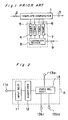
- Fig. 1 is a block diagram of a conventional recognizing and judging apparatus, which comprises a template comparator 1 having a signal input terminal 2 and a signal output terminal 3, a plurality of templates 4-7 indicative of input signal patterns prepared in advance, and a learning device 8 having a teacher signal input terminal 9.
- a series of signals representative of an object to be recognized are inputted from the signal input terminal 2 to the template comparator 1.
- the template comparator 1 compares a pattern of the inputted signals with each of the templates 4-7 and outputs the number of a template having the smallest deviation as the result of recognition from the signal output terminal 3. If the output result is incorrect, the number of a template to which the inputted signals should belong is inputted from the teacher signal input terminal 9 to the learning device 8, thereby modifying an appropriate template to improve the recognition percentage.
- the inputted signals representative of an object to be recognized are merely compared with the templates and operations are performed to obtain deviations therebetween. Accordingly, if inputted data vary, there arises a problem in that the recognition percentage would be lowered. Furthermore, because it is necessary to compare the inputted signals with all the templates, it takes very long time to perform comparisons. In addition, because it is necessary to prepare the same number of templates as the kinds of patterns to be classified and recognized, a memory having a large capacity for storing all the templates is required. In addition, learning to be performed by modifying an appropriate template needs a lot of time.
- the present invention has been developed to overcome the above-described disadvantages.
- a recognizing and judging apparatus having a network organized in a multilayered hierarchical manner comprises a given number of branched tree structures each having a plurality of layers, said given number being equal to a number of sets of characteristic data of an object to be recognized by said apparatus; and a plurality of recognition units constituting said branched tree structures and positioned in said plurality of layers, each of said recognition units comprising a signal input section to which a signal is inputted; a quantizer for quantizing said signal inputted to said signal input section; a path input section having at least one path input terminal; a path output section having at least one path output terminal; and a path selecting section operatively coupled with both said path input section and said path output section for selectively providing connection therethrough between said at least one path input terminal and said at least one path output terminal according to an output of said quantizer; a path selecting section of each of said recognition units positioned on a layer adjacent to a lowermost layer of said plurality of layers comprises a
- the path selecting section comprises a loader for changing the strength of connection between the path input terminal and the path output terminal according to the output of the quantizer.
- the path selecting section may comprise a learning device for changing the strength of connection between the path input terminal and a path output terminal indicated by the output of the quantizer.
- the learning device comprises a maximum-output-terminal detector for detecting a path output terminal from which a maximum path signal is outputted, a comparator for comparing the number of the path output terminal detected by the maximum-output-terminal detector and the number of a path output terminal indicated by the output of the quantizer, and a load increaser for increasing the strength of connection between the path input terminal and the path output terminal based on the result of comparison performed by the comparator.
- the recognizing and judging apparatus further comprises a plurality of differential measuring means for performing respective operations required to obtain differential values between signals inputted into the recognition units located on the same layer in two adjoining branched tree structures.
- a plurality of differential measuring means for performing respective operations required to obtain differential values between signals inputted into the recognition units located on the same layer in two adjoining branched tree structures.
- an output from the differential measuring means provided in each tree structure is inputted into the signal input terminals of recognition units located on the next-lower layer.
- the path input section comprises an adder for adding input signals from a plurality of the path input terminals whereas the path output section comprises a threshold processor for performing a threshold processing with respect to an output signal from the adder.
- various characteristic data of an object to be recognized are initially inputted to the signal input sections of the recognition units located on one or more upper layers. Connection paths between the recognition units located on one layer and those located on the next-lower layer are then appropriately switched according to outputs of the quantizers, thereby selectively determining desired paths leading to the lowermost layer to obtain the result of recognition.
- recognition and learning processings can be performed at a high speed.
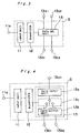
- the recognition unit comprises a signal input section 11 to which are inputted characteristic data to be recognized via a signal input terminal 11a, a quantizer 12 for quantizing the inputted characteristic data, and a path selecting section 13 for switching the connection between a path input terminal 13a 1 and path output terminals 13b 1 and 13b 2 based on a value quantized by and inputted from the quantizer 12.
- a network is organized by a combination of a plurality of recognition units, respective terminals 13a 1 , 13b 1 and 13b 2 of the recognition units are appropriately connected with one another.
- Fig. 3 schematically shows a modification of the recognition unit, in which are provided a plurality of path input terminals (in this case, two terminals 13a 1 and 13a 2 ).
- This recognition unit can be operated similarly to that shown in Fig. 2.
- a path selecting section 13 comprises a path input section 13a having one path input terminal 13a 1 , a path output section 13b having two path output terminals 13b 1 and 13b 2 , and a switch 13c operatively coupled with both the path input section 13a and the path output section (13b).
- the switch 13c switches the connection between the path input terminal 13a 1 of the path input section 13a and the path output terminals 13b 1 and 13b 2 of the path output section 13b based on a value inputted thereto from a quantizer 12.
- a path selecting section 13 comprises a path input section 13a having one path input terminal 13a 1 , a path output section 13b having two path output terminals 13b 1 and 13b 2 , and a path loading section 13d.
- Loads 13d 1 and 13d 2 are weights to be applied to path output signals, which are outputted to the path output terminals 13b 1 and 13b 2 of the path output section 13b, respectively.
- a loader 13d 0 changes these loads according to a value outputted from a quantizer 12.
- the loads 13d 1 and 13d 2 weight a path signal inputted from the path input section whereas the path output section 13b outputs weighted path signals to the path output terminals 13b 1 and 13b 2 .
- a path input section 13a comprises an adder 13a 0 for adding input signals from a plurality of path input terminals whereas a path output section 13b comprises a threshold processor 13b 0 for performing a threshold processing with respect to path signals.
- the adder 13a 0 adds path signals inputted from twelve path input terminals 13a 1 -13a 12 and inputs the result of addition to a path selector 13e.
- the path selector 13e determines how to output a signal obtained through the addition to the path output terminal according to a value outputted from a quantizer 12.
- the path selector 13e may be of either the construction as shown in Fig. 4 or that as shown in Fig. 5.
- the path selector 13e determines whether or not the path signal should be outputted in the case where the construction as shown in Fig. 4 is employed or the path selector 13e merely changes the load for weighting the path signal in the case where the construction as shown in Fig. 5 is employed.
- Fig. 7 schematically shows another modification of the recognition unit, which is generally used on a layer adjacent to the lowermost layer of a network constituting the apparatus.
- a path selecting section 13 comprises a path input section 13a having a path input terminal 13a 1 , a path output section 13b having a plurality of, for example three, output terminals 13b 1 , 13b 2 and 13b 3 , and a path loading section 13f.
- Loads 13f 1 , 13f 2 and 13f 3 are weights to be applied to path output signals, which are outputted to the path output terminals 13b 1 , 13b 2 and 13b 3 of the path output section 13b, respectively.
- a learning device 13f 4 changes the strength, indicated by a value outputted from a quantizer 12, in the connection between the path input terminal and the path output terminals.
- no signal is inputted into the quantizer 12, and the loads 13f 1 , 13f 2 and 13f 3 weight a path signal inputted from the path input section whereas the path output section 13b outputs weighted path signals to the path output terminals 13b 1 , 13b 2 and 13b 3 .
- the learning device 13f 4 comprises a maximum-output-terminal detector 13f 41 for detecting a path output terminal from which a maximum path signal is outputted, a comparator 13f 42 for comparing the number of the path output terminal detected by the maximum-output-terminal detector 13f 41 and that of the path output terminal indicated by the output value of the quantizer, and a load increaser 13f 43 for increasing the strength in the connection between the path input terminal of the path input section and the path output terminal of the path output section indicated by the output value of the quantizer on the basis of the result of comparison from the comparator 13f 42 .
- the comparator 13f 42 performs a comparison between the number of the path output terminal detected by the maximum-output-terminal detector 13f 41 and the output value of the quantizer 12, i.e., the number of a path output terminal indicated by a teacher signal.
- the comparator 13f 42 outputs "0"
- the load increaser 13f 43 increases the strength in the connection between the path input terminal of the path input section and the path output terminal of the path output section indicated by the output value of the quantizer 12.
- the comparator 13f 42 outputs "1".
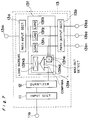
- Fig. 8 schematically shows a recognizing and judging apparatus according to a first embodiment of the present invention, in which a network is organized by appropriately connecting a plurality of recognition units in a multi-layered hierarchical structure. All the recognition units form two branched tree structures each having four layers.
- This recognizing and judging apparatus classifies objects to be recognized into three categories based on two kinds of each two characteristic data. The characteristic data to be judged are inputted into the signal input terminals 11a of recognition units positioned on first and second layers.
- the recognition unit as shown in Fig. 4 is preferably used as recognition units n11 - n12 and n21 - n24 constituting the first and second layers.
- the recognition unit as shown in Fig. 7 is preferably used as recognition units n31 - n33 constituting a third layer.
- the recognition unit as shown in Fig. 6 is preferably used as recognition units n41 - n43 constituting a fourth layer.
- the learning operation of the recognizing and judging apparatus shown in Fig. 8 is as follows.
- "1" is initially given as a path signal to the path input terminal of each of the recognition units n11 and n12 of the first layer.
- Two first characteristic data d11 and d12 of an object to be recognized are inputted into the signal input terminals leading to the quantizers of the recognition units n11 and n12 , respectively.
- the first characteristic data are quantized by the quantizers of these units n11 and n12 .
- Paths p11 and p12 are then selected by the switch shown in Fig. 4 based on respective values quantized, and the path signal "1" is sent to the path input terminal of each of the recognition units n22 and n23 of the second layer.
- two second characteristic data d21 and d22 of the object are inputted into the signal input terminals leading to the quantizers of the recognition units n21, n22 and n23, n24 , respectively.
- the second characteristic data are quantized by the quantizers of the recognition units n21, n22 and n23, n24 .
- Paths p21 and p22 are then selected by the switch shown in Fig. 4 based on respective values quantized, and the path signal "1" is sent to the path input terminal of each of the recognition units n34 and n36 positioned on the third layer.
- the loads 13f 1 , 13f 2 and 13f 3 of the recognition units n34 and n36 weight path signals inputted from respective path input sections 13a, and respective path output sections 13b output weighted path signals to the path output terminals 13b 1 , 13b 2 and 13b 3 .
- the maximum-output-terminal detector 13f 41 detects the path output terminal from which the maximum path signal is outputted and inputs the number of the path output terminal detected to the comparator 13f 42 .
- a teacher signal indicating which of three categories to be classified the object belongs to, namely, a signal indicating which of n41-n43 should be selected is inputted into the signal input terminal leading to the quantizer of each of these units.
- the comparator 13f 42 then performs a comparison between the number of the path output terminal detected by the maximum-output-terminal detector 13f 41 and the output value of the quantizer 12, i.e., the number of the path output terminal indicated by the teacher signal.
- the comparator 13f 42 inputs "0" to the load increaser 13f 43 , and the load increaser 13f 43 increases the strength in the connection between the path input terminal of the path input section and the path output terminal of the path output section indicated by the teacher signal.
- the comparator 13f 42 inputs "1" to the load increaser 13f 43 .
- connection paths between recognition units positioned on two adjoining layers are appropriately switched according to outputs of the quantizers of the recognition units organized in a multi-layered hierarchical network having the branched tree structures.
- the strength in the connection between the path input terminal of the recognition unit and the path output terminal indicated by the output value of the quantizer is changed by the learning device, thereby enabling a considerably high speed learning.
- the recognition operation is performed as follows by the apparatus according to the present invention.
- "1" is initially given as a path signal to the path input terminal of each of the recognition units n11 and n12 of the first layer.
- the two first characteristic data d11 and d12 of the object to be recognized are inputted into the signal input terminals of the quantizers of the recognition units n11 and n12 , respectively.
- the quantizers of the recognition units n11 and n12 quantize these characteristic data, and the connection paths p11 and p12 are selected by the switch shown in Fig. 4 based on values quantized.
- the path signal "1" is sent to each of the path input terminals of the recognition units n22 and n23 positioned on the second layer.
- the second characteristic data d21 and d22 of the object are inputted into the signal input terminals of the quantizers of the recognition units n21, n22 and n23, n24 , respectively, the second characteristic data are quantized by the quantizers of the recognition units n21, n22 and n23, n24 .
- the paths p21 and p22 are then selected by the switch shown in Fig. 4 based on respective values quantized, and the path signal "1" is sent to the path input terminal of each of the recognition units n34 and n36 of the third layer.
- no teacher signal is inputted to the signal input terminal of each of the recognition units n31 - n38 of the third layer.
- the state of loads during the learning is kept, and upon multiplication of the path input signals of respective recognition units by these loads, the path signals are led to the path input terminals of all the recognition units of the fourth layer.
- the adders of the recognition units of the fourth layer add the path signals inputted. Thereafter, a signal "1" is inputted into the signal input terminal of each signal input section, and the quantizer quantizes this signal so that the path selector may enable the path output. (When a signal "0" is inputted, the path selector switches so that the path output may be disabled.)
- the path signal obtained through the addition is sent to the path output section, which performs a threshold processing with respect thereto and outputs the result of the threshold processing to the path output terminal.
- Sigmoid function, Step function or the like can be used as a function for performing the threshold processing.
- connection paths between recognition units positioned on two adjoining layers are appropriately switched according to outputs of the quantizers of the recognition units organized in a multi-layered hierarchical network having the branched tree structures.
- the result of recognition can be obtained merely by determining the path signals leading to the lowermost layer based on the loads set during the learning process. Accordingly, the recognition processing can be performed at a very high speed based on the result of learning.
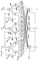
- Fig. 9 schematically shows a recognizing and judging apparatus according to a second embodiment of the present invention, in which a network is organized by appropriately connecting a plurality of recognition units in a multi-layered hierarchical structure.
- This network includes three branched tree structures t1, t2 and t3 each having four layers.
- the recognizing and judging apparatus shown in Fig. 9 classifies objects to be recognized into three categories based on three characteristic data.
- the three branched tree structures have respective differential measuring instruments s1, s2 and s3, on the first layer thereof, for performing operations required to obtain the difference between signals inputted into two adjoining recognition units positioned on the first layer.
- Outputs from the differential measuring instruments s1, s2 and s3 are inputted into signal input terminals of the corresponding recognition units of the second layer.
- the recognition unit as shown in Fig. 4 is preferably used as recognition units of the first and second layers.
- the recognition unit as shown in Fig. 5 is preferably used as recognition units of the third layer.
- the recognition unit as shown in Fig. 6 is preferably used as recognition units n41 - n43 of the fourth layer.
- the learning operation by the recognizing and judging apparatus shown in Fig. 9 is as follows.
- "1" is initially given as a path signal to the path input terminal of each of recognition units n1 , n2 and n3 of the first layer.
- Three first characteristic data d1, d2 and d3 of an object to be recognized are inputted into the signal input terminals leading to the quantizers of the recognition units n1 , n2 and n3 , respectively.
- the first characteristic data are quantized by the quantizers of these units n1 , n2 and n3 .
- Paths p12, p21 and p32 are then selected by the switch shown in Fig.
- the three differential measuring instruments s1, s2 and s3 performs operations required to obtain the difference d31 between the characteristic data d3 and d1, the difference d12 between the characteristic data d1 and d2, and the difference d23 between the characteristic data d2 and d3, respectively. These differences d31, d12 and d23 are then inputted into the signal input terminals of the quantizers of recognition units n12 , n21 and n32 of the second layer, respectively.
- the data d31, d12 and d23 are quantized by the quantizers of the recognition units n12 , n21 and n32 . Thereafter, paths p122, p212 and p321 are selected by the switch shown in Fig. 4 based on respective values quantized, and the path signal "1" is sent to the path input terminal of each of recognition units n122 , n212 and n321 positioned on the third layer. Accordingly, upon detailed investigation of the differences among the characteristic data, the recognition units of the second layer can select the appropriate paths, thereby enhancing the recognition performance of the whole apparatus.
- a teacher signal indicating which of three categories to be classified the object belongs to namely, a signal indicating which of n41-n43 should be selected is inputted into the signal input terminal leading to the quantizer of each of recognition units of the fourth layer. Based on the teacher signal, loads with respect to paths p1222, p2122 and p3212 are increased by a fixed value ⁇ .
- the characteristic data of an object to be recognized are initially inputted into the signal input sections of the recognition units positioned on the first layer.
- the differences between the characteristic data are inputted into the signal input sections of the recognition units positioned on the second layer.
- the connection paths between recognition units positioned on two adjoining layers are appropriately switched according to outputs of the quantizers of the recognition units.
- the learning processing can be performed at a very high speed.
- the recognition units of the second layer Because the outputs from the differential measuring instruments are inputted into the signal input terminals of the recognition units of the second layer, these recognition units can select the appropriate paths after the detailed investigation of the differences between the characteristic data, and therefore, the recognition performance of the whole apparatus is considerably raised. Furthermore, when an additional learning is performed, it is fundamentally sufficient if the connection paths between the recognition units are added or changed. The recognizing and judging apparatus according to the present invention is, therefore, superior in the additional learning.
- the recognition operation is performed by the apparatus shown in Fig. 9 as follows.
- the quantizers thereof quantize characteristic data inputted and change over respective switches based on outputs from the quantizers to successively select the paths p12, p21 and p32 and the paths p122, p212 and p321, as similar to the learning operation.
- no teacher signal is inputted into the signal input terminals of the recognition units n122, n212 and n321 of the third layer.
- the state of loads during the learning is kept, and upon multiplication of the path input signals of respective recognition units by these loads, the path signals are led to the path input terminals of all the recognition units of the fourth layer.
- the adders of the recognition units of the fourth layer add the path signals inputted.
- a signal "1" is inputted to the signal input terminal of each signal input section, and the quantizer quantizes this signal so that the path selector may enable the path output. (When a signal "0" is inputted, the path selector switches so that the path output may be disabled.)
- the path signal obtained through the addition is sent to the path output section, which performs a threshold processing with respect thereto and outputs the result of the threshold processing to the path output terminal.
- Sigmoid function, Step function or the like can be used as a function for performing the threshold processing.
- connection paths between the first and second layers are appropriately switched according to the outputs of the quantizers of the recognition units of the first layer.
- Characteristic data of the object which differ from those inputted into the recognition units of the first layer, are inputted into signal input sections of the recognition units of the second layer, and the connection paths between the second and third layers are appropriately switched according to the outputs of the quantizers of the recognition units positioned on the second layer.
- the result of recognition can be obtained merely by determining the path signals leading to the lowermost layer based on the loads set during the learning process. Accordingly, the recognition processing can be performed at a very high speed based on the result of learning.
- the outputs from the differential measuring instruments of the first layer are inputted into the signal input terminals of the recognition units of the next-lower layer, these recognition units can select the appropriate paths upon detailed investigation of the differences between the characteristic data. Accordingly, if the input signals vary to some extent, the recognition can be performed appropriately, thereby enhancing the performance of the whole apparatus.
Landscapes
- Engineering & Computer Science (AREA)
- Theoretical Computer Science (AREA)
- Physics & Mathematics (AREA)
- Data Mining & Analysis (AREA)
- General Health & Medical Sciences (AREA)
- Biomedical Technology (AREA)
- Biophysics (AREA)
- Computational Linguistics (AREA)
- Life Sciences & Earth Sciences (AREA)
- Evolutionary Computation (AREA)
- Artificial Intelligence (AREA)
- Molecular Biology (AREA)
- Computing Systems (AREA)
- General Engineering & Computer Science (AREA)
- General Physics & Mathematics (AREA)
- Mathematical Physics (AREA)
- Software Systems (AREA)
- Health & Medical Sciences (AREA)
- Image Analysis (AREA)
Claims (3)
- Dispositif de reconnaissance et d'évaluation comportant un réseau organisé d'une manière hiérarchique à couches multiples et comprenant :caractérisé en ce que ledit dispositif d'apprentissage (13f4) comprend un détecteur de borne de sortie maximum (13f41) afin de détecter une borne de sortie de voie à partir de laquelle un signal de voie maximum est fourni en sortie, un comparateur (13f42) destiné à comparer le numéro de la borne de sortie de voie détectée par ledit détecteur de borne de sortie maximum (13f41) et un numéro affecté a une borne de sortie de voie indiquée par la sortie dudit quantificateur (12), et un module d'augmentation de charge (13f43) destiné à augmenter une intensité de connexion entre ladite borne d'entrée de voie (13a1) et ladite borne de sortie de voie indiquée par la sortie dudit quantificateur (12) sur la base d'un résultat de comparaison exécuté par ledit comparateur (13f42).un nombre donné de structures arborescentes ramifiées (t1 à t3) comportant chacune une pluralité de couches, ledit nombre donné étant égal à un nombre d'ensembles de données de caractéristiques d'un objet à reconnaítre par ledit dispositif, etune pluralité d'unités de reconnaissance constituant lesdites structures arborescentes ramifiées (t1 à t3) et positionnées dans ladite pluralité de couches, chacune desdites unités de reconnaissance comprenant :une section d'entrée de signal (11) à laquelle un signal est appliqué en entrée,un quantificateur (12) destiné à quantifier ledit signal appliqué en entrée à ladite section d'entrée de signal (11), une section d'entrée de voie (13a) comportant au moins une borne d'entrée de voie (13a1 à 13a12), une section de sortie de voie (13b) comportant au moins une borne de sortie de voie (13b1 à 13b3), une section de sélection de voie (13c à 13f) couplée de façon fonctionnelle à la fois à ladite section d'entrée de voie (13a) et à ladite section de sortie de voie (13b) afin de réaliser sélectivement une connexion au travers de celles-ci entre ladite au moins une borne d'entrée de voie (13a1 à 13a12) et ladite au moins une borne de sortie de voie (13b1 à 13b3) conformément à une sortie dudit quantificateur (12), etune section de sélection de voie de chacune desdites unités de reconnaissance positionnées sur une couche adjacente à une couche la plus basse de ladite pluralité de couches comprenant un dispositif d'apprentissage (13f4) destiné à modifier une intensité de connexion entre ladite au moins une borne d'entrée de voie (13a1 à 13a12) et une borne de sortie de voie (13b1 à 13b3) indiquée par la sortie dudit quantificateur (12),
- Dispositif selon la revendication 1,
dans lequel ledit comparateur (13f42) fournit en sortie un premier signal lorsque le numéro affecté à la borne de sortie de voie détectée par ledit détecteur de borne de sortie maximum (13f41) ne coïncide pas avec le numéro affecté à une borne de sortie de voie indiquée par la sortie dudit quantificateur (12), et fournit en sortie un second signal lorsque les deux numéros coïncident l'un avec l'autre, et dans lequel ledit module d'augmentation de charge (13f43) augmente l'intensité de la connexion entre ladite borne d'entrée de voie (13a1) et ladite borne de sortie de voie indiquée par la sortie dudit quantificateur (12), lorsque ledit comparateur fournit en sortie ledit premier signal. - Dispositif selon la revendication 1 ou 2,
caractérisé par une pluralité de calculateurs différentiels (s1 à s3) destinée à exécuter des opérations respectives requises pour obtenir des valeurs différentielles entre des signaux reçus en entrée dans lesdites unités de reconnaissance positionnées dans la même couche dans deux structures arborescentes ramifiées adjacentes, dans lequel un calculateur différentiel (s1 à s3) est prévu dans chaque structure arborescente (t1 à t3), et une sortie de celui-ci est appliquée en entrée aux bornes d'entrée de signal (13a1) des unités de reconnaissance localisées dans la couche inférieure suivante.
Applications Claiming Priority (6)
| Application Number | Priority Date | Filing Date | Title |
|---|---|---|---|
| JP3039912A JP2684857B2 (ja) | 1991-03-06 | 1991-03-06 | 認識判断装置 |
| JP39912/91 | 1991-03-06 | ||
| JP3991291 | 1991-03-06 | ||
| JP100035/91 | 1991-05-01 | ||
| JP3100035A JP2752264B2 (ja) | 1991-05-01 | 1991-05-01 | 認識判断装置 |
| JP10003591 | 1991-05-01 |
Publications (3)
| Publication Number | Publication Date |
|---|---|
| EP0502494A2 EP0502494A2 (fr) | 1992-09-09 |
| EP0502494A3 EP0502494A3 (en) | 1993-04-28 |
| EP0502494B1 true EP0502494B1 (fr) | 1999-08-04 |
Family
ID=26379313
Family Applications (1)
| Application Number | Title | Priority Date | Filing Date |
|---|---|---|---|
| EP92103673A Expired - Lifetime EP0502494B1 (fr) | 1991-03-06 | 1992-03-04 | Appareil de reconnaissance et de jugement |
Country Status (3)
| Country | Link |
|---|---|
| US (1) | US5329594A (fr) |
| EP (1) | EP0502494B1 (fr) |
| DE (1) | DE69229687T2 (fr) |
Families Citing this family (3)
| Publication number | Priority date | Publication date | Assignee | Title |
|---|---|---|---|---|
| WO1997029437A1 (fr) * | 1996-02-09 | 1997-08-14 | Sarnoff Corporation | Procede et appareil de formation d'un reseau neuronal a la detection et la classification d'objets avec des donnees de formation incertaines |
| JP2002358523A (ja) * | 2001-05-31 | 2002-12-13 | Canon Inc | パターン認識処理装置及びその方法、画像入力装置 |
| US6641401B2 (en) * | 2001-06-20 | 2003-11-04 | Leapfrog Enterprises, Inc. | Interactive apparatus with templates |
Family Cites Families (4)
| Publication number | Priority date | Publication date | Assignee | Title |
|---|---|---|---|---|
| GB1465293A (en) * | 1973-06-15 | 1977-02-23 | Hitachi Ltd | Automatic working machine |
| JPH0634236B2 (ja) * | 1985-11-02 | 1994-05-02 | 日本放送協会 | 階層型情報処理方法 |
| US5052043A (en) * | 1990-05-07 | 1991-09-24 | Eastman Kodak Company | Neural network with back propagation controlled through an output confidence measure |
| EP0457325B1 (fr) * | 1990-05-16 | 1997-09-03 | Matsushita Electric Industrial Co., Ltd. | Unité de reconnaissance et dispositif de reconnaissance et de jugement utilisant de telles unités |
-
1992
- 1992-03-03 US US07/845,248 patent/US5329594A/en not_active Expired - Fee Related
- 1992-03-04 EP EP92103673A patent/EP0502494B1/fr not_active Expired - Lifetime
- 1992-03-04 DE DE69229687T patent/DE69229687T2/de not_active Expired - Fee Related
Also Published As
| Publication number | Publication date |
|---|---|
| DE69229687T2 (de) | 2000-04-06 |
| US5329594A (en) | 1994-07-12 |
| DE69229687D1 (de) | 1999-09-09 |
| EP0502494A3 (en) | 1993-04-28 |
| EP0502494A2 (fr) | 1992-09-09 |
Similar Documents
| Publication | Publication Date | Title |
|---|---|---|
| EP0591921B1 (fr) | Machine d'apprentissage et de reconnaissance | |
| US5255347A (en) | Neural network with learning function | |
| US5265224A (en) | Recognition unit and recognizing and judging apparatus employing same | |
| EP0502494B1 (fr) | Appareil de reconnaissance et de jugement | |
| EP0453939B1 (fr) | Méthode d'apprentissage d'un système de traitement de données | |
| EP0520446B1 (fr) | Appareil de reconnaissance et de jugement | |
| US5781128A (en) | Data compression system and method | |
| JP2779119B2 (ja) | 学習認識装置 | |
| JP2684857B2 (ja) | 認識判断装置 | |
| JP2762735B2 (ja) | 単位認識ユニット及び学習型認識判断装置 | |
| JP3337597B2 (ja) | 学習型認識判断装置 | |
| US5542005A (en) | Recognition unit and recognition apparatus | |
| JP2776265B2 (ja) | 単位認識ユニット及び学習型認識判断装置 | |
| JP2752264B2 (ja) | 認識判断装置 | |
| JP2767974B2 (ja) | 単位認識ユニット及び認識判断装置 | |
| JPH0683798A (ja) | 学習認識装置 | |
| JPH07325797A (ja) | 学習型認識判断装置 | |
| JP3344873B2 (ja) | 学習型認識判断装置 | |
| JP2574517B2 (ja) | パターン認識装置 | |
| JPH0991266A (ja) | 学習型認識判断装置 | |
| JPH056354A (ja) | 認識判断装置 | |
| JPH05225168A (ja) | 単位認識ユニット及び学習型認識判断装置 | |
| JPH10187651A (ja) | 学習型認識判断装置 | |
| Gioiello et al. | A new fully digital feed-forward neural network for hand-written digits recognition | |
| JPH07325795A (ja) | 学習型認識判断装置 |
Legal Events
| Date | Code | Title | Description |
|---|---|---|---|
| PUAI | Public reference made under article 153(3) epc to a published international application that has entered the european phase |
Free format text: ORIGINAL CODE: 0009012 |
|
| 17P | Request for examination filed |
Effective date: 19920304 |
|
| AK | Designated contracting states |
Kind code of ref document: A2 Designated state(s): DE FR GB |
|
| PUAL | Search report despatched |
Free format text: ORIGINAL CODE: 0009013 |
|
| AK | Designated contracting states |
Kind code of ref document: A3 Designated state(s): DE FR GB |
|
| 17Q | First examination report despatched |
Effective date: 19970129 |
|
| GRAG | Despatch of communication of intention to grant |
Free format text: ORIGINAL CODE: EPIDOS AGRA |
|
| GRAG | Despatch of communication of intention to grant |
Free format text: ORIGINAL CODE: EPIDOS AGRA |
|
| GRAH | Despatch of communication of intention to grant a patent |
Free format text: ORIGINAL CODE: EPIDOS IGRA |
|
| GRAH | Despatch of communication of intention to grant a patent |
Free format text: ORIGINAL CODE: EPIDOS IGRA |
|
| GRAA | (expected) grant |
Free format text: ORIGINAL CODE: 0009210 |
|
| AK | Designated contracting states |
Kind code of ref document: B1 Designated state(s): DE FR GB |
|
| REF | Corresponds to: |
Ref document number: 69229687 Country of ref document: DE Date of ref document: 19990909 |
|
| ET | Fr: translation filed | ||
| PLBE | No opposition filed within time limit |
Free format text: ORIGINAL CODE: 0009261 |
|
| STAA | Information on the status of an ep patent application or granted ep patent |
Free format text: STATUS: NO OPPOSITION FILED WITHIN TIME LIMIT |
|
| 26N | No opposition filed | ||
| REG | Reference to a national code |
Ref country code: GB Ref legal event code: IF02 |
|
| PGFP | Annual fee paid to national office [announced via postgrant information from national office to epo] |
Ref country code: GB Payment date: 20040303 Year of fee payment: 13 |
|
| PGFP | Annual fee paid to national office [announced via postgrant information from national office to epo] |
Ref country code: FR Payment date: 20040309 Year of fee payment: 13 |
|
| PGFP | Annual fee paid to national office [announced via postgrant information from national office to epo] |
Ref country code: DE Payment date: 20040311 Year of fee payment: 13 |
|
| PG25 | Lapsed in a contracting state [announced via postgrant information from national office to epo] |
Ref country code: GB Free format text: LAPSE BECAUSE OF NON-PAYMENT OF DUE FEES Effective date: 20050304 |
|
| PG25 | Lapsed in a contracting state [announced via postgrant information from national office to epo] |
Ref country code: DE Free format text: LAPSE BECAUSE OF NON-PAYMENT OF DUE FEES Effective date: 20051001 |
|
| GBPC | Gb: european patent ceased through non-payment of renewal fee |
Effective date: 20050304 |
|
| PG25 | Lapsed in a contracting state [announced via postgrant information from national office to epo] |
Ref country code: FR Free format text: LAPSE BECAUSE OF NON-PAYMENT OF DUE FEES Effective date: 20051130 |
|
| REG | Reference to a national code |
Ref country code: FR Ref legal event code: ST Effective date: 20051130 |