EP0456970B1 - Einrichtung zum kontinuierlichen Ummanteln von zylindrischen Werkstücken mit einem elastischen Material - Google Patents
Einrichtung zum kontinuierlichen Ummanteln von zylindrischen Werkstücken mit einem elastischen Material Download PDFInfo
- Publication number
- EP0456970B1 EP0456970B1 EP91102677A EP91102677A EP0456970B1 EP 0456970 B1 EP0456970 B1 EP 0456970B1 EP 91102677 A EP91102677 A EP 91102677A EP 91102677 A EP91102677 A EP 91102677A EP 0456970 B1 EP0456970 B1 EP 0456970B1
- Authority
- EP
- European Patent Office
- Prior art keywords
- shells
- semi
- cylindrical housing
- recited
- head
- Prior art date
- Legal status (The legal status is an assumption and is not a legal conclusion. Google has not performed a legal analysis and makes no representation as to the accuracy of the status listed.)
- Expired - Lifetime
Links
Images


Classifications
-
- B—PERFORMING OPERATIONS; TRANSPORTING
- B29—WORKING OF PLASTICS; WORKING OF SUBSTANCES IN A PLASTIC STATE IN GENERAL
- B29C—SHAPING OR JOINING OF PLASTICS; SHAPING OF MATERIAL IN A PLASTIC STATE, NOT OTHERWISE PROVIDED FOR; AFTER-TREATMENT OF THE SHAPED PRODUCTS, e.g. REPAIRING
- B29C48/00—Extrusion moulding, i.e. expressing the moulding material through a die or nozzle which imparts the desired form; Apparatus therefor
- B29C48/25—Component parts, details or accessories; Auxiliary operations
- B29C48/30—Extrusion nozzles or dies
- B29C48/32—Extrusion nozzles or dies with annular openings, e.g. for forming tubular articles
- B29C48/34—Cross-head annular extrusion nozzles, i.e. for simultaneously receiving moulding material and the preform to be coated
-
- B—PERFORMING OPERATIONS; TRANSPORTING
- B29—WORKING OF PLASTICS; WORKING OF SUBSTANCES IN A PLASTIC STATE IN GENERAL
- B29C—SHAPING OR JOINING OF PLASTICS; SHAPING OF MATERIAL IN A PLASTIC STATE, NOT OTHERWISE PROVIDED FOR; AFTER-TREATMENT OF THE SHAPED PRODUCTS, e.g. REPAIRING
- B29C48/00—Extrusion moulding, i.e. expressing the moulding material through a die or nozzle which imparts the desired form; Apparatus therefor
- B29C48/03—Extrusion moulding, i.e. expressing the moulding material through a die or nozzle which imparts the desired form; Apparatus therefor characterised by the shape of the extruded material at extrusion
- B29C48/09—Articles with cross-sections having partially or fully enclosed cavities, e.g. pipes or channels
-
- B—PERFORMING OPERATIONS; TRANSPORTING
- B29—WORKING OF PLASTICS; WORKING OF SUBSTANCES IN A PLASTIC STATE IN GENERAL
- B29C—SHAPING OR JOINING OF PLASTICS; SHAPING OF MATERIAL IN A PLASTIC STATE, NOT OTHERWISE PROVIDED FOR; AFTER-TREATMENT OF THE SHAPED PRODUCTS, e.g. REPAIRING
- B29C48/00—Extrusion moulding, i.e. expressing the moulding material through a die or nozzle which imparts the desired form; Apparatus therefor
- B29C48/25—Component parts, details or accessories; Auxiliary operations
- B29C48/256—Exchangeable extruder parts
- B29C48/2562—Mounting or handling of the die
Definitions
- the invention relates to a device of the type as described in the preamble of the first claim.
- Such a device is known from European Patent Application No. 0 231 976.
- metallic polygraphic rollers and the like covered with a rubber layer.
- the object is achieved in a device according to the preamble of the first claim by the features in the characterizing part.
- outlet-side end of the cylinder housing as a hinged half-shell for receiving the sleeve-like inner cone enables a very quick and easy change of the respective tool, but also a quick change of material.
- the sheathing device shown in FIG. 1 is composed of the extruder 1, which is connected to the sheathing head 3 through the flow channel 2.
- the sheathing head 3 has a degassing opening 4 on.
- a cylindrical body 5 is guided through the head 3 and thereby covered with a rubber layer 6.
- the rubber mixture prepared in the extruder passes through the flow channel 2 into the distributor space 7, in which a sleeve-shaped material distributor 8 is arranged.
- the material distributor 8 is arranged in a bearing of the housing, not shown, and has a drive gear 11 (FIG. 1) on its gear-side end.
- a pinion 12 which is driven by a motor 13, engages in the drive gear 11.
- a stationary central tube 14 is arranged coaxially in the material distributor sleeve 8, which central tube does not rotate and which is connected to the base plate by a frame-like linkage.
- an axially movable guide sleeve 26 which is held stationary during the coating process, for guiding the workpiece to be coated.
- the guide sleeve 26 is connected to a holding bracket by a linkage, not shown.
- Further guide tubes 30 to 35 are arranged in the central tube 14 for guiding the workpiece 5 to be cylindrical, in order to be able to encase workpieces of different diameters. Depending on the diameter of the workpiece 5 to be encased (FIG. 1), individual guide tubes 30-35 are removed from the head 3.
- Helical conveyor webs 17 are arranged on the back of the material distributor 8, which convey the plastic material to the outlet side of the head and distribute it uniformly over the circumference.
- a cylindrical one Housing 10 is arranged, which consists of two foldable half-shells 15 and 16 on the material outlet side of the head.
- the half-shells 15 and 16 are pivotable at their lower parting line around the bearing pin 23 and each have hinge parts 18 and 19 which engage around the bearing pin 23.
- the housing half 15 has eye bolts 20 which engage in recesses 21 for the purpose of locking the housing halves 15 and 16 and brace both housing halves against one another by means of nuts 22.
- a large ring nut 24 is provided which runs on a thread 25.
- the ring nut 24 runs circumferentially against an annular cranked stop 15a of the two housing halves 15 and 16, so that the half-shells 15 and 16 are pressed axially against the annular end face 27 and axially seal.
- An inner cone 28 is arranged in the hinged half-shells 15 and 16 and is held in the half-shells 15 and 16 by the shoulder item 36.
- the mouthpiece 29 itself is screwed to the housing halves 15 and 16 by bolts, not shown.
- a cleaning process of the head 3 is described below.
- the ring nut 24 is screwed back, for example, by a quarter turn by inserting a rod into the openings 24a and a radial rotation. This rotation causes the clamping pressure of the ring nut 24 against the stop 15a of the housing halves 15 and 16 solved.
- the inner cone 28 is freely accessible and is pulled off axially to the front, so that the rubber compound in the distributor space 7a can be pulled off from the respective guide tubes in one block.
- the cleaning of the distributor space 7a can thus be carried out very quickly, which is of crucial importance when the work is terminated or with every change of material and tools.
Description
- Die Erfindung betrifft eine Einrichtung der Gattung wie beschrieben im Oberbegriff des ersten Patentanspruchs.
- Eine derartige Einrichtung ist bekannt aus der europäischen Offenlegungsschrift Nr. 0 231 976. Mittels dieser Einrichtung werden beispielsweise metallische polygrafische Walzen u.dgl. mit einer Kautschukschicht ummantelt.
- Der Vorteil dieser Einrichtungen zum Ummanteln zylindrischer Werkstücke besteht darin, daß eine kontinuierliche Arbeitsweise durchführbar ist und daß derartig hergestellte Walzenmäntel weder in Längsrichtung noch auf ihrem Umfang Fließmarkierungen durch ein Führungsrohr haltende Dornhaltestege aufweisen.
- Nachteilig ist, daß im Falle eines Material- bzw. Werkzeugswechsels (Dimensionswechsel) der Austrittsbereich des Materialverteilerraumes nur sehr umständlich und zeitraubend gereinigt werden kann. Zu diesem Zweck muß der Kopf völlig zerlegt und somit der Belegungsvorgang für viele Stunden unterbrochen werden.
- Es ist die Aufgabe der Erfindung, im Falle eines Materialwechsels bzw. einer Produktionsunterebrechung eine schnelle und leichte Entfernung des plastischen Materials aus dem Kopf zu ermöglichen und somit ein Anvulkanisieren von z.B. Kautschuk in dem zu temperierenden Austrittsbereich zu verhindern bzw. ein leichtes Wechseln der Werkzeuge zu ermöglichen.
- Die Aufgabe wird bei einer Einrichtung gemäß dem Oberbegriff des ersten Patentanspruchs gelöst durch die Merkmale im kennzeichnenden Teil.
- Im Falle eines Materialwechsels werden
- die Verschraubungen des Mundstückes mit den Halbschalen gelöst,
- eine große Ringmutter für die axile Verspannung der Halbschalen eine Viertelumdrehung zurück geschraubt,
- die Augbolzen an der oberen axialen Teilungsfuge der Halbschalen gelöst und weggeschwenkt, dann können
- die Halbschalen selbst um ein unteres Scharnier geschwenkt werden,
- der somit freiliegende hülsenförmige Innenkonus wird nach vorne abgezogen
- Somit wird durch die Ausbildung des austrittsseitigen Endes des Zylindergehäuses als aufklappbare Halbschalen für die Aufnahme des hülsenartigen Innenkonusses ein sehr schneller und problemloser Wechsel des jeweiligen Werkzeuges aber auch ein schneller Materiawechsel ermöglicht.
- Ein Ausführungsbeispiel der Erfindung wird in den Zeichnungen gezeigt und nachfolgend erläutert.
- Es zeigen:
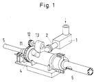
- Fig. 1
- eine perspektivische Ansicht einer Einrichtung zum Ummanteln von zylindrischen Körpern.
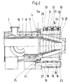
- Fig. 2
- einen Längsschnitt durch einen Ummantelungskopf gemäß der Erfindung.
- Fig. 3
- eine Draufsicht auf den Kopf, wie gezeigt in Fig. 2.
- Fig. 4
- einen Querschnitt des Kopfes im geschlossenen und aufgeklappten Zustand.
- Die in Fig. 1 gezeigte Ummantelungseinrichtung setzt sich zusammen aus dem Extruder 1, der durch den Fließkanal 2 mit dem Ummantelungskopf 3 verbunden ist. Der Ummantelungskopf 3 weist eine Entgasungsöffnung 4 auf. Durch den Kopf 3 wird ein zylindrischer Körper 5 geführt und dabei mit einer Kautschukschicht 6 ummantelt.
- Die im Extruder aufbereitete Kautschukmischung gelangt durch den Fließkanal 2 in den Verteilerraum 7, in dem ein hülsenförmig ausgebildeter Materialverteiler 8 angeordnet ist.
- Der Materialverteiler 8 ist in einem nicht dargestellten Lager des Gehäuses angeordnet und weist auf seinem getriebeseitigen Ende ein Antriebszahnrad 11 (Fig. 1) auf. In das Antriebszahnrad 11 greift ein Ritzel 12 ein, welches von einem Motor 13 angetrieben wird.
- In der Materialverteilerhülse 8 ist koaxial eine stationäre Zentralrohr 14 angeordnet, das nicht mitrotiert und das durch ein rahmenartiges Gestänge mit der Bodenplatte verbunden ist. In dem Zentralrohr 14 ist wiederum eine axial zwar bewegliche, aber beim Belegungsvorgang stationär gehaltene Führungshülse 26 angeordnet, für die Führung des zu belegenden Werkstückes. Die Führungshülse 26 wird durch ein nicht dargestelltes Gestänge mit einer Haltekonsole verbunden.
- In dem Zentralrohr 14 für die Führung des zlindrisch zu ummantelnden Werkstückes 5 sind weitere Führungsrohre 30 bis 35 angeordnet, um jeweils Werkstücke unterschiedlichster Durchmesser ummantelns zu können. Je nach dem Durchmesser des zu ummantelnden Werkstückes 5 (Fig. 1) werden einzelne Führungsrohre 30 - 35 aus dem Kopf 3 entfernt.
- Auf dem Rücken des Materialverteilers 8 sind wendelförmige Förderstege 17 angeordnet, welche das plastische Material zur Austrittsseite des Kopfes fördern und umfangsmäßig gleichmäßig verteilen.
- Um die rotierende und fördernde Materialverteilerhülse 8 ist ein zylinderförmiges Gehäuse 10 angeordnet, welches an der Materialaustrittsseite des Kopfes aus zwei klappbaren Halbschalen 15 und 16 besteht.
- Die Halbschalen 15 und 16 sind an ihrer unteren Trennfuge um den Lagerbolzen 23 verschwenkbar und weisen jeweils Scharnierteile 18 und 19 auf, die um den Lagerbolzen 23 greifen.
- An ihrer oberen Trennfuge weist die Gehäusehälfte 15 Augbolzen 20 auf, die zwecks Verriegelung der Gehäusehälften 15 und 16 in Aussparungen 21 eingreifen und mittels Muttern 22 beide Gehäusehälften gegeneinander verspannen.
- Um die radial gegeneinander verspannten Halbschalen 15 und 16 auch axial gegen das Zylindergehäuse 10 verspannen zu können, wird eine große Ringmutter 24 vorgesehen, die auf einem Gewinde 25 läuft. Die Ringmutter 24 läuft umfangmäßig gegen einen ringförmigen ausgekröpften Anschlag 15a der beiden Gehäusehälften 15 und 16, so daß die Halbschalen 15 und 16 in axialer Richtung gegen die ringförmige Stirnfläche 27 angepreßt werden und axial abdichten.
- In den aufklappbaren Halbschalen 15 und 16 ist ein Innenkonus 28 angeordnet, der durch die Schulter Pos. 36 in den Halbschalben 15 und 16 gehalten wird. Das Mundstück 29 selbst wird durch nicht gezeigte Bolzen mit den Gehäusehälftn 15 und 16 verschraubt.
- Nachfolgend wird ein Reinigungsvorgang des Kopfes 3 beschrieben.
- Zunächst wird die Ringmutter 24 z.B. durch eine Viertelumdrehung zurückgeschraubt durch Einsetzen einer Stange in die Öffnungen 24a und einer radialen Drehung. Durch diese Drehung wird der Spanndruck der Ringmutter 24 gegen den Anschlag 15a der Gehäusehälften 15 und 16 gelöst.
- Dann wird das Mundstück 29 von den Halbschalen 15 und 16 abgeschraubt. Anschließend werden die Muttern 22 der Augbolzen 20 gelöst, um die Augbolzen 20 aus den Aussparungen 21 nach oben herausschwenken zu können, so daß die beiden Gehäusehälften 15 und 16 in die in Fig. 4 gezeigte Position heruntergeschwenkt werden können.
- Danach ist dann der Innenkonus 28 frei zugänglich und wird axial nach vorne abgezogen, so daß die Kautschukmasse in dem Verteilerraum 7a von den jeweiligen Führungsrohren in einem Block abgezogen werden kann. Die Reinigung des Verteilerraumes 7a ist somit sehr schnell durchführbar, was von entscheidender Bedeutung ist bei einer Arbeitsbeendigung bzw. bei jedem Material- und Werkzeugwechsel.
und der Materialpfropfen auf dem Ausformungsrohr ist frei zugänglich. Das in den Gängen der Materialverteilerhülse sich befindende Material wird durch die Drehung der Hülse nach vorne gefördert, so daß auch dieser Bereich frei von Material ist.
Claims (4)
- Einrichtung zum kontinuierlichen Ummanteln von zylindrischen Werkstücken mit einer Mischung aus Kautschuk oder thermoplastischem Kunststoff, bestehend aus einem Extruder (1) zum Plastifizieren der Mischung und einem Ummantelungskopf (3) sowie einem beide Maschinen miteinander verbindenden Fließkanal (2), wobei der Ummantelungskopf (3) durch ein Zylindergehäuse (10) gebildet wird, mit darin rotierender Materialverteilerhülse (8) auf deren Rücken wendelförmige Förderstege (17) angeordnet sind und mit einem koaxial in der Materialverteilerhülse angeordneten stationären Zentralrohr (14) für die Führung des zu ummantelnden Werkstückes,
dadurch gekennzeichnet,
daß das austrittsseitige Ende des Zylindergehäuses (10) durch, einen auswechselbaren Innenkonus (28) aufnehmende, aufklappbare Halbschalen (15, 16) gebildet wird. - Einrichtung nach Anspruch 1,
dadurch gekennzeichnet,
daß die Halbschalen (15, 16) radial gegeneinander und axial gegen das Zylindergehäuse (10) verspannbar ausgebildet sind. - Einrichtung nach Anspruch 1,
dadurch gekennzeichnet,
daß die Halbschalen (15, 16) an der einen Seite ihrer axialen Längstrennfuge durch ein Scharnier (18, 19, 23) miteinander verbunden sind und an der anderen Seite ihrer axialen Längstrennfuge mittels verschwankbarer Augbolzen (20, 22) arretierbar und gegeneinander verspannbar ausgebildet sind. - Einrichtung nach den Ansprüchen 1 und 2,
dadurch gekennzeichnet,
daß die axiale Verspanneinrichtung der Halbschalen (15, 16) durch eine die Halbschalen (15, 16) gegen das Kopfgehäuse (9) pressende, auf einem Außengewinde (25) des Zylindergehäuses (10) laufende, gegen einen Anschlag (15a) der Halbschalen (15, 16) drehbare Ringmutter (24) gebildet wird.
Applications Claiming Priority (2)
| Application Number | Priority Date | Filing Date | Title |
|---|---|---|---|
| DE4015863 | 1990-05-17 | ||
| DE4015863A DE4015863C1 (en) | 1990-05-17 | 1990-05-17 | Appts. to continuously surround cylindrical workpieces with rubber etc - has extruder to plasticise mixt., mantle head and flow channel to connect machines |
Publications (3)
| Publication Number | Publication Date |
|---|---|
| EP0456970A2 EP0456970A2 (de) | 1991-11-21 |
| EP0456970A3 EP0456970A3 (en) | 1992-03-18 |
| EP0456970B1 true EP0456970B1 (de) | 1994-07-20 |
Family
ID=6406616
Family Applications (1)
| Application Number | Title | Priority Date | Filing Date |
|---|---|---|---|
| EP91102677A Expired - Lifetime EP0456970B1 (de) | 1990-05-17 | 1991-02-23 | Einrichtung zum kontinuierlichen Ummanteln von zylindrischen Werkstücken mit einem elastischen Material |
Country Status (3)
| Country | Link |
|---|---|
| EP (1) | EP0456970B1 (de) |
| JP (1) | JPH04229221A (de) |
| DE (2) | DE4015863C1 (de) |
Families Citing this family (5)
| Publication number | Priority date | Publication date | Assignee | Title |
|---|---|---|---|---|
| FR2687095B1 (fr) * | 1992-02-06 | 1995-06-09 | Vetrotex France Sa | Procede de fabrication d'un fil composite et produits composites obtenus a partir dudit fil. |
| FR2687094A1 (fr) * | 1992-02-06 | 1993-08-13 | Vetrotex France Sa | Dispositif de gainage d'un materiau filiforme par une matiere a l'etat fondu. |
| US5601646A (en) * | 1995-05-26 | 1997-02-11 | Alcatel Na Cable Systems, Inc. | Apparatus for applying gel to a plurality of optical fibers |
| AT3318U1 (de) * | 1998-09-29 | 2000-01-25 | Technoplast Kunststofftechnik | Vorrichtung zum extrudieren von kunststoffrohren oder profilen |
| CN111438913A (zh) * | 2020-05-26 | 2020-07-24 | 昆明智旺实业有限公司 | 一种便于改变挤出形状的熔融塑料挤出设备用出料机构 |
Family Cites Families (8)
| Publication number | Priority date | Publication date | Assignee | Title |
|---|---|---|---|---|
| US2057043A (en) * | 1934-09-29 | 1936-10-13 | Farrel Birmingham Co Inc | Attaching means for tube machine closures |
| DE1809470A1 (de) * | 1968-11-18 | 1970-06-11 | Karl Marx Stadt Maschf | Schalenverschluss,vorzugsweise zur Befestigung eines Spritzwerkzeuges an einer Schneckenpresse |
| US3833247A (en) * | 1973-03-15 | 1974-09-03 | Royle & Sons J | Breech-lock mechanism for extrusion apparatus |
| JPS582059B2 (ja) * | 1979-11-07 | 1983-01-13 | 古河電気工業株式会社 | 押出機クロスヘツド |
| JPS5859827A (ja) * | 1981-10-07 | 1983-04-09 | Furukawa Electric Co Ltd:The | 押出機のニツプル・ダイス交換装置 |
| EP0095010A1 (de) * | 1982-05-25 | 1983-11-30 | Luigi Bartoli | Isolierrohr für unterirdische Verwendung, Verfahren zu seiner Herstellung und Vorrichtung zur Durchführung des Verfahrens |
| JPS62153101A (ja) * | 1985-12-26 | 1987-07-08 | Ishikawatoki Tekkosho:Kk | 真空ロツク式押出機 |
| DK173158B1 (da) * | 1986-01-30 | 2000-02-14 | Viradan As | Ekstruderkrydshoved til pålægning af uvulkaniseret gummimasse eller lignende på et cylindrisk emne |
-
1990
- 1990-05-17 DE DE4015863A patent/DE4015863C1/de not_active Expired - Lifetime
-
1991
- 1991-02-23 EP EP91102677A patent/EP0456970B1/de not_active Expired - Lifetime
- 1991-02-23 DE DE59102222T patent/DE59102222D1/de not_active Expired - Fee Related
- 1991-05-16 JP JP3111942A patent/JPH04229221A/ja not_active Withdrawn
Also Published As
| Publication number | Publication date |
|---|---|
| EP0456970A3 (en) | 1992-03-18 |
| JPH04229221A (ja) | 1992-08-18 |
| DE4015863C1 (en) | 1991-03-07 |
| EP0456970A2 (de) | 1991-11-21 |
| DE59102222D1 (de) | 1994-08-25 |
Similar Documents
| Publication | Publication Date | Title |
|---|---|---|
| EP1620246B1 (de) | Mehrwellenextruder | |
| DE2600648A1 (de) | Pelletpresse | |
| DE4305202A1 (en) | Injection moulding machine with plasticator feeding injector chamber - has side bore leading from injector chamber to nozzle to prevent any portion of shot from remaining un-injected and hence affected thermally | |
| DE102007058174A1 (de) | Extruder | |
| EP0456970B1 (de) | Einrichtung zum kontinuierlichen Ummanteln von zylindrischen Werkstücken mit einem elastischen Material | |
| DE1960269A1 (de) | Maschine und Vorrichtung zum Formen von Behaeltern aus Kunststoff | |
| DE2003282C3 (de) | Extruderkopf | |
| EP0814947B1 (de) | Extrusionskopf für kunststoffextruder | |
| DE19719220C2 (de) | Querspritzkopf einer Extrusionsanlage | |
| DE2352638A1 (de) | Vorrichtung zum reinigen von fuer die herstellung von betonrohren verwendeten giesscheiben | |
| DE822261C (de) | Spritzmaschine zum Erzeugen von gestreiften Isolierstoffmaenteln auf elektrischen Leitern oder zur Herstellung von gestreiften Schlaeuchen oder aehnlichen fortlaufenden hohlen oder vollen Gebilden | |
| DE1679803B1 (de) | Vorrichtung zum unterwasser-granulieren von thermoplastischem material | |
| EP0400281A2 (de) | Einrichtung zum kontinuierlichen Ummanteln von zylindrischen Werkstücken mit einem elastischen Material | |
| DE3907866C2 (de) | ||
| WO2019206486A1 (de) | Spritzgiessmaschine mit einer einen kanal für ein fluid aufweisenden indexwelle | |
| EP3153296B1 (de) | Spritzkopf für eine vorrichtung zur herstellung eines verbundrohres | |
| EP1261472A1 (de) | Vorrichtung und verfahren zur herstellung von hohlkörpern aus kunststoff | |
| EP1462014A1 (de) | Vorrichtung zum Entfernen von Fremdstoffen aus Tabak | |
| EP3392013B1 (de) | Injektor, vorderteil für einen injektor, verfahren und produktionsanlage zur herstellung von formteilen aus kunststoff | |
| EP0583508A1 (de) | Verfahren und Vorrichtung zum automatischen Schliessen Verriegeln und Öffnen einer geteilten Giessform zum Herstellen von Kunststoffartikeln | |
| DE3046113A1 (de) | Kuehlvorrichtung an einer stranggiessmaschine | |
| DE2626560A1 (de) | Handschweissgeraet | |
| DE19720819B4 (de) | Planetwalzenextruder in Modulbauweise | |
| EP0127736A1 (de) | Presse zum Erzeugen von Pellets aus Schüttgut | |
| DE1907387B1 (de) | Strangpresskopf zum Herstellen eines aus zwei konzentrischen Schichten bestehenden Kunststoffrohres |
Legal Events
| Date | Code | Title | Description |
|---|---|---|---|
| PUAI | Public reference made under article 153(3) epc to a published international application that has entered the european phase |
Free format text: ORIGINAL CODE: 0009012 |
|
| AK | Designated contracting states |
Kind code of ref document: A2 Designated state(s): DE DK FR GB IT NL SE |
|
| PUAL | Search report despatched |
Free format text: ORIGINAL CODE: 0009013 |
|
| AK | Designated contracting states |
Kind code of ref document: A3 Designated state(s): DE DK FR GB IT NL SE |
|
| 17P | Request for examination filed |
Effective date: 19920212 |
|
| 17Q | First examination report despatched |
Effective date: 19931126 |
|
| ITF | It: translation for a ep patent filed |
Owner name: DE DOMINICIS & MAYER S.R.L. |
|
| GRAA | (expected) grant |
Free format text: ORIGINAL CODE: 0009210 |
|
| AK | Designated contracting states |
Kind code of ref document: B1 Designated state(s): DE DK FR GB IT NL SE |
|
| REF | Corresponds to: |
Ref document number: 59102222 Country of ref document: DE Date of ref document: 19940825 |
|
| GBT | Gb: translation of ep patent filed (gb section 77(6)(a)/1977) |
Effective date: 19940819 |
|
| ET | Fr: translation filed | ||
| EAL | Se: european patent in force in sweden |
Ref document number: 91102677.1 |
|
| PG25 | Lapsed in a contracting state [announced via postgrant information from national office to epo] |
Ref country code: GB Effective date: 19950223 Ref country code: DK Effective date: 19950223 |
|
| PG25 | Lapsed in a contracting state [announced via postgrant information from national office to epo] |
Ref country code: SE Effective date: 19950224 |
|
| PLBE | No opposition filed within time limit |
Free format text: ORIGINAL CODE: 0009261 |
|
| STAA | Information on the status of an ep patent application or granted ep patent |
Free format text: STATUS: NO OPPOSITION FILED WITHIN TIME LIMIT |
|
| 26N | No opposition filed | ||
| PG25 | Lapsed in a contracting state [announced via postgrant information from national office to epo] |
Ref country code: NL Effective date: 19950901 |
|
| GBPC | Gb: european patent ceased through non-payment of renewal fee |
Effective date: 19950223 |
|
| PG25 | Lapsed in a contracting state [announced via postgrant information from national office to epo] |
Ref country code: FR Effective date: 19951031 |
|
| NLV4 | Nl: lapsed or anulled due to non-payment of the annual fee |
Effective date: 19950901 |
|
| EUG | Se: european patent has lapsed |
Ref document number: 91102677.1 |
|
| PGFP | Annual fee paid to national office [announced via postgrant information from national office to epo] |
Ref country code: DE Payment date: 19951202 Year of fee payment: 6 |
|
| REG | Reference to a national code |
Ref country code: FR Ref legal event code: ST |
|
| PG25 | Lapsed in a contracting state [announced via postgrant information from national office to epo] |
Ref country code: DE Effective date: 19971101 |
|
| PG25 | Lapsed in a contracting state [announced via postgrant information from national office to epo] |
Ref country code: IT Free format text: LAPSE BECAUSE OF NON-PAYMENT OF DUE FEES;WARNING: LAPSES OF ITALIAN PATENTS WITH EFFECTIVE DATE BEFORE 2007 MAY HAVE OCCURRED AT ANY TIME BEFORE 2007. THE CORRECT EFFECTIVE DATE MAY BE DIFFERENT FROM THE ONE RECORDED. Effective date: 20050223 |