EP0456483B1 - Bande d'étanchéité moulée et appareil et procédé pour sa fabrication - Google Patents
Bande d'étanchéité moulée et appareil et procédé pour sa fabrication Download PDFInfo
- Publication number
- EP0456483B1 EP0456483B1 EP91304156A EP91304156A EP0456483B1 EP 0456483 B1 EP0456483 B1 EP 0456483B1 EP 91304156 A EP91304156 A EP 91304156A EP 91304156 A EP91304156 A EP 91304156A EP 0456483 B1 EP0456483 B1 EP 0456483B1
- Authority
- EP
- European Patent Office
- Prior art keywords
- rubber
- hybrid
- weather strip
- ports
- molding
- Prior art date
- Legal status (The legal status is an assumption and is not a legal conclusion. Google has not performed a legal analysis and makes no representation as to the accuracy of the status listed.)
- Expired - Lifetime
Links
Images


Classifications
-
- B—PERFORMING OPERATIONS; TRANSPORTING
- B60—VEHICLES IN GENERAL
- B60R—VEHICLES, VEHICLE FITTINGS, OR VEHICLE PARTS, NOT OTHERWISE PROVIDED FOR
- B60R13/00—Elements for body-finishing, identifying, or decorating; Arrangements or adaptations for advertising purposes
- B60R13/06—Sealing strips
-
- B—PERFORMING OPERATIONS; TRANSPORTING
- B29—WORKING OF PLASTICS; WORKING OF SUBSTANCES IN A PLASTIC STATE IN GENERAL
- B29C—SHAPING OR JOINING OF PLASTICS; SHAPING OF MATERIAL IN A PLASTIC STATE, NOT OTHERWISE PROVIDED FOR; AFTER-TREATMENT OF THE SHAPED PRODUCTS, e.g. REPAIRING
- B29C48/00—Extrusion moulding, i.e. expressing the moulding material through a die or nozzle which imparts the desired form; Apparatus therefor
- B29C48/03—Extrusion moulding, i.e. expressing the moulding material through a die or nozzle which imparts the desired form; Apparatus therefor characterised by the shape of the extruded material at extrusion
- B29C48/07—Flat, e.g. panels
-
- B—PERFORMING OPERATIONS; TRANSPORTING
- B29—WORKING OF PLASTICS; WORKING OF SUBSTANCES IN A PLASTIC STATE IN GENERAL
- B29C—SHAPING OR JOINING OF PLASTICS; SHAPING OF MATERIAL IN A PLASTIC STATE, NOT OTHERWISE PROVIDED FOR; AFTER-TREATMENT OF THE SHAPED PRODUCTS, e.g. REPAIRING
- B29C48/00—Extrusion moulding, i.e. expressing the moulding material through a die or nozzle which imparts the desired form; Apparatus therefor
- B29C48/03—Extrusion moulding, i.e. expressing the moulding material through a die or nozzle which imparts the desired form; Apparatus therefor characterised by the shape of the extruded material at extrusion
- B29C48/09—Articles with cross-sections having partially or fully enclosed cavities, e.g. pipes or channels
- B29C48/11—Articles with cross-sections having partially or fully enclosed cavities, e.g. pipes or channels comprising two or more partially or fully enclosed cavities, e.g. honeycomb-shaped
-
- B—PERFORMING OPERATIONS; TRANSPORTING
- B29—WORKING OF PLASTICS; WORKING OF SUBSTANCES IN A PLASTIC STATE IN GENERAL
- B29C—SHAPING OR JOINING OF PLASTICS; SHAPING OF MATERIAL IN A PLASTIC STATE, NOT OTHERWISE PROVIDED FOR; AFTER-TREATMENT OF THE SHAPED PRODUCTS, e.g. REPAIRING
- B29C48/00—Extrusion moulding, i.e. expressing the moulding material through a die or nozzle which imparts the desired form; Apparatus therefor
- B29C48/03—Extrusion moulding, i.e. expressing the moulding material through a die or nozzle which imparts the desired form; Apparatus therefor characterised by the shape of the extruded material at extrusion
- B29C48/12—Articles with an irregular circumference when viewed in cross-section, e.g. window profiles
-
- B—PERFORMING OPERATIONS; TRANSPORTING
- B29—WORKING OF PLASTICS; WORKING OF SUBSTANCES IN A PLASTIC STATE IN GENERAL
- B29C—SHAPING OR JOINING OF PLASTICS; SHAPING OF MATERIAL IN A PLASTIC STATE, NOT OTHERWISE PROVIDED FOR; AFTER-TREATMENT OF THE SHAPED PRODUCTS, e.g. REPAIRING
- B29C48/00—Extrusion moulding, i.e. expressing the moulding material through a die or nozzle which imparts the desired form; Apparatus therefor
- B29C48/16—Articles comprising two or more components, e.g. co-extruded layers
- B29C48/18—Articles comprising two or more components, e.g. co-extruded layers the components being layers
- B29C48/19—Articles comprising two or more components, e.g. co-extruded layers the components being layers the layers being joined at their edges
-
- B—PERFORMING OPERATIONS; TRANSPORTING
- B29—WORKING OF PLASTICS; WORKING OF SUBSTANCES IN A PLASTIC STATE IN GENERAL
- B29C—SHAPING OR JOINING OF PLASTICS; SHAPING OF MATERIAL IN A PLASTIC STATE, NOT OTHERWISE PROVIDED FOR; AFTER-TREATMENT OF THE SHAPED PRODUCTS, e.g. REPAIRING
- B29C48/00—Extrusion moulding, i.e. expressing the moulding material through a die or nozzle which imparts the desired form; Apparatus therefor
- B29C48/16—Articles comprising two or more components, e.g. co-extruded layers
- B29C48/18—Articles comprising two or more components, e.g. co-extruded layers the components being layers
- B29C48/21—Articles comprising two or more components, e.g. co-extruded layers the components being layers the layers being joined at their surfaces
-
- B—PERFORMING OPERATIONS; TRANSPORTING
- B29—WORKING OF PLASTICS; WORKING OF SUBSTANCES IN A PLASTIC STATE IN GENERAL
- B29C—SHAPING OR JOINING OF PLASTICS; SHAPING OF MATERIAL IN A PLASTIC STATE, NOT OTHERWISE PROVIDED FOR; AFTER-TREATMENT OF THE SHAPED PRODUCTS, e.g. REPAIRING
- B29C48/00—Extrusion moulding, i.e. expressing the moulding material through a die or nozzle which imparts the desired form; Apparatus therefor
- B29C48/25—Component parts, details or accessories; Auxiliary operations
- B29C48/30—Extrusion nozzles or dies
- B29C48/304—Extrusion nozzles or dies specially adapted for bringing together components, e.g. melts within the die
-
- B—PERFORMING OPERATIONS; TRANSPORTING
- B60—VEHICLES IN GENERAL
- B60J—WINDOWS, WINDSCREENS, NON-FIXED ROOFS, DOORS, OR SIMILAR DEVICES FOR VEHICLES; REMOVABLE EXTERNAL PROTECTIVE COVERINGS SPECIALLY ADAPTED FOR VEHICLES
- B60J10/00—Sealing arrangements
- B60J10/15—Sealing arrangements characterised by the material
-
- Y—GENERAL TAGGING OF NEW TECHNOLOGICAL DEVELOPMENTS; GENERAL TAGGING OF CROSS-SECTIONAL TECHNOLOGIES SPANNING OVER SEVERAL SECTIONS OF THE IPC; TECHNICAL SUBJECTS COVERED BY FORMER USPC CROSS-REFERENCE ART COLLECTIONS [XRACs] AND DIGESTS
- Y10—TECHNICAL SUBJECTS COVERED BY FORMER USPC
- Y10T—TECHNICAL SUBJECTS COVERED BY FORMER US CLASSIFICATION
- Y10T428/00—Stock material or miscellaneous articles
- Y10T428/24—Structurally defined web or sheet [e.g., overall dimension, etc.]
- Y10T428/2419—Fold at edge
- Y10T428/24198—Channel-shaped edge component [e.g., binding, etc.]
-
- Y—GENERAL TAGGING OF NEW TECHNOLOGICAL DEVELOPMENTS; GENERAL TAGGING OF CROSS-SECTIONAL TECHNOLOGIES SPANNING OVER SEVERAL SECTIONS OF THE IPC; TECHNICAL SUBJECTS COVERED BY FORMER USPC CROSS-REFERENCE ART COLLECTIONS [XRACs] AND DIGESTS
- Y10—TECHNICAL SUBJECTS COVERED BY FORMER USPC
- Y10T—TECHNICAL SUBJECTS COVERED BY FORMER US CLASSIFICATION
- Y10T428/00—Stock material or miscellaneous articles
- Y10T428/24—Structurally defined web or sheet [e.g., overall dimension, etc.]
- Y10T428/24744—Longitudinal or transverse tubular cavity or cell
-
- Y—GENERAL TAGGING OF NEW TECHNOLOGICAL DEVELOPMENTS; GENERAL TAGGING OF CROSS-SECTIONAL TECHNOLOGIES SPANNING OVER SEVERAL SECTIONS OF THE IPC; TECHNICAL SUBJECTS COVERED BY FORMER USPC CROSS-REFERENCE ART COLLECTIONS [XRACs] AND DIGESTS
- Y10—TECHNICAL SUBJECTS COVERED BY FORMER USPC
- Y10T—TECHNICAL SUBJECTS COVERED BY FORMER US CLASSIFICATION
- Y10T428/00—Stock material or miscellaneous articles
- Y10T428/24—Structurally defined web or sheet [e.g., overall dimension, etc.]
- Y10T428/24942—Structurally defined web or sheet [e.g., overall dimension, etc.] including components having same physical characteristic in differing degree
- Y10T428/24983—Hardness
-
- Y—GENERAL TAGGING OF NEW TECHNOLOGICAL DEVELOPMENTS; GENERAL TAGGING OF CROSS-SECTIONAL TECHNOLOGIES SPANNING OVER SEVERAL SECTIONS OF THE IPC; TECHNICAL SUBJECTS COVERED BY FORMER USPC CROSS-REFERENCE ART COLLECTIONS [XRACs] AND DIGESTS
- Y10—TECHNICAL SUBJECTS COVERED BY FORMER USPC
- Y10T—TECHNICAL SUBJECTS COVERED BY FORMER US CLASSIFICATION
- Y10T428/00—Stock material or miscellaneous articles
- Y10T428/29—Coated or structually defined flake, particle, cell, strand, strand portion, rod, filament, macroscopic fiber or mass thereof
- Y10T428/2902—Channel shape
Definitions
- the present invention relates to a moulded weather strip and an apparatus and process for manufacturing the same.
- molding E comprises a first portion E1 formed of hard rubber, a second portion E2 formed of a soft or sponge rubber, and a third portion E3 formed of semihard rubber having less flexibility than the sponge rubber but more than the hard rubber.
- portions E1, E2 and E3 are generally simultaneously and integrally formed as a unit.
- a problem usually associated with such a molding E is that three types of rubber have to be prepared to form the molding E.
- apparatus for manufacturing the molding has to include three special purpose machines to extrude hard rubber, sponge rubber and semihard rubber in order to form the molding E, thereby increasing the cost of such apparatus.
- DE-A-3229554 discloses a molding comprising a portion formed of a first polymer A, a portion formed of a second different polymer B and an hybrid portion H, V formed of the two polymers A, B.
- the difference between the polymers A, B is that they are, in part, incompatible in terms of adhesion.
- a method is disclosed which enables adhesively incompatible polymers to be coextruded without the need for a special, adhesion-promoting substance to be positioned at the interface between the two different polymers. Instead of such a substance, there is used a coupling layer consisting of the two polymers to be joined.
- a moulded weather strip comprising a portion formed of harder rubber, a portion formed of softer rubber and an hybrid portion formed of an hybrid of the two rubbers.
- a moulded weather strip manufacturing process comprising a portion formed of harder rubber, a portion formed of softer rubber and an hybrid portion formed of an hybrid of both rubbers, the process comprising the steps of: providing a molding die having an extrusion opening and at least three flow conduits communicating with said extrusion opening; simultaneously feeding compositions to form the harder and softer materials into said molding die; introducing a part of the composition to form the harder rubber into the first flow conduit of said molding die and extruding it to form the portion formed of the harder rubber; introducing a part of the composition to form the softer rubber into the second flow conduit of said molding die and extruding it to form the portion formed of the softer rubber; and introducing the remainder of the two compositions into the third conduit of said molding die to form an hybrid of the two rubbers and extruding the hybrid from said extrusion opening to form the hybrid portion.
- a moulded weather strip manufacturing apparatus for manufacturing a moulded weather strip including portions of three different hardness rubbers, the apparatus comprising: a first feed pipe for feeding a composition to form a harder rubber; a second feed pipe for feeding a composition to form a softer rubber; and a molding die having an extrusion opening and at least three flow conduits communicating with said extrusion opening, the first flow conduit communicating with said first feed pipe, the second flow conduit communicating with said second feed pipe and the third flow conduit communicating with both of said first and second feed pipes, whereby a hybrid of the two compositions is formed in said third flow conduit when the two compositions are fed from said first and second feed pipes.
- the present invention therefore provides a molding formed of only two types of rubber but includes three portions having different flexibility, and apparatus for its production.
- the apparatus for producing the molding does not need a dedicated machine to extrude semihard rubber, the cost of the apparatus is remarkably decreased.
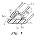
- a hollow molding M comprises a first portion M1 formed of hard rubber R1, a second portion M2 formed of soft (hereinafter referred to as sponge) rubber R2, and a third portion M3 formed of hybrid R3 of the hard rubber R1 and the sponge rubber R2 of which the flexibility is less than that of the sponge rubber R2 but greater than that of the hard rubber R1.
- These three portions M1, M2, M3 are integrally formed as a unit.
- the second and third portions M2, M3 cooperate with each other to form a sectionally arcuate portion.
- the arucuate portion is connected to the first portion M1 to form a sectionally semicircular bore B therebetween.
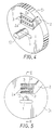
- FIGS. 2 to 13 shown therein is apparatus for manufacturing the molding M.
- the apparatus includes a molding die D comprising a first disk-like molding die part D1, a second disk-like molding die part D2 and a third disk-like molding die part D3 which are closely positioned in this order.
- the first die part D1 is centrally formed with a long opening 1 through which the hard rubber R1 is to be supplied.
- the opening 1 is configured substantially to the sectional configuration of the first portion M1 of the molding M.
- the first die part D1 is also provided with a core member 10 which is positioned adjacent to the opening 1 and is forwardly projected from the front surface of the die part D1.
- the sectional configuration of the core member 10 is configured substantially to the sectional configuration of the bore B of the molding M.
- the upper position of the die part D1 is formed with a groove 2 through which the sponge rubber R2 is to be supplied. As best shown in FIG. 5, the groove 2 is branched to three thin grooves 2a.
- the die part D1 is also formed with a plurality of through holes 3 into which the hard rubber is to be introduced. The through holes 3 are arranged in two rows each of which is positioned between the thin grooves 2a.
- the second die part D2 is formed with an opening 4 which is adapted to closely receive the core member 10 therein.
- the die part D2 is also formed with an opening 5 which communicates with the opening 4 at the upper side thereof and has a configuration identical with that of the opening 1 of the first die part D1.
- the rear surface of the die part D2 is formed with a tapered recess 6 which is to be faced to the thin grooves 2a and the through holes 3 so as to receive the sponge rubber R2 and the hard rubber R1 supplied from the grooves 2a and the through holes 3.
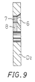
- the front surface of the die part D2 is formed with a recess 7 which communicates with the tapered recess 6.
- the recess 7 communicates with the right half of the opening 4 through a guide recess 8 formed on the front surface of the die part D2.
- the front surface of the die part D2 is also formed with a groove 9 through which the sponge rubber R2 is to be supplied.
- the groove 9 communicates with the left half of the opening 4.
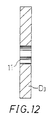
- the third part D3 is formed with an opening 11 which is configured to conform substantially to the outer configuration of the molding M to be formed.
- the die parts D1, D2, D3 are assembled in this order to form the molding die D, where the core member 10 is closely received with the opening 4 of the second die part D2 and is projected into the opening 11 of the third die part D3, thereby to form an annular extruding opening 11a which is configured to conform to the sectional configuration of the molding M.
- the molding die D is mounted on a head H of an extruder (not shown) to form the apparatus for manufacturing the molding M.
- the extruder includes a feed pipe 21 of the hard rubber R1 and a feed pipe 22 of the sponge rubber R2.
- the opening 1 of the first die part D1 and the opening 5 of the second die part D2 cooperate to form a first flow conduit C1 which communicates with the feed pipe 21 to permit the hard rubber R1 to flow toward the extruding opening 11a.
- the groove 9 communicates with the feed pipe 22 and acts as a second flow conduit C2 for flowing the sponge rubber R2 toward the extruding opening 11a.
- the tapered recess 6, the recess 7 and the guide recess 8 of the second die part D2 cooperate to form a third flow conduit C3 which communicates with both of the feed pipes 21, 22 through the through holes 3, the groove 2 and the thin grooves 2a, respectively, to permit the hard and sponge rubber R1, R2 to flow toward the extruding opening 11a.
- the molding M is manufactured by the above-described apparatus.
- the hard rubber R1 and sponge rubber R2 are simultaneously fed from the feed pipe 21, 22 and are distributed over the flow conduits C1, C2, C3.
- a part of the hard rubber R1 fed from the feed pipe 21 is introduced into the first conduit C1 and is directly extruded from the extruding opening 11a to form the first portion M1 of the molding M.
- a part of the sponge rubber R2 fed from the feed pipe 22 is introduced into the second conduit C2 and is directly extruded from the extruding opening 11a to form the second portion M2 of the molding M.
- the remainder of the hard rubber R1 fed from the feed pipe 21 is introduced into the third conduit C3 through the through holes 3.
- the remainder of the sponge rubber R2 fed from the feed pipe 22 is introduced into the third conduit C3 through the groove 2 and the thin grooves 2a.
- the hard and sponge rubber R1, R2 introduced into the third conduit C3 are effectively combined and are subsequently extruded from the extruding opening 11a to form the third portions M3 of the molding M.
- the hard and sponge rubber R1, R2 are introduced into the tapered recess 6 in two rows of stick-like form and in three layers of strip-like form, respectively, as shown in FIG. 13a.
- the hard and sponge rubber R1, R2 are gradually compressed in the tapered recess 6 and are advanced to the recess 7 where the rubber R1, R2 are formed to hybrid R3, as shown in FIG. 13b.
- the hybrid R3 is extruded from the extruding opening 11a through the guide recess 8 to form the third portions M3 of the molding M where the sectional configuration of the hard rubber R1 of the hybrid R3 is deformed along imaginary arcuate surfaces 23a, 23b concentrical with the arcuate surface of the third portion M3, as shown in FIG. 13C.
- the molding M comprising the three portions M1, M2, M3 which are formed of three types of material R1, R2, R3, respectively, and which are integrally formed as a unit, is effectively formed in only one extruding process. Since the hard and sponge rubber R1, R2 are simultaneously fed from the feed pipes 21, 22, the three portions M1, M2, M3 are fixedly bonded to one another and the hard and sponge rubber R1, R2 of the hybrid R3 are also fixedly bonded to each other.
- the preferred embodiment herein described can be modified, if required.
- the configuration, the arrangement and the number of the thin grooves 2a and the through holes 3 can be modified to change the properties of the hybrid R3.
- a weather strip of an automobile can be easily formed.
- a weather strip S of an automobile mainly comprises an engagement member 33 which is to be mounted on an automobile body 36 and a tubular sealing member 34 which is to be contacted to an automobile door 37 when the door 37 is closed.
- These members 33 and 34 are formed of hard rubber and sponge rubber, respectively, and are integrally formed as a unit.
- the weather strip S generally includes a lip member 31 of which the lower surface is to be received with one end 32a of an interior decoration member 32.
- the lip member 31 is integrally formed to the engagement member 33.
- the lip member 31 is formed of hybrid of the hard rubber and the sponge rubber.
- the numeral 35 shows an ornamental covering member having a color identical with that of the interior decoration member 32.
Landscapes
- Engineering & Computer Science (AREA)
- Mechanical Engineering (AREA)
- Manufacturing & Machinery (AREA)
- Seal Device For Vehicle (AREA)
- Extrusion Moulding Of Plastics Or The Like (AREA)
- Vehicle Waterproofing, Decoration, And Sanitation Devices (AREA)
- Molding Of Porous Articles (AREA)
Claims (8)
- Bande d'étanchéité moulée (M, S) comprenant une partie (M1) constituée en caoutchouc plus dur (R1), une partie (M2) constituée en caoutchouc plus souple (R2) et une partie hybride (M3) constituée d'un mélange hybride des deux caoutchoucs (R1, R2).
- Procédé de fabrication d'une bande d'étanchéité moulée, la bande d'étanchéité (M, S) comprenant une partie (M1) constituée d'un caoutchouc plus dur (R1), une partie (M2) constituée en caoutchouc plus souple (R2) et une partie hybride (M3) constituée d'un mélange hybride des deux caoutchoucs (R1, R2), le procédé comprenant les étapes suivantes :
préparer une matrice de moulage (D) ayant une ouverture d'extrusion (11) et au moins trois conduites d'écoulement (C1, C2, C3) en communication avec ladite ouverture d'extrusion ;
amener simultanément des compositions pour constituer les matériaux plus durs et plus souples (R1, R2) dans ladite matrice de moulage (D) ;
introduire une partie de la composition pour former le caoutchouc plus dur (R1) dans la première conduite d'écoulement (C1) de ladite matrice de moulage et l'extruder pour former la partie (M1) constituée en caoutchouc plus dur ;
introduire une partie de la composition pour constituer le caoutchouc plus souple (R2) dans la seconde conduite d'écoulement (C2) de ladite matrice de moulage et l'extruder pour former la partie (M2) constituée de caoutchouc plus souple ; et
introduire le reste des deux compositions (R1, R2) dans la troisième conduite (C3) de ladite matrice de moulage pour former un mélange hybride des deux caoutchoucs (R1, R2) et extruder le mélange par ladite ouverture d'extrusion (11) pour former la partie hybride (M3). - Procédé selon la revendication 2, dans lequel la partie hybride (M3) est un matériau en couche dans lequel le caoutchouc plus dur (R1) est pris en sandwich entre des couches de caoutchouc plus souple (R2).
- Procédé selon la revendication 2 ou 3, comprenant en outre l'opération de compression du matériau hybride avant d'extruder la partie hybride (M3) par ladite ouverture d'extrusion (11).
- Appareil de fabrication d'une bande d'étanchéité moulée pour fabriquer une bande d'étanchéité moulée (M, S) comprenant des parties en trois caoutchoucs de dureté différentes, l'appareil comprenant :
un premier tube d'amenée (21) pour amener une composition destinée à former un caoutchouc plus dur (121) ;
un second tube d'amenée (22) pour amener une composition devant former un caoutchouc plus souple (R2) ; et
une matrice de moulage (D) comportant une ouverture d'extrusion (11) et au moins trois conduites d'écoulement (C1, C2, C3) communiquant avec ladite ouverture d'extrusion, la première conduite d'écoulement (C1) communiquant avec ledit premier tube d' amenée (21), la seconde conduite d'écoulement (C2) communiquant avec ledit second tube d'amenée (22) et la troisième conduite d'écoulement (C3) communiquant à la fois avec lesdits premier et second tubes d'amenée (21, 22), de façon à former un mélange hybride des deux compositions dans ladite troisième conduite d'écoulement (C3) lorsque les deux compositions arrivent par lesdits premier et second tubes d'amenée (21, 22). - Appareil selon la revendication 5, dans lequel ladite troisième conduite d'écoulement (C3) communique avec à la fois lesdits premier et second tubes d'amenée (21, 22) par l'intermédiaire d'une pluralité de premiers orifices (3) et une pluralité de seconds orifices (2a) formés sur ladite matrice de moulage (D), respectivement et dans lequel lesdits premiers orifices (3) sont classés entre lesdits seconds orifices (2a) de façon que le mélange hybride forme un matériau dans lequel le caoutchouc plus dur (R1) est réparti dans le caoutchouc plus souple (R2).
- Appareil selon la revendication 6, dans lequel lesdits seconds orifices (2a) sont trois orifices allongés fins et dans lequel lesdits premiers orifices (3) sont classés entre lesdits seconds orifices (2a) et sont constitués par une pluralité de petits trous traversants disposés en série, de façon que le mélange hybride constitue un matériau en couche dans lequel le caoutchouc plus dur (R1) est pris en sandwich entre des couches de caoutchouc plus souple (R2).
- Bande d'étanchéité moulée (M, S) produite par l'appareil selon l'une quelconque des revendications 5 à 7.
Applications Claiming Priority (2)
| Application Number | Priority Date | Filing Date | Title |
|---|---|---|---|
| JP2119475A JP2931036B2 (ja) | 1990-05-09 | 1990-05-09 | シール材、並びにその成形方法及び装置 |
| JP119475/90 | 1990-05-09 |
Publications (3)
| Publication Number | Publication Date |
|---|---|
| EP0456483A2 EP0456483A2 (fr) | 1991-11-13 |
| EP0456483A3 EP0456483A3 (en) | 1992-03-25 |
| EP0456483B1 true EP0456483B1 (fr) | 1995-02-01 |
Family
ID=14762227
Family Applications (1)
| Application Number | Title | Priority Date | Filing Date |
|---|---|---|---|
| EP91304156A Expired - Lifetime EP0456483B1 (fr) | 1990-05-09 | 1991-05-09 | Bande d'étanchéité moulée et appareil et procédé pour sa fabrication |
Country Status (4)
| Country | Link |
|---|---|
| US (1) | US5124189A (fr) |
| EP (1) | EP0456483B1 (fr) |
| JP (1) | JP2931036B2 (fr) |
| DE (1) | DE69107114T2 (fr) |
Families Citing this family (5)
| Publication number | Priority date | Publication date | Assignee | Title |
|---|---|---|---|---|
| JPH0531785A (ja) * | 1991-07-30 | 1993-02-09 | Kinugawa Rubber Ind Co Ltd | ウエザーストリツプの製造方法 |
| US6237966B1 (en) * | 1998-07-02 | 2001-05-29 | Bidco Plastic Extrusion, Inc. | Co-extruded dual durometer hardness pipe gasket |
| JP3861606B2 (ja) * | 2001-02-21 | 2006-12-20 | 豊田合成株式会社 | 自動車用ウエザストリップ |
| JP2006304387A (ja) * | 2005-04-15 | 2006-11-02 | Yazaki Corp | シール部材及び該シール部材を備えたグロメット |
| CN102941662B (zh) * | 2012-11-23 | 2015-02-25 | 深圳市飞荣达科技股份有限公司 | 一种多腔复合橡胶条挤出模具 |
Family Cites Families (6)
| Publication number | Priority date | Publication date | Assignee | Title |
|---|---|---|---|---|
| IE32760B1 (en) * | 1967-12-28 | 1973-11-28 | Rasmussen O B | Extruded sheet materials suitable for textile purposes |
| DE3229554C1 (de) * | 1982-08-07 | 1984-03-15 | Hoechst Ag, 6230 Frankfurt | Verfahren und Vorrichtung zur Herstellung coextrudierter mehrschichtiger Verbundfolien aus thermoplastischen Kunststoffen |
| FR2584975B1 (fr) * | 1985-07-19 | 1987-11-20 | Hutchinson | Procede d'obtention par co-extrusion de profiles comprenant au moins deux parties ayant des proprietes differentes et profiles ainsi obtenus |
| US4898760A (en) * | 1987-11-17 | 1990-02-06 | Amesbury Industries, Inc. | Process and apparatus for extruding a low density elastomeric thermoplastic foam |
| US5013379A (en) * | 1988-01-25 | 1991-05-07 | Gencorp Inc. | Cohesive bonding process for forming a laminate of a wear resistant thermoplastic and a weather resistant rubber |
| DE68916311T2 (de) * | 1988-04-12 | 1994-12-15 | Jsp Corp | Verfahren zur Herstellung einer thermoplastischen Kunststoffolie und deren Verwendung als Puffermaterial. |
-
1990
- 1990-05-09 JP JP2119475A patent/JP2931036B2/ja not_active Expired - Lifetime
-
1991
- 1991-05-06 US US07/695,982 patent/US5124189A/en not_active Expired - Fee Related
- 1991-05-09 EP EP91304156A patent/EP0456483B1/fr not_active Expired - Lifetime
- 1991-05-09 DE DE69107114T patent/DE69107114T2/de not_active Expired - Fee Related
Also Published As
| Publication number | Publication date |
|---|---|
| JPH0416334A (ja) | 1992-01-21 |
| US5124189A (en) | 1992-06-23 |
| DE69107114D1 (de) | 1995-03-16 |
| EP0456483A2 (fr) | 1991-11-13 |
| EP0456483A3 (en) | 1992-03-25 |
| DE69107114T2 (de) | 1995-08-03 |
| JP2931036B2 (ja) | 1999-08-09 |
Similar Documents
| Publication | Publication Date | Title |
|---|---|---|
| FI69007B (fi) | Kompositmaterial av aotminstone ett ytterskikt av polyvinylidenfluorid och foerfarande foer framstaellning av detsamma | |
| US5781963A (en) | Coextruded screwdriver handle and method of making same | |
| US5087488A (en) | Method and apparatus for forming a plastic article with an overlay of varying thickness having a shaded color appearance | |
| GB1380255A (en) | Decorative trim strips | |
| CA2006675C (fr) | Methode et moule de fabrication d'un article moule multicouche | |
| EP0528560A1 (fr) | Dispositif combiné de tête d'extrusion pour fabriquer un joint d'étanchéité | |
| EP0456483B1 (fr) | Bande d'étanchéité moulée et appareil et procédé pour sa fabrication | |
| US5250248A (en) | Apparatus and process for manufacturing a molding | |
| EP1153799A1 (fr) | Objet moule, et procede et dispositif de fabrication dudit objet moule | |
| JPH0313059B2 (fr) | ||
| US6103167A (en) | Process for producing a sandwich molded article | |
| US20020031568A1 (en) | Metal mold for producing a synthetic resin molded product in a compression-molding method | |
| JP2500681B2 (ja) | 自動車用装飾モ―ルの製造方法 | |
| JP3169478B2 (ja) | 被覆用シートおよびその製造方法 | |
| JP3507017B2 (ja) | ベルトモールの製造方法 | |
| JPH0768623A (ja) | 被覆用シートの製造方法 | |
| JP2554598B2 (ja) | 合成樹脂製ブロー成形管 | |
| JP3343955B2 (ja) | 芯金入りトリムの押出方法 | |
| JPS58108122A (ja) | ウエザ−ストリツプの製造方法 | |
| CN217777734U (zh) | 一种冰箱密封条挤出模具 | |
| JP3204806B2 (ja) | 成形品の製造方法 | |
| JPS5448861A (en) | Multiple simultaneous extrusion coater | |
| JPH01204713A (ja) | モールディングの製造方法 | |
| JP3860490B2 (ja) | 接着層を有するフッ素樹脂フィルムの成形方法及びそのフッ素樹脂フィルム | |
| JPH01221218A (ja) | モールディングの製造方法 |
Legal Events
| Date | Code | Title | Description |
|---|---|---|---|
| PUAI | Public reference made under article 153(3) epc to a published international application that has entered the european phase |
Free format text: ORIGINAL CODE: 0009012 |
|
| AK | Designated contracting states |
Kind code of ref document: A2 Designated state(s): DE FR GB |
|
| PUAL | Search report despatched |
Free format text: ORIGINAL CODE: 0009013 |
|
| AK | Designated contracting states |
Kind code of ref document: A3 Designated state(s): DE FR GB |
|
| 17P | Request for examination filed |
Effective date: 19920514 |
|
| 17Q | First examination report despatched |
Effective date: 19931014 |
|
| GRAA | (expected) grant |
Free format text: ORIGINAL CODE: 0009210 |
|
| AK | Designated contracting states |
Kind code of ref document: B1 Designated state(s): DE FR GB |
|
| REF | Corresponds to: |
Ref document number: 69107114 Country of ref document: DE Date of ref document: 19950316 |
|
| ET | Fr: translation filed | ||
| PLBE | No opposition filed within time limit |
Free format text: ORIGINAL CODE: 0009261 |
|
| STAA | Information on the status of an ep patent application or granted ep patent |
Free format text: STATUS: NO OPPOSITION FILED WITHIN TIME LIMIT |
|
| 26N | No opposition filed | ||
| PGFP | Annual fee paid to national office [announced via postgrant information from national office to epo] |
Ref country code: DE Payment date: 19990507 Year of fee payment: 9 |
|
| PGFP | Annual fee paid to national office [announced via postgrant information from national office to epo] |
Ref country code: FR Payment date: 19990511 Year of fee payment: 9 |
|
| PGFP | Annual fee paid to national office [announced via postgrant information from national office to epo] |
Ref country code: GB Payment date: 19990512 Year of fee payment: 9 |
|
| PG25 | Lapsed in a contracting state [announced via postgrant information from national office to epo] |
Ref country code: GB Free format text: LAPSE BECAUSE OF NON-PAYMENT OF DUE FEES Effective date: 20000509 |
|
| GBPC | Gb: european patent ceased through non-payment of renewal fee |
Effective date: 20000509 |
|
| PG25 | Lapsed in a contracting state [announced via postgrant information from national office to epo] |
Ref country code: FR Free format text: LAPSE BECAUSE OF NON-PAYMENT OF DUE FEES Effective date: 20010131 |
|
| PG25 | Lapsed in a contracting state [announced via postgrant information from national office to epo] |
Ref country code: DE Free format text: LAPSE BECAUSE OF NON-PAYMENT OF DUE FEES Effective date: 20010301 |
|
| REG | Reference to a national code |
Ref country code: FR Ref legal event code: ST |