EP0456054B1 - Wolframwenteln mit niedriger Durchbiegung und ihre Anwendung bei Lampen - Google Patents
Wolframwenteln mit niedriger Durchbiegung und ihre Anwendung bei Lampen Download PDFInfo
- Publication number
- EP0456054B1 EP0456054B1 EP91106807A EP91106807A EP0456054B1 EP 0456054 B1 EP0456054 B1 EP 0456054B1 EP 91106807 A EP91106807 A EP 91106807A EP 91106807 A EP91106807 A EP 91106807A EP 0456054 B1 EP0456054 B1 EP 0456054B1
- Authority
- EP
- European Patent Office
- Prior art keywords
- filament
- tungsten
- lamp
- grain
- gar
- Prior art date
- Legal status (The legal status is an assumption and is not a legal conclusion. Google has not performed a legal analysis and makes no representation as to the accuracy of the status listed.)
- Expired - Lifetime
Links
Images


Classifications
-
- H—ELECTRICITY
- H01—ELECTRIC ELEMENTS
- H01K—ELECTRIC INCANDESCENT LAMPS
- H01K1/00—Details
- H01K1/02—Incandescent bodies
- H01K1/04—Incandescent bodies characterised by the material thereof
- H01K1/08—Metallic bodies
Definitions
- This invention relates to an improved, sag resistant tungsten filament and its use in lamps. More particularly, this invention relates to a tungsten filament being at least about 85% recrystallized and having a microstructure comprising a large, elongated and interlocking grain structure, a method for producing same and its use in electric lamps.
- tungsten filaments in electric lamps such as incandescent lamps
- the efficiency or efficacy as well as the light output and color rendering ability of an incandescent lamp is very much dependent on the temperature at which the filament operates.
- the filament temperature also determines the quality of the emitted light.
- the more efficient incandescent lamps such as tungsten-halogen lamps, employ filaments in the form of coils or helixes and more Particularly coiled-coils or double helixes in which the filaments are operated at temperatures of about 2500°C. In stage and studio lamps the filaments are operated at temperatures as high as 2900°C.
- Tungsten ingots intended for making tungsten filaments contain a very minor amount of dopants such as potassium, aluminum and silicon.
- tungsten ingots used to produce wire from which filaments are made consist essentially of from about 99.95 to about 99.99 wt. % of tungsten, along with minor amounts of one or more dopants and impurities.
- GB-A-1053020 the filament wire, made of tungsten containing grain growth promoting additives, was alloyed with rhenum.
- Such a fibrous microstructure results in a relatively weak filament having extremely little, if any, sag resistance at the 2000°C plus temperatures at which filaments are operated. Accordingly, those skilled in the art know that such filaments have to be recrystallized such as is disclosed, for example, by Smithells on pages 136-145 and in U.S. Patent Nos. 3,927,989 and 4,296,352. Both of these patents disclose that tungsten wire filaments normally recrystallize at a temperature in the general range of between about 1900-2500°C. The most ideal filament would be one formed of a single crystal of tungsten or one that was recrystallized in a manner so as to form a single crystal of tungsten.
- Such a filament would have the maximum possible sag resistance and tensile strength.
- the present invention seeks to provide a coiled tungsten filament having enhanced sag resistance.
- GSP Grain Shape Parameter
- GBF Grain Boundary Factor
- the filament has a GAR of at least 50 and more preferably at least about 100.
- the filament has a grain shape parameter (GSP) having a value of at least about 10 and preferably at least about 15.
- GSP grain shape parameter
- the value of the grain shape parameter is equal to the value of the grain aspect ratio (GAR) divided by the value of the grain boundary factor (GBF).
- GBF grain boundary factor
- the GBF and a method for obtaining same is set forth under DETAILED DESCRIPTION below, but basically it relates to the interlocking nature of the boundary of adjacent tungsten crystals or grains in a filament, with relatively straight grain boundaries transverse to the longitudinal axis of the wire being the poorest and resulting in the greatest amount of sag (as Smithells also shows on pages 136 and 137 of his book).
- the GAR or grain aspect ratio is the average grain or crystal length to diameter ratio.
- the GSP or grain shape parameter is a figure of merit which combines the properties of the other two parameters.
- large numerical values for GAR and GSP are desirable, whereas smaller values are preferred in the GBF.
- the GSP will preferably have a value of at least about 10 and preferably at least about 15.
- the GAR will have a value of at least about 50 and preferably at least about 100 and the GBF will preferably have a value less than about 15 and preferably less than about 8.
- the filament of this invention will be at least about 85% recrystallized and preferably at least about 95% recrystallized and may be used at temperatures above 2300°C with little or no sag.
- the filaments of this invention may be uncoiled wire, single coil, double and even triple coils, as well as tungsten ribbon.
- the present invention also relates to lamps containing tungsten filaments having the microstructure of the present invention.
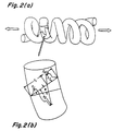
- Figures 1 and 2 schematically illustrate a portion of a filament according to the present invention illustrating interlocking grains and steps employed in obtaining the GBF.
- Figure 3 is a time-temperature graph of a single anneal process used to anneal filaments and obtain the grain structure according to the invention.
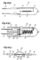
- Figure 4 schematically illustrates single and double ended incandescent lamps each having a filament according to the present invention.
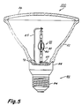
- Figure 5 schematically illustrates a combination double ended tungsten halogen lamp having a filament of the present invention, IR filter and a parabolic reflector.
- the present invention relates to a tungsten filament having a microstructure which comprises a large, elongated and interlocking grain structure which is defined by a grain shape parameter (GSP) having a value of at least about 10, wherein the GSP is equal to the value of the grain aspect ratio (GAR) divided by the value of the grain boundary factor (GBF).
- GSP grain shape parameter
- GAR grain aspect ratio
- GPF grain boundary factor
- a filament may be thermally etched in-situ in a lamp by energizing the lamp at its rated voltage for at least about fifty (50) hours. After the filaments or wires have been etched, they are then placed in a field emission scanning electron microscope, such as a Hitachi S-800 field emission scanning electron microscope (SEM) which has a resolution capability of about 2 X 10 ⁇ 11m (20 ⁇ ) and a depth of field of 100»m at 1000X magnification,
- SEM field emission scanning electron microscope
- Figure 1 schematically represents such an image taken as a section of a schematically depicted coil section of a filament shown in Figure 2(a).
- Figure 1 also illustrates the step-by-step procedures taken in the grain shape analyses. The measurements are straightforward and can be made directly on the viewing screen (CRT) of an SEM or on photographs taken by the SEM.
- the first step is to find one end of a grain boundary A, then another end of the same grain boundary C, and one edge B of the wire. It is axiomatic, of course, that the diameter of the grain or tungsten crystal is substantially the same as the diameter of the wire or filament.
- a line AB is drawn which defines the one edge of the wire and another line is drawn normal to AB as shown in Figure 1(c), D being the edge of the other side of the wire and line AD defining the diameter of the wire.
- Line AC is then drawn in that portion of the grain boundary which crosses AC and the maximums and minimums marked with X's as shown in Figure 1(d).
- the angle, ⁇ , of a grain boundary is determined as shown in Figures 1 and 2 as the angle between AC and AD.
- the wave length, ⁇ is the reciprocal of the number of waves (boundary undulations) across the diameter of the filament wire.
- Height, h, or amplitude of a wave is determined as shown in Figure 2 by reference to the line AC ( Figure 1) connecting the ends of the boundary. In some cases it has been found convenient to measure peak to peak amplitudes and divide by two. Both ⁇ and h are averaged and expressed as fractions of the wire diameter.
- the length of a primary turn divided by the wire diameter is k and is constant for a given filament design.
- Grain Aspect Ratio the average grain length to diameter ratio. This is a familiar, as well as convenient parameter, since it is so frequently associated with high temperature creep performance.
- Grain Aspect Ratio is essentially the reciprocal of the number of grain boundaries multiplied by the length evaluated and divided by the wire diameter. The higher the Grain Aspect Ratio, the fewer sliding boundaries can contribute to filament creep and the stronger is the filament.
- Tungsten filaments having the properties according to this invention have been produced by two different processes.
- One process is a continuous heating process, whereas the other process is a two-stage, discontinuous heating process with cooling to room temperature between each heating stage. In either case the process starts with a coiled filament or filament coil having essentially 0% recrystallization.
- the tungsten wire develops a fibrous microstructure which remains essentially unchanged during the subsequent forming of the filament.
- the fibrous microstructure results in very ductile tungsten, but at the high temperatures of 2300°C or more at which filaments are heated in lamps in order to produce light, this fibrous structure rapidly recrystallizes resulting in sagging and breaking of the filament.
- tungsten filament wire is first wound around a molybdenum, steel or other wire mandrel, called a primary mandrel, to form a coiled structure.
- a primary mandrel a molybdenum, steel or other wire mandrel
- a single coil type of filament is used in many types of incandescent lamps.
- the tungsten filament is in the form of a double coil or a coiled-coil.
- the tungsten filament wire is first wound around a primary mandrel to form the first coil, with the so-formed coil structure then wound around a secondary mandrel to form the secondary coil.
- the filament After the filament has been completely formed and annealed to minimize elastic springback after subsequent mandrel dissolve, it is removed from the secondary mandrel and placed in an acid bath containing acid such as a mixture of nitric and sulphuric acids and water which is well known to those skilled in the art and is disclosed, for example, in U.S. Patent 4,440,729. This is done to dissolve away the primary (and secondary) mandrel to yield the final filament.
- acid bath containing acid such as a mixture of nitric and sulphuric acids and water which is well known to those skilled in the art and is disclosed, for example, in U.S. Patent 4,440,729. This is done to dissolve away the primary (and secondary) mandrel to yield the final filament.
- a coiled-coil filament is processed with a recrystallization time-temperature schedule consisting of about 30 seconds with about 2650°K maximum temperature, followed by rapid cooling to room temperature.
- a typical recrystallization schedule for 60W, 120V filaments is shown in Figure 3 and has been successfully employed with this method to produce coiled-coil filaments suitable for 60W, 120V, miniature lamps having the properties of this invention.
- the specific time-temperature curve in Figure 3 is representative of typical recrystallization processes which achieve 85% minimum recrystallization, but does not exclude other time-temperature treatments such as shorter times with higher maximum temperatures or longer times with lower maximum temperatures.
- a preferred method for heating the filament employs a tungsten mandrel inside the center of the filament which is heated by passing electrical current through it, thereby indirectly heating the filament.
- a tungsten mandrel is placed inside the center of the filament and attached to electrodes which are then energized to heat the mandrel with filament.
- the tungsten mandrel is slightly smaller than the secondary mandrel used to form the coiled-coil, typically 2.54mm (1.0 mil) smaller in diameter than the secondary mandrel.
- the heating is performed in a reducing atmosphere, such as forming gas consisting of 90% nitrogen and 10% hydrogen.
- Filament distortion such as non-uniform secondary pitch or the spacing between adjacent secondary turns, is minimized if the molybdenum primary mandrel is present in the coiled-coil filament during the recrystallization heating treatment.
- a preferred process for the continuous annealing recrystallization method starts with a conventionally-processed coiled-coil, including first coiling on a molybdenum primary mandrel, annealing, second coiling and annealing, but not including acid dissolving of the primary mandrel. After recrystallizing the filament on a tungsten mandrel heated with electric current to produce the filament time-temperature curve in Figure 3, the molybdenum primary mandrel is then dissolved with the standard acid process.
- the recrystallization heating schedule such as shown in Figure 3 could be performed by any other method to achieve the specified time-temperature treatment, such as placing the filament in a small tungsten boat and using a rapid-response furnace or attaching lead wires to the filament and directly heating the filament with an applied electrical current.
- the amount of recrystallization was determined by a coil stretch test which measures the difference in the springback properties of the tungsten. These properties are controlled by the elastic-plastic stress-strain behavior changes (such as yield strength and strain hardening rate) and is reflected in different springback properties.
- the coil stretch test consists basically of pulling the coil axially to a fixed stretch length of about 8 times the original length, releasing the tension and measuring the relaxed length. The percent recrystallization can then be calculated from the relaxed length resulting after stretching and two reference relaxed lengths, one for 0% recrystallization and one for 100% recrystallization. The reference coils are stretched to the same fixed stretch length.
- the 0% recrystallized reference filament has been processed through standard coiling treatments (first coiling, annealing, second coiling, annealing and acid dissolving of mandrel), but has not been heated in any subsequent recrystallization treatments.
- the 100% recrystallized reference filament has been processed with a high temperature treatment to assure 100% recrystallization. For a fixed treatment time, the temperature is high enough to define a 100% recrystallized reference when filaments processed to successively higher temperatures produce no significant increase in the relaxed length after stretch testing. Stretch tests are performed after recrystallization and subsequent mandrel dissolving. Typically the relaxed length increases less than 0.02% per K increase in temperature for recrystallization treatments defined as 100% recrystallized.
- percent recrystallization 100 (l-l o )/(l l -l o ) where l is the relaxed length of the filament after stretching to a constant stretch length, l o is the relaxed length of the 0% recrystallized reference filament after stretching to the same constant stretch length and l1 is the relaxed length of the 100% recrystallized reference filament after stretching to the same constant stretch length.
- the correlation between the stretch test and the conventional tedious metallographic procedure employing many polished and etched sections is good. This coil stretch test method has been published by Pugh and McWhorter as "An Elastic Recovery Test for Recrystallization," Metall. Trans. vol. 20A, p. 1885-1887 (Sept. 1989).
- the unrecrystallized filaments were heated in a forming gas atmosphere to a temperature broadly ranging between 1250-2050°C and preferably 1650-2050°C for about 7 minutes for the first stage.
- the molybdenum primary mandrel was dissolved away prior to the first stage anneal and heating was accomplished by resistive heating with lead wires attached to the filaments.
- This first stage annealing resulted in from about 5 to 73% recrystallization, depending on the temperature, with the higher temperatures being preferred.
- the partially recrystallized filaments were briefly cooled to room temperature and then rapidly heated again using a conventional pulsed resistive heating or flashing technique pulsing temperatures starting at 2200°K up to 3200°K over a period of about twenty seconds.
- Double coiled filaments made with this method for 45 watt (120V) tungsten halogen lamps exhibited essentially about 100% recrystallization and virtually no sag when the first anneal was accomplished in the 1650-2050°C range.
- These filaments were coiled-coil filaments about 12 mm long from 0.06 mm diameter wire doped with potassium (GE 218 grade).
- Filaments have been made in this manner having a GSP of 86, a GBF of 4.4 and a GAR of 289. Filaments having similar properties according to the invention have also been made by heating in tungsten boats in a conventional furnace in a forming gas atmosphere.
- filaments of similar construction taken from competitive tungsten halogen lamps made by another manufacturer exhibited a GAR of from about 12 to 22 and a GSP of from about 0.5 to 4.3.
- filaments made according to this invention were made from a standard grade of tungsten filament wire made and available from GE Lighting located at Tungsten Road in Cleveland, Ohio, and designated as their GE Type 218 wire. This wire has a purity of 99.95+ % W and is doped with potassium ranging from 65-80 ppm. Filaments having characteristics according to this invention have also been made from tungsten filament wire obtained from competitive wire manufacturers, both in the U.S. and Japan.
- FIG. 4 schematically illustrates various types of lamps containing filaments according to the present invention.
- lamp 10 has a tubular envelope made of a suitable light transmissive vitreous envelope 12 formed from a high temperature aluminosilicate glass which may be of the type disclosed and claimed in U.S. Patent 4,737,685 the disclosures of which are incorporated herein by reference.
- a coiled-coil tungsten filament 13 having properties according to the present invention is connected to and supported within said vitreous envelope by inlead wires 14 and 16 made of molybdenum and which extend through a customary pinch seal 18.
- molybdenum inleads 14 and 16 can be connected by means of welding, brazing or other suitable means to less costly metals of a greater or the same diameter to provide electrical connection for the filament and support for the lamp.
- Envelope 12 may also contain a fill comprising a mixture of nitrogen, hydrogen, noble gas, phosphorus, and a hydrogen such as chlorine and bromine.
- FIG. 4(b) illustrates another type of lamp useful in the practice of this invention wherein molybdenum foil is used to effect a hermetic seal in the pinch seal area, as is the practice with such lamps having quartz envelopes.
- lamp 20 comprises quartz envelope 22 containing two pinch-sealed inlead constructions comprising outer terminal leads 32 and 32′ and inner terminal leads 26 and 26′ connected to opposite ends of intermediate molybdenum sealing foils 28 and 28′, respectively.
- a compact coiled-coil tungsten filament 24 made according to the invention is attached at one end to inner lead 26 and at the other end to inner lead 26′.
- the leads are connected to the molybdenum sealing foils by suitable means, such as welding.
- Leads 26 and 26′ are made of molybdenum.
- Envelope 22 also contains a fill comprising a mixture of noble gas, hydrogen, a getter such as phosphorus, and a halogen such as chlorine, bromine and optionally, nitrogen.
- Figure 4(c) illustrates a double-ended miniature lamp 50 comprising a light transmissive, fused silica (quartz) envelope portion 40 containing a coiled-coil tungsten filament 60 according to the present invention welded at each end to filament spuds 62 and 62′ wherein both tubular end portions 54 and 54′ have been shrink sealed over foil members 64 and 64′ to form a hermetic seal and then cut to reduce their length to that desired.
- Outer leads 56 and 56′ extend past the end of tube portions 54 and 54′ which are cut to the desired length after assembly of the lamp. Shrink seals are preferred because deformation and misalignment of the tube portions of the lamp envelope are minimal as compared with that which can occur with pinch sealing.
- Shrink seals are known to those skilled in the art and examples of how to obtain same are found, for example, in U.S. Patents 4,389,201 and 4,810,932. Lamps of this construction are commercially available and are disclosed, for example, in EP-A-0397422.
- Lamp 50 is shown assembled into a parabolic reflector 61 illustrated in Figure 5.
- combination 100 contains lamp 50 mounted into the bottom portion of parabolic glass reflector 61 by means of conductive mounting legs 65 and 67 which project through seals (not shown) at the bottom portion 72 of glass reflector 61.
- Lamp base 80 is crimped onto the bottom portion of the glass reflector by means not shown at neck portion 82.
- Screw base 84 is a standard screw base for screwing the completed assembly 60 into a suitable socket.
- Glass or plastic lens or cover 86 is attached or hermetically sealed by adhesive or other suitable means to the other end of reflector 61 to complete the lamp assembly.
- Lamp 50 is also shown having coating 90 on the exterior surface of the lamp envelope for selectively reflecting infrared energy emitted by the filament back to the filament wherein at least a portion of the infrared radiation is converted to visible light.
- the coating 50 is preferably made up of alternating layers of a low refractory index material such as silica and a high refractory index material such as tantala, titania, niobia and the like for selectively reflecting and transmitting different portions of the electromagnetic spectrum emitted by the filament.
- the filter will reflect infrared radiation back to the filament and transmit the visible portion of the spectrum.
- Such filters and their use as coatings for lamps may be found, for example, in U.S. Patents 4,229,066 and 4,587,923.
Landscapes
- Resistance Heating (AREA)
- Optical Filters (AREA)
- Discharge Lamp (AREA)
Claims (14)
- Wolfram-Leuchtdrahtwendel mit einem langgestreckten und ineinandergreifenden Korngefüge, das mindestens etwa 85% rekristallisiert ist und einen Korngestalt-Parameter (GSP) von mindestens etwa 10 hat, wobei der GSP als Kornlängen-Verhältnis (GAR), dividiert durch den Korngrenzen-Faktor (GBF)

- Wolfram-Leuchtdrahtwendel nach Anspruch 1 mit einem GAR von mindestens 50.
- Leuchtdraht nach Anspruch 1, worin das GAR mindestens etwa 100 beträgt.
- Leuchtdraht nach Anspruch 3, der mindestens etwa 95% rekristallisiert ist.
- Leuchtdraht nach Anspruch 4, worin das GAR mindestens etwa 200 beträgt.
- Leuchtdraht nach Anspruch 5, enthaltend von etwa 500-3.000 ppm Molybdän, vorzugsweise von 1.000-2.500 ppm Molybdän.
- Leuchtdraht nach einem der Ansprüche 2 bis 6 mit einem GBF von weniger als etwa 15.
- Leuchtdraht nach Anspruch 7 mit einem GSP von mindestens etwa 15.
- Leuchtdraht nach Anspruch 8 mit einem GBF von weniger als etwa 8.
- Elektrische Glühlampe (10,20), umfassend einen hermetisch abgedichteten, lichtdurchlässigen Kolben (12,22), der den Leuchtdraht (13,24) nach einem der Ansprüche 1 bis 9 einschließt.
- Wolfram-Halogen-Lampe (50), umfassend einen hermetisch abgedichteten, lichtdurchlässigen Glaskolben (40), der ein oder mehrere Metallhalogenide und den Leuchtdraht (60) nach einem der Ansprüche 1 bis 9 einschließt.
- Lampe (50) nach Anspruch 10 oder 11, weiter enthaltend einen optischen Dünnfilm-Interferenzüberzug (90) auf der äußeren Oberfläche, um verschiedene Teile des Lichtspektrums selektiv zu reflektieren und durchzulassen.
- Lampe (50) nach Anspruch 12, worin der Überzug (90) IR-Strahlung zurück zum Leuchtdraht reflektiert, sichtbare Lichtstrahlung aber durchläßt.
- Wolfram-Halogen-Lampe (100), die innerhalb eines parabolförmigen Reflektors (61) montiert ist, wobei das optische Zentrum der Lampe (100) nahe dem optischen Zentrum des Reflektors (61) liegt, die Lampe (100) einen hermetisch abgedichteten, lichtdurchlässigen Glaskolben aufweist, der ein oder mehrere Metallhalogenide und einen Wolfram-Leuchtdraht (60) gemäß einem der Ansprüche 1 bis 9 enthält.
Applications Claiming Priority (2)
| Application Number | Priority Date | Filing Date | Title |
|---|---|---|---|
| US07/521,201 US5072147A (en) | 1990-05-09 | 1990-05-09 | Low sag tungsten filament having an elongated lead interlocking grain structure and its use in lamps |
| US521201 | 1990-05-09 |
Publications (3)
| Publication Number | Publication Date |
|---|---|
| EP0456054A2 EP0456054A2 (de) | 1991-11-13 |
| EP0456054A3 EP0456054A3 (en) | 1992-09-02 |
| EP0456054B1 true EP0456054B1 (de) | 1995-12-20 |
Family
ID=24075797
Family Applications (1)
| Application Number | Title | Priority Date | Filing Date |
|---|---|---|---|
| EP91106807A Expired - Lifetime EP0456054B1 (de) | 1990-05-09 | 1991-04-26 | Wolframwenteln mit niedriger Durchbiegung und ihre Anwendung bei Lampen |
Country Status (6)
| Country | Link |
|---|---|
| US (1) | US5072147A (de) |
| EP (1) | EP0456054B1 (de) |
| JP (1) | JP2703672B2 (de) |
| CA (1) | CA2039785C (de) |
| DE (1) | DE69115554T2 (de) |
| HU (1) | HUT57472A (de) |
Families Citing this family (19)
| Publication number | Priority date | Publication date | Assignee | Title |
|---|---|---|---|---|
| HU216708B (hu) * | 1994-10-24 | 1999-08-30 | Ge Lighting Tungsram Rt. | Non-sag volfrámhuzal |
| DE19607355C2 (de) * | 1995-03-03 | 2001-10-18 | Patent Treuhand Ges Fuer Elektrische Gluehlampen Mbh | Verfahren zur Herstellung von Wolframdraht, Wolframdraht und Glühlampe mit einem solchen Wolframdraht |
| DE19607356C2 (de) * | 1995-03-03 | 2001-09-20 | Patent Treuhand Ges Fuer Elektrische Gluehlampen Mbh | Verfahren zur Erzeugung eines vibrations- und durchhangarmen Wolframdrahtes, Wolframdraht und Glühlampe mit einem solchen Wolframdraht |
| US5580290A (en) * | 1995-06-15 | 1996-12-03 | Osram Sylvania Inc. | Method for recrystallization of tungsten filaments for incandescent lamps |
| US5604321A (en) * | 1995-07-26 | 1997-02-18 | Osram Sylvania Inc. | Tungsten-lanthana alloy wire for a vibration resistant lamp filament |
| US6190466B1 (en) | 1997-01-15 | 2001-02-20 | General Electric Company | Non-sag tungsten wire |
| US6034473A (en) * | 1997-11-26 | 2000-03-07 | Wybron, Inc. | Lighting system and lamp with optimal filament placement |
| US6066019A (en) * | 1998-12-07 | 2000-05-23 | General Electric Company | Recrystallized cathode filament and recrystallization method |
| US6129890A (en) * | 1999-09-07 | 2000-10-10 | Osram Sylvania Inc. | Method of making non-sag tungsten wire |
| US6165412A (en) * | 1999-09-07 | 2000-12-26 | Osram Sylvania Inc. | Method of making non-sag tungsten wire for electric lamps |
| US6669523B1 (en) * | 2000-08-23 | 2003-12-30 | General Electric Company | Method of dimensionally stabilizing a tungsten filament |
| US6624577B2 (en) * | 2001-03-19 | 2003-09-23 | General Electric Company | Tungsten-rhenium filament and method for producing same |
| US6597107B1 (en) | 2002-01-11 | 2003-07-22 | General Electric Company | Tungsten-rhenium filament and method for producing same |
| US6958475B1 (en) | 2003-01-09 | 2005-10-25 | Colby Steven M | Electron source |
| EP1976022A3 (de) * | 2007-03-29 | 2008-12-03 | Applied Materials, Inc. | Verfahren und Vorrichtung zur Herstellung einer Antireflexionsschicht oder einer Passivierungsschicht für Solarzellen |
| RU2389823C1 (ru) * | 2008-10-20 | 2010-05-20 | Федеральное государственное образовательное учреждение высшего профессионального образования "Сибирский федеральный университет" | Способ получения вольфрамовой проволоки |
| US20100133972A1 (en) * | 2008-12-02 | 2010-06-03 | Ceferino Garcia | Connector |
| JP2014063667A (ja) * | 2012-09-21 | 2014-04-10 | Stanley Electric Co Ltd | 白熱電球 |
| CN105047523B (zh) * | 2015-06-15 | 2017-03-08 | 成都凯赛尔电子有限公司 | 一种灯丝定型的方法 |
Family Cites Families (13)
| Publication number | Priority date | Publication date | Assignee | Title |
|---|---|---|---|---|
| US3297989A (en) * | 1964-03-23 | 1967-01-10 | Ling Temco Vought Inc | Probability transform generator for image recognition |
| GB1053020A (en) * | 1964-07-08 | 1966-12-30 | Gen Electric | Improvements in tungsten-rhenium alloy filament lamps |
| JPS5324885B2 (de) * | 1972-11-08 | 1978-07-24 | ||
| JPS50100879A (de) * | 1974-01-12 | 1975-08-09 | ||
| US3975219A (en) * | 1975-09-02 | 1976-08-17 | United Technologies Corporation | Thermomechanical treatment for nickel base superalloys |
| US4012659A (en) * | 1975-12-31 | 1977-03-15 | Gte Sylvania Incorporated | Method of flashing tungsten filament |
| US4020383A (en) * | 1975-12-31 | 1977-04-26 | Gte Sylvania Incorporated | Method of pulsing incandescent lamp filaments |
| US4291444A (en) * | 1978-08-28 | 1981-09-29 | General Electric Company | Process of manufacturing a tungsten lamp filament |
| US4296352A (en) * | 1979-12-19 | 1981-10-20 | General Electric Company | Incandescent lamp |
| SE420108B (sv) * | 1980-09-12 | 1981-09-14 | Lumalampan Ab | Forfarande for kemisk, automatisk upplosning av molybdenkerntrad i wolframspiraler jemte anordning for genomforande av forfarande |
| JPS5782961A (en) * | 1980-11-13 | 1982-05-24 | Tokyo Shibaura Electric Co | Halogen bulb for copying machine |
| CA1254402A (en) * | 1985-03-13 | 1989-05-23 | Raymond C. Benn | Turbine blade superalloy iii |
| US4863527A (en) * | 1987-06-05 | 1989-09-05 | Gte Products Corporation | Process for producing doped tungsten wire with low strength and high ductility |
-
1990
- 1990-05-09 US US07/521,201 patent/US5072147A/en not_active Expired - Lifetime
-
1991
- 1991-04-04 CA CA002039785A patent/CA2039785C/en not_active Expired - Fee Related
- 1991-04-19 HU HU911300A patent/HUT57472A/hu unknown
- 1991-04-26 EP EP91106807A patent/EP0456054B1/de not_active Expired - Lifetime
- 1991-04-26 DE DE69115554T patent/DE69115554T2/de not_active Expired - Fee Related
- 1991-05-07 JP JP3130330A patent/JP2703672B2/ja not_active Expired - Lifetime
Also Published As
| Publication number | Publication date |
|---|---|
| HU911300D0 (en) | 1991-10-28 |
| HUT57472A (en) | 1991-11-28 |
| US5072147A (en) | 1991-12-10 |
| CA2039785C (en) | 2002-06-18 |
| JP2703672B2 (ja) | 1998-01-26 |
| EP0456054A2 (de) | 1991-11-13 |
| DE69115554T2 (de) | 1996-08-01 |
| JPH04249852A (ja) | 1992-09-04 |
| CA2039785A1 (en) | 1991-11-10 |
| DE69115554D1 (de) | 1996-02-01 |
| EP0456054A3 (en) | 1992-09-02 |
Similar Documents
| Publication | Publication Date | Title |
|---|---|---|
| EP0456054B1 (de) | Wolframwenteln mit niedriger Durchbiegung und ihre Anwendung bei Lampen | |
| US20080135139A1 (en) | High ductility, high hot tensile strength tungsten wire and method of manufacture | |
| US6784605B2 (en) | Halogen incandescent lamp and a lighting apparatus using the lamp | |
| KR960016763B1 (ko) | 몰리브덴 기본합금 및 그로부터 제조된 인입선 | |
| US6624577B2 (en) | Tungsten-rhenium filament and method for producing same | |
| EP1335410B1 (de) | Wolfram-Rhenium-Glühfaden und Verfahren zur Herstellung desselben | |
| EP0213927B1 (de) | Von Gleichstromquelle gespeiste Hochdruckmetalldampfentladungslampe | |
| EP0241912A2 (de) | Kompakter Doppelwendelglühdraht | |
| US4283653A (en) | High emissivity filament for energy conserving incandescent lamps with infrared radiation returning envelopes | |
| JPH076739A (ja) | 白熱灯 | |
| EP0708977B1 (de) | Hochdruckentladungslampe | |
| US4185219A (en) | Tubular incandescent lamp | |
| JP2000340184A (ja) | 白熱ランプ | |
| US4863527A (en) | Process for producing doped tungsten wire with low strength and high ductility | |
| JP3773023B2 (ja) | 高圧放電ランプおよび照明装置 | |
| JP2752873B2 (ja) | 放電ランプ装置用電極棒の製造方法 | |
| JP3285148B2 (ja) | ハロゲン電球 | |
| JP2001060451A (ja) | フィラメントが同軸配置された管状バルブを具える白熱ランプ | |
| US3682720A (en) | Manufacture of substantially non-sagging refractory metal wire | |
| EP0271859B1 (de) | Kompakte Doppelglühwendel mit Anwendung der Steigung für Biegungskontrolle | |
| JPS63164157A (ja) | 白熱電球の製造方法 | |
| JPS5961589A (ja) | ウエルズ用モリブデン線 | |
| JP3125642B2 (ja) | 一端封止型白熱電球 | |
| JPS58209856A (ja) | 高圧ナトリウムランプ用電極支持管 | |
| US20050218804A1 (en) | Halogen incandescent lamp for mains voltage |
Legal Events
| Date | Code | Title | Description |
|---|---|---|---|
| PUAI | Public reference made under article 153(3) epc to a published international application that has entered the european phase |
Free format text: ORIGINAL CODE: 0009012 |
|
| AK | Designated contracting states |
Kind code of ref document: A2 Designated state(s): DE GB NL |
|
| PUAL | Search report despatched |
Free format text: ORIGINAL CODE: 0009013 |
|
| AK | Designated contracting states |
Kind code of ref document: A3 Designated state(s): DE GB NL |
|
| 17P | Request for examination filed |
Effective date: 19930225 |
|
| 17Q | First examination report despatched |
Effective date: 19940719 |
|
| GRAA | (expected) grant |
Free format text: ORIGINAL CODE: 0009210 |
|
| AK | Designated contracting states |
Kind code of ref document: B1 Designated state(s): DE GB NL |
|
| REF | Corresponds to: |
Ref document number: 69115554 Country of ref document: DE Date of ref document: 19960201 |
|
| PLBE | No opposition filed within time limit |
Free format text: ORIGINAL CODE: 0009261 |
|
| STAA | Information on the status of an ep patent application or granted ep patent |
Free format text: STATUS: NO OPPOSITION FILED WITHIN TIME LIMIT |
|
| 26N | No opposition filed | ||
| REG | Reference to a national code |
Ref country code: GB Ref legal event code: IF02 |
|
| PGFP | Annual fee paid to national office [announced via postgrant information from national office to epo] |
Ref country code: NL Payment date: 20020329 Year of fee payment: 12 |
|
| PG25 | Lapsed in a contracting state [announced via postgrant information from national office to epo] |
Ref country code: NL Free format text: LAPSE BECAUSE OF NON-PAYMENT OF DUE FEES Effective date: 20031101 |
|
| NLV4 | Nl: lapsed or anulled due to non-payment of the annual fee |
Effective date: 20031101 |
|
| PGFP | Annual fee paid to national office [announced via postgrant information from national office to epo] |
Ref country code: DE Payment date: 20080602 Year of fee payment: 18 |
|
| PGFP | Annual fee paid to national office [announced via postgrant information from national office to epo] |
Ref country code: GB Payment date: 20080429 Year of fee payment: 18 |
|
| GBPC | Gb: european patent ceased through non-payment of renewal fee |
Effective date: 20090426 |
|
| PG25 | Lapsed in a contracting state [announced via postgrant information from national office to epo] |
Ref country code: DE Free format text: LAPSE BECAUSE OF NON-PAYMENT OF DUE FEES Effective date: 20091103 |
|
| PG25 | Lapsed in a contracting state [announced via postgrant information from national office to epo] |
Ref country code: GB Free format text: LAPSE BECAUSE OF NON-PAYMENT OF DUE FEES Effective date: 20090426 |