EP0455578B1 - Hybrider Einphasenmotor mit veränderlicher Reluktanz - Google Patents
Hybrider Einphasenmotor mit veränderlicher Reluktanz Download PDFInfo
- Publication number
- EP0455578B1 EP0455578B1 EP91630021A EP91630021A EP0455578B1 EP 0455578 B1 EP0455578 B1 EP 0455578B1 EP 91630021 A EP91630021 A EP 91630021A EP 91630021 A EP91630021 A EP 91630021A EP 0455578 B1 EP0455578 B1 EP 0455578B1
- Authority
- EP
- European Patent Office
- Prior art keywords
- rotor
- teeth
- variable reluctance
- reluctance motor
- pair
- Prior art date
- Legal status (The legal status is an assumption and is not a legal conclusion. Google has not performed a legal analysis and makes no representation as to the accuracy of the status listed.)
- Expired - Lifetime
Links
Images


Classifications
-
- H—ELECTRICITY
- H02—GENERATION; CONVERSION OR DISTRIBUTION OF ELECTRIC POWER
- H02K—DYNAMO-ELECTRIC MACHINES
- H02K17/00—Asynchronous induction motors; Asynchronous induction generators
- H02K17/02—Asynchronous induction motors
-
- H—ELECTRICITY
- H02—GENERATION; CONVERSION OR DISTRIBUTION OF ELECTRIC POWER
- H02K—DYNAMO-ELECTRIC MACHINES
- H02K1/00—Details of the magnetic circuit
- H02K1/06—Details of the magnetic circuit characterised by the shape, form or construction
- H02K1/22—Rotating parts of the magnetic circuit
- H02K1/24—Rotor cores with salient poles ; Variable reluctance rotors
- H02K1/246—Variable reluctance rotors
-
- H—ELECTRICITY
- H02—GENERATION; CONVERSION OR DISTRIBUTION OF ELECTRIC POWER
- H02K—DYNAMO-ELECTRIC MACHINES
- H02K19/00—Synchronous motors or generators
- H02K19/02—Synchronous motors
- H02K19/04—Synchronous motors for single-phase current
- H02K19/06—Motors having windings on the stator and a variable-reluctance soft-iron rotor without windings, e.g. inductor motors
-
- H—ELECTRICITY
- H02—GENERATION; CONVERSION OR DISTRIBUTION OF ELECTRIC POWER
- H02K—DYNAMO-ELECTRIC MACHINES
- H02K21/00—Synchronous motors having permanent magnets; Synchronous generators having permanent magnets
- H02K21/38—Synchronous motors having permanent magnets; Synchronous generators having permanent magnets with rotating flux distributors, and armatures and magnets both stationary
- H02K21/44—Synchronous motors having permanent magnets; Synchronous generators having permanent magnets with rotating flux distributors, and armatures and magnets both stationary with armature windings wound upon the magnets
-
- H—ELECTRICITY
- H02—GENERATION; CONVERSION OR DISTRIBUTION OF ELECTRIC POWER
- H02K—DYNAMO-ELECTRIC MACHINES
- H02K29/00—Motors or generators having non-mechanical commutating devices, e.g. discharge tubes or semiconductor devices
- H02K29/06—Motors or generators having non-mechanical commutating devices, e.g. discharge tubes or semiconductor devices with position sensing devices
- H02K29/08—Motors or generators having non-mechanical commutating devices, e.g. discharge tubes or semiconductor devices with position sensing devices using magnetic effect devices, e.g. Hall-plates, magneto-resistors
Definitions
- This invention relates to variable reluctance motors, and more particularly to single-phase variable reluctance motors particularly suited for use as fan motors or in other low starting torque applications.
- any simple magnetic circuit consisting of a fixed and a movable flux-carrying element
- the movable element will tend to assume a position such that the reluctance of the magnetic circuit is a minimum.
- a reluctance force is exerted on the movable piece to try to make it assume this position of minimum reluctance.
- variable reluctance motor In a variable reluctance motor, both the fixed element (the stator) and the movable element (the rotor) are salient, having teeth on both the stator and the rotor, with phase windings only on the stator poles.
- the variable reluctance motor, and particularly the single-phase variable reluctance motor has a simple and relatively inexpensive construction.
- U.S. Patent No. 4,616,165 to Compter addresses this problem by providing a pair of off-center permanent magnets adjacent the rotor to ensure that the rotor always assumes a preferred stationary position from which starting in a desired direction is possible.
- the motor of this patent could be improved.
- the two permanent magnets add complexity to the motor.
- the asymmetrical placement of these magnets has complex effects on the torque applied to the rotor.
- Another object is the provision of such a motor which always starts in the preferred direction.
- a third object is the provision of such a motor in which the torque of the stator windings is assisted by a single permanent magnet.
- a fourth object is the provision of such a motor in which sensing the rotary position of the rotor is easily accomplished with minimal structural alteration to a standard stator configuration.
- a fifth object is the provision of such a motor which provides rotor torque when the coil-excited reluctance torque is zero or negligible.
- a sixth object is the provision of such a motor with an extremely simple electronics control package.
- the hybrid single-phase variable reluctance motor includes a stator having first, second, third and fourth inwardly salient teeth terminating at a central bore, which teeth are generally evenly spaced around the central bore.
- a phase winding is operatively associated with the first and second stator teeth, the first and second stator teeth being diametrically disposed with respect to each other across the central bore.
- Energization of the phase winding causes a temporary magnetization of the first and second stator teeth.
- a rotor having two outwardly salient teeth disposed generally at 180 degrees with respect to each other is disposed for rotation in the central bore.
- a permanent magnet is disposed adjacent the central bore at the end of the third stator tooth.
- a rotor position detecting sensor is disposed at the fourth stator tooth for detecting the rotational position of the rotor in the central bore.
- the hybrid single-phase variable reluctance motor of the present invention includes a stator having first, second, third and fourth inwardly salient teeth terminating at a central bore.
- a phase winding is operatively associated with the first and second stator teeth, the first and second stator teeth being diametrically disposed with respect to each other across the central bore. Energization of the phase winding causes a temporary magnetization of the first and second stator teeth.
- a rotor having two outwardly salient teeth disposed generally at 180 degrees with respect to each other is disposed for rotation in the central bore.
- a permanent magnet is disposed adjacent the central bore at a location on one side of a line drawn between the first and second stator teeth, there being no permanent magnet on the other side of that line drawn between the first and second stator teeth.
- the permanent magnet is disposed at the end of the third stator tooth.
- the hybrid single-phase variable reluctance motor includes a stator having first, second, third and fourth inwardly salient teeth terminating at a central bore, the four teeth being generally evenly spaced around the central bore.
- a phase winding is operatively associated with the first and second stator teeth, the first and second stator teeth being diametrically disposed with respect to each other across the central bore. Energization of the phase winding causes a temporary magnetization of the first and second stator teeth.
- a rotor having two outwardly salient teeth disposed generally at 180 degrees with respect to each other is disposed for rotation in the central bore.
- a permanent magnet is disposed adjacent the central bore at the end of the third stator tooth. The permanent magnet is generally ninety degrees from each of the first and second stator teeth.
- the hybrid single-phase variable reluctance motor of the present invention includes a stator having first, second, third and fourth inwardly salient teeth terminating at a central bore.
- a phase winding is operatively associated with the first and second stator teeth, the first and second stator teeth being diametrically disposed with respect to each other across the central bore. Energization of the phase winding causes a temporary magnetization of the first and second stator teeth.
- a rotor having two outwardly salient teeth disposed generally at 180 degrees with respect to each other is disposed for rotation in the central bore.
- Each of the rotor teeth has a shoulder along its radially outermost surface so as to provide first and second air gaps between the rotor teeth and the stator so that the rotor has a preferential direction of rotation.
- a permanent magnet is disposed adjacent the central bore at the end of the third stator tooth.
- the hybrid single-phase variable reluctance motor includes a stator having first, second, third and fourth inwardly salient teeth terminating at a central bore.
- a phase winding is operatively associated with the first and second stator teeth, the first and second stator teeth being diametrically disposed with respect to each other across the central bore. Energization of the phase winding causes a temporary magnetization of the first and second stator teeth.
- a rotor having two outwardly salient teeth disposed generally at 180 degrees with respect to each other is disposed for rotation in the central bore.
- Each of the rotor teeth has a shoulder along its radially outermost surface so as to provide first and second air gaps between the rotor teeth and the stator so that the rotor has a preferential direction of rotation.
- a permanent magnet is disposed adjacent the central bore at the end of the third stator tooth.
- a separate piece of material having a magnetic permeability substantially greater than that of air is secured in fixed geometrical relationship to one end of the rotor adjacent the rotor teeth but displaced rotationally therefrom a predetermined amount.
- the separate piece has a length substantially the same at the width of the rotor measured at the rotor teeth.
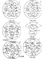
- a hybrid single-phase variable reluctance motor 11 (Fig. 1) of the present invention includes a stator 13 and a rotor 15.
- Stator 13 has first, second, third and fourth inwardly salient teeth 13A, 13B, 13C, and 13D terminating at a central bore indicated generally at 17.
- the four stator teeth are generally evenly spaced around central bore 17. Specifically, the stator teeth are spaced ninety degrees apart around the central bore, with opposed teeth being diametrically disposed with respect to each other across the central bore.
- phase winding 19 is operatively associated with stator teeth 13A and 13B.
- Winding 19 consists of two coils 19A and 19B, discussed below in conjunction with Figs. 3A and 3B.
- Rotor 15 has two outwardly salient teeth disposed generally at 180 degrees with respect to each other.
- the rotor is fixedly secured to a shaft 21 for rotation in central bore 17.
- a permanent magnet 23 is disposed adjacent the central bore at the end of stator tooth 13C. As will become apparent, permanent magnet 23 provides a magnetic detent torque to cause the rotor to come to rest in a preferred position for starting the motor. The magnetic detent torque also provides torque for rotating the rotor during those portions of the operating cycle when the coil-excited reluctance torque is zero or negligible.
- rotor position detecting means are disposed at stator tooth 13D for detecting the rotational position of rotor 15 in central bore 17.
- the rotor position detecting means preferably includes a unipolar Hall effect device or sensor 25. Alternatively, it can include a search coil 27.
- stator teeth 13A, 13B, 13C and 13D are curved, while the ends of rotor teeth 15A and 15B also have a predetermined complementary curvature, as shown.
- Permanent magnet 23 forms the end of stator tooth 13C and has a curvature complementary to the curvature of the rotor teeth, which minimizes the air gap between the magnet and the rotor teeth.
- a less expensive block magnet can be used for magnet 23.
- Magnet 23 is shown as being substantially the same width as the stator tooth on which it is mounted and as the rotor teeth. Alternatively, magnet 23 can be smaller than the stator tooth on which it is mounted, and/or the coil excited and magnet excited stator teeth can have different widths.
- Each tooth of rotor 15 has a shoulder (labelled 15C and 15D in Fig. 1) along its radially outermost surface. These shoulders divide the outermost surface of each tooth into two portions 15E and 15F, portion 15F being farther from the center of rotor 15 than is portion 15E. As a result, there are provided two different air gaps (unlabelled on Fig. 1, but see similar air gaps R A , R B , and R c on Fig. 5) between the rotor teeth and the stator teeth.
- the first gap, between portion 15F and the stator teeth, is designed to be as small as possible to maximize the reluctance effect in the motor during operation.
- the second air gap, between portion 15E and the stator teeth, is somewhat larger.
- the effect of having shoulders 15C and 15D is that the rotor has a preferential direction of rotation. How this occurs is explained below in detail in connection with Figs. 6, 7 and 9.
- Fig. 2 The torque profiles resulting from permanent magnet 23 and winding 19, along with their sum is shown in Fig. 2. Note that in this Fig. the scales differ for the magnet detent torque on the one hand and for the coil excited torque and the sum on the other. The magnet detent torque is of a much smaller absolute magnitude than the coil excited torque. Of course, the exact magnet detent torque curve will depend on the strength and placement of magnet 23 and the configuration of rotor 15.
- the curve for the magnet detent torque includes some negative portions, the sum of that torque and the coil excited torque is always positive, in part because of the difference in magnitudes of the two torques.
- the curve also shows positive and negative portions, the negative portions being cross-hatched.
- This curve represents the torque on rotor 15 assuming that winding 19 is always energized.
- suitable control circuitry is provided (see, for example, Fig. 4) so that the winding is not energized during those portions of the cycle in which the coil excited torque would be negative.
- the cross-hatched portion of the coil excited torque curve is not actually seen by rotor 15.
- the torque sum curve at the bottom of Fig. 2 takes this into account.
- winding 19 The coils of winding 19 are shown in Figs. 3A and 3B.
- winding 19 consists of two bifilar coils 19A and 19B.
- a single power switch Q1 is used to control application of power to the winding.
- Switches Q1, Q3 and Q5 are electronically controlled by control circuitry such as that shown in Fig. 4.
- Fig. 4 shows a bifilar winding 19 connected in series with control switch Q1 across the output of a rectifier bridge 31.
- the input of bridge 31 is connected to a suitable source of AC power, and its output is smoothed by a capacitor C1, all in the conventional manner.
- Rotor position information is supplied to the circuitry of Fig. 4 by unipolar Hall effect device 25.
- This device is shown configured in the current sinking output mode in which the output voltage (on the middle of the three leads from device 25) is High when little or no flux is present and is Low when flux is present.
- the High output of Hall effect device 25 keeps a pnp-type transistor Q7 from conducting while the rotor teeth are not in the vicinity of the Hall effect device.
- the output of device 25 is High when the rotor is in the position shown in Fig. 1.
- a pulse width modulating drive circuit 33 is disposed between transistor Q7 and power switch Q1 to regulate the voltage applied to the winding. Circuit 33 controls the applied voltage in response to a motor voltage reference signal in conventional manner.
- the circuitry of Fig. 4 also includes a current limit circuit 35 connected between power switch Q1 and the negative side of rectifier bridge 31.
- FIG. 5 A second embodiment of the rotor, labelled 45, is shown in Fig. 5. Instead of a single shoulder and two air gaps, rotor 45 has two shoulders S1 and S2 of differing depths and three air gaps R A , R B , and R C . The airgaps are exaggerated for clarity. Rotor 45 is designed to rotate in the counter-clockwise (CCW) direction as seen in the Figs.
- CCW counter-clockwise
- Each tooth of rotor 45 is divided into three arcs A, B, and C (with the associated air gaps R A , R B , and R C ) by shoulders S1 and S2. Of the three gaps, gap R C is the smallest, gap R A is the next smallest and gap R B is the largest.
- the width of gap R A is chosen to provide enough fringe flux to Hall effect device 25 to keep the device output Low while arc A of rotor 45 is passing by the Hall effect device.
- the length of arc A is selected so as to correspond with the desired switching point for winding 19. This maintains the phase current in winding 19 for a long dwell time until the rate of rise of the inductance maximizes in the CCW direction. This arc keeps the Hall effect device activated for a predetermined amount of rotation of the rotor.
- Arc B of rotor 45 is the running start gap on the CCW side of the rotor. It is important that air gap R B for this arc is large enough so that fringing flux through this gap does not turn Hall effect device 25 on. Arc B could be eliminated, but its presence does provide two advantages. First, it gives an increased rate of rise of inductance so more torque is generated as current is rising during the CCW running cycle. Second, it increases the starting torque in the CCW direction for starting.
- Arc C since it has the minimum air gap, provides the main running torque for the motor.
- FIG. 6A illustrates a typical rest position for rotor 45 in which one of the rotor teeth is aligned with permanent magnet 23. This is, of course, one of the two minimum reluctance positions for the magnet excited poles.
- Hall effect device 25 sees flux due to magnet 23.
- the prescribed voltage is applied by the circuitry of Fig. 4 to phase winding 19.
- Current builds up (“X” indicates current flowing into the page in the drawings) until sufficient coil excited flux is created to produce a coil excited reluctance torque greater than the magnet detent torque.
- rotor 45 begins rotating clockwise to the position shown in Fig. 6B.
- Rotor 45 continues CCW rotation under the influence of the reluctance torque due to the phase current.
- the output of Hall effect device 25 remains Low until the position shown in Fig. 7A is reached (because the air gap R A is sufficiently small to allow flux to continue activating the Hall effect device while arc A is passing device 25).
- phase current is zero.
- the torque due to permanent magnet 23 now causes the rotor to rotate an additional ninety degrees CCW.
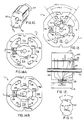
- FIG. 8 A second three-gap design of the rotor, labelled rotor 55, is shown in Fig. 8. This particular design results in a smoother, one-direction start. All motion with this rotor is in the CCW direction, even during starting.
- Rotor 55 like rotor 45, has three air gaps R A , R B , and R C , but the lengths of the three arcs (labelled A1, B1, and C1 for rotor 55) of the rotor differ from those of rotor 45.
- certain relationships between arcs A1, B1, and C1 exist in order to, among other things, maintain the difference between minimum and maximum permeance.
- the difference between 180 degrees and the sum of arcs A1 and B1 (measured in degrees) be equal to or greater than 2.3 times arc C1 (measured in degrees).
- air gap R B of rotor 55 must be great enough that the flux across that gap does not cause the output of Hall effect device 25 to go Low.
- the output of the Hall effect device must not go from High to Low as arc B1 passes the device because that would cause the phase voltage and current to turn on prematurely, resulting in a large current rise.
- air gap R A corresponding to arc A1 must be small enough so that the flux across the gap does cause the output of the Hall effect device to be Low.
- arc B1 must be larger than arc A1 so that the rate of change of permeance is initially higher in the CCW direction. This ensures that rotor starts in the CCW direction and stays in that direction.
- air gap R A is sufficiently small to cause the output of Hall effect device 25 to be Low, that gap must not be as small as gap R C .
- Gap R A must be greater than gap R C so that there is only one stable detent position due to permanent magnet 23.
- arc C1 of rotor 55 provides the running torque for motor 11.
- Figs. 9A - 9C Starting of motor 11 with rotor 55 is illustrated in Figs. 9A - 9C. Starting occurs when the rotor is at the detent rest position shown in Fig. 9A. As power is turned on, Hall effect device 25 sees flux due to permanent magnet 23 and its output is in the Low state. As a result, the phase voltage is applied to phase winding 19. Phase current builds up until the resulting reluctance torque overcomes the detent torque and rotor 55 begins rotating CCW.
- the rotor then rotates CCW until the flux detected by the Hall effect device reduces to the point where the output of device 25 goes High. This position is generally that shown in Fig. 9B.
- the output of Hall effect device 25 goes High, the phase voltage goes to zero and the phase current starts to decay.
- Rotor 55 continues to rotate CCW due to momentum and the reluctance torque caused by the decaying current.
- FIG. 10 A third embodiment of the present invention is illustrated in Figs. 10 - 12. Except for an alternative rotor, labelled 65, the motor 11 of these Figs. is generally the same as that of the previous Figs.
- Rotor 65 differs from the rotors discussed above in that it has an additional steel piece 67 secured to one end of the rotor stack so that it extends past stator 13 on the side of the stator under the Hall effect device (See Fig. 12).
- Piece 67 simplifies the construction of the rotor in several ways. Because the flux through the Hall effect device 25 is controlled by the arc of separate piece 67, the rotor itself has only two gaps, R B and R C , as shown in Fig. 10. Because the separate piece 67 may be secured to rotor 65 at any desired relative rotational position, there is provided increase flexibility in turn on/turn off positions for Hall effect device 25.
- the placement of the separate piece 67 determines the turn on/turn off positions for the Hall effect device, while the width D of the arc defined by piece 67 controls the number of degrees during which the Hall effect device remains in each state.
- control over the amount of flux for the Hall effect device is increased.
- a smaller magnet 23 can be used for the same amount of flux.
- Such a configuration also simplifies the design of motors 11 of various lengths since separate piece 67 makes it easier to insure proper flux levels through Hall effect device 25.
- Fig. 12 while illustrating the structure of the motor of Figs. 10 - 12, also shows some features common to all embodiments of the motor. For example, it is desirable to have a flux concentrator 69, such as a piece of any magnetic steel disposed behind Hall effect device 25 to ensure proper flux levels through the device.
- Device 25 is, as discussed above in connection with the other embodiments, disposed at stator tooth 13D. As shown in Fig. 12, it is mounted at one axial end of that stator tooth adjacent the central bore.
- Fig. 12 also illustrates the fact that both the stator and the rotor of motor 11 are made up of laminations in the conventional manner.
- Permanent magnet 23 is shown axially centered on its stator tooth in Fig. 12. Other configurations are possible, but they can result in axial forces being applied which are undesirable.
- FIG. 13 and 14 A fourth embodiment of the motor 11 is illustrated in Figs. 13 and 14. This embodiment uses rotor 65 and backplate 67 of Figs. 10 - 12 with a stator having several unique features.
- Stator 71 of Figs. 13 and 14 instead of having a shaped magnet 23 has a flat block magnet 23A at the end of stator tooth 71B.
- Flat block magnets offer lower cost for about the same performance in detent torque.
- These magnets may be used in any of the embodiments of the present invention instead of the shaped magnet 23 if desired.
- the motor of Figs. 13 and 14 also differs from the other embodiments in that the coil-excited salient poles 71A have a width greater than the width of the magnet excited salient poles 71B. That is, width "A" shown on Fig. 13 is greater than width "B.”
- Figs. 14A and 14B there are multiple stable or detent positions, such as the two different detent positions shown in Figs. 14A and 14B.
- the worst case position for starting torque is that shown in Fig. 14A. Any other angular position between those shown in Figs. 14A and 14B will improve starting torque over that resulting when the rotor has stopped in the position illustrated in Fig. 14A.
- the reluctance at the area labelled AX in Fig. 13 must be less than the reluctance at the area labelled BX.
- the angle ANGZ in Fig. 13 should be at least 1.3 times as large as the angle ANGA to maintain good min-max reluctance ratios.
- the magnet-salient pole arrangement in all embodiments offer the ability to fill-in torque during the zones when coils 19 are off. This reduces the ratio of torque ripple/average torque in a unique manner with a resulting valuable reduction in the resonant noise of the mechanical system of the motor.
Claims (16)
- Einphasiger, reluktanzveränderlicher Hybridmotor (11), mit:einem Ständer (13), der vier einwärts ausgeprägte Zähne (13A-13D) hat, die aus entgegengesetzten Zähnepaaren (13A-13B, 13C-13D) bestehen, welche um eine zentrale Bohrung (17) beabstandet sind und an der Bohrung endigen;einer Phasenwicklung (19), die einem Paar der Ständerzähne (13A, 13B) operativ zugeordnet ist, welche in bezug aufeinander über der zentralen Bohrung diametral entgegengesetzt sind, wobei die Phasenwicklung, wenn sie erregt ist, eine vorübergehende Magnetisierung dieses einen Ständerzähnepaares bewirkt;einem Läufer (15), der in der zentralen Bohrung drehbar angeordnet ist und ein Paar auswärts ausgeprägter Zähne (15A, 15B) ebenfalls in bezug aufeinander über der zentralen Bohrung diametral entgegengesetzt hat, wobei jeder der Läuferzähne wenigstens eine Schulter (15C, 15D) hat, die längs seiner radial äußersten Oberfläche gebildet ist, wobei die Schultern, wenn sie von dem Zentrum des Läufers aus betrachtet werden, eine Vielzahl von Luftspalten (Ra-Rc) bilden, von denen einer so bemessen ist, daß eine Reluktanzwirkung maximiert wird, die in dem Motor während seines Betriebes auftritt, und wobei die Schultern eine bevorzugte Richtung der Motordrehung während seines Betriebes erzeugen;einem Permanentmagnet (23), der an der zentralen Bohrung an dem Ende eines Zahns (13C) des anderen Ständerzähnepaares (13C, 13D) angeordnet ist; undeiner Einrichtung (25), die dem anderen Zahn (13D) des anderen Zähnepaares zugeordnet ist, zum Erfassen der Drehposition des Läufers in der zentralen Bohrung.
- Reluktanzveränderlicher Motor nach Anspruch 1, wobei jeder Läuferzahn eine vorbestimmte Krümmung hat und wobei das Ende des Permanentmagnets, das der zentralen Bohrung zugewandt ist, eine zu der Krümmung der Läuferzähne komplementäre Krümmung hat.
- Reluktanzveränderlicher Motor nach Anspruch 2, wobei der Permanentmagnet orthogonal zu den Zähnen, die das erste Ständerzähnepaar bilden, positioniert ist.
- Reluktanzveränderlicher Motor nach Anspruch 1, wobei jeder Läuferzahn ein Paar Schultern hat und wobei die Schultern unterschiedliche Tiefen haben, so daß ein erster, ein zweiter und ein dritter Luftspalt zwischen den Läuferzähnen und dem Ständer vorhanden sind.
- Reluktanzveränderlicher Motor nach Anspruch 4, wobei die Läuferzahnschultern, wenn sie von dem Zentrum des Läufers aus betrachtet werden, einen ersten,.einen zweiten und einen dritten Bogen bilden, die dem ersten, zweiten bzw. dritten Luftspalt entsprechen.
- Reluktanzveränderlicher Motor nach Anspruch 5, wobei die Differenz zwischen 180 Grad und der Summe der Gradzahlen, die durch den ersten Bogen und den zweiten Bogen aufgespannt werden, ungefähr gleich dem 2,3-fachen oder größer als das 2,3-fache der durch den dritten Bogen aufgespannten Gradzahl ist.
- Reluktanzveränderlicher Motor nach Anspruch 6, wobei der erste Bogen größer als der zweite Bogen ist und wobei der erste Luftspalt größer als der zweite Luftspalt ist.
- Reluktanzveränderlicher Motor nach Anspruch 1, wobei die Einrichtung zum Erfassen der Läuferposition eine Hall-Vorrichtung aufweist, die an dem axialen Ende des anderen Zahns des anderen Ständerzähnepaares an der zentralen Bohrung befestigt ist.
- Reluktanzveränderlicher Motor nach Anspruch 8, weiter mit einem Flußkonzentrator, der benachbart zu der Hall-Vorrichtung angeordnet ist.
- Reluktanzveränderlicher Motor nach Anspruch 7, wobei die Einrichtung zum Erfassen der Läuferposition eine Hall-Vorrichtung aufweist, wobei der erste Luftspalt zu groß ist, um die Vorrichtung zu aktivieren, und wobei der zweite Luftspalt eine Größe hat, aufgrund welcher die Vorrichtung aktiviert wird.
- Reluktanzveränderlicher Motor nach Anspruch 10, wobei die Größe des zweiten Bogens eine Funktion der Abklingkennlinie der Phasenwicklung ist, so daß die Vorrichtung für ein vorbestimmtes Ausmaß der Läuferdrehung aktiviert gehalten wird.
- Reluktanzveränderlicher Motor nach Anspruch 11, wobei der zweite Luftspalt größer als der dritte Luftspalt ist, damit der dritte Luftspalt eine Halteposition des Läufers bestimmt.
- Reluktanzveränderlicher Motor nach Anspruch 1, wobei die Zähne, die das erste Paar Ständerzähne bilden, breiter sind als die des zweiten Paares.
- Reluktanzveränderlicher Motor nach Anspruch 1, wobei der Winkel, der durch den Teil des Läufers zwischen den Läuferzähnen aufgespannt wird, gemessen von der Drehachse des Motors aus, den Winkel übersteigt, der durch einen ersten Zahn des ersten Ständerzähnepaares aufgespannt wird.
- Reluktanzveränderlicher Motor nach Anspruch 14, wobei der Winkel, der durch den Teil des Läufers zwischen den Läuferzähnen aufgespannt wird, wenigstens das 1,3-fache des Winkels ist, der durch den ersten Zahn des ersten Ständerzähnepaares aufgespannt wird.
- Reluktanzveränderlicher Motor nach Anspruch 1, wobei die Einrichtung zum Erfassen der Drehposition des Läufers eine Suchspule umfaßt.
Applications Claiming Priority (2)
| Application Number | Priority Date | Filing Date | Title |
|---|---|---|---|
| US07/516,280 US5122697A (en) | 1990-04-30 | 1990-04-30 | Hybrid single-phase variable reluctance motor |
| US516280 | 1990-04-30 |
Publications (3)
| Publication Number | Publication Date |
|---|---|
| EP0455578A2 EP0455578A2 (de) | 1991-11-06 |
| EP0455578A3 EP0455578A3 (en) | 1992-01-02 |
| EP0455578B1 true EP0455578B1 (de) | 1996-06-26 |
Family
ID=24054882
Family Applications (1)
| Application Number | Title | Priority Date | Filing Date |
|---|---|---|---|
| EP91630021A Expired - Lifetime EP0455578B1 (de) | 1990-04-30 | 1991-04-18 | Hybrider Einphasenmotor mit veränderlicher Reluktanz |
Country Status (7)
| Country | Link |
|---|---|
| US (1) | US5122697A (de) |
| EP (1) | EP0455578B1 (de) |
| JP (1) | JP3188727B2 (de) |
| KR (1) | KR100229963B1 (de) |
| BR (1) | BR9101714A (de) |
| DE (1) | DE69120467T2 (de) |
| ES (1) | ES2089169T3 (de) |
Cited By (1)
| Publication number | Priority date | Publication date | Assignee | Title |
|---|---|---|---|---|
| DE10244102B4 (de) * | 2002-09-23 | 2017-04-13 | Valeo Wischersysteme Gmbh | Sensoranordnung zum Erfassen einer umdrehungsbezogenen Grösse eines elektrischen Motors |
Families Citing this family (54)
| Publication number | Priority date | Publication date | Assignee | Title |
|---|---|---|---|---|
| KR950000241B1 (ko) * | 1990-01-12 | 1995-01-12 | 배연수 | 동력발생 및 전력발생용 회전장치의 자기회로 및 자기유도 방법 |
| US5294856A (en) * | 1990-04-30 | 1994-03-15 | Emerson Electric Co. | Shifted pole single phase variable reluctance motor |
| JP2573859Y2 (ja) * | 1991-11-21 | 1998-06-04 | 株式会社ハーモニック・ドライブ・システムズ | 電磁式有限回転型電動機の原点復帰機構 |
| US5239217A (en) * | 1992-05-18 | 1993-08-24 | Emerson Electric Co. | Redundant switched reluctance motor |
| GB9225846D0 (en) * | 1992-12-10 | 1993-02-03 | Switched Reluctance Drives Ltd | Further improvements in electric machines |
| DE4345599B4 (de) * | 1993-03-01 | 2006-11-30 | Papst Licensing Gmbh & Co. Kg | Elektromotor |
| IT1268427B1 (it) * | 1993-10-21 | 1997-03-04 | Giorgio Gurrieri | Motore sincrono a riluttanza a poli salienti ad alta resa munito di gabbia in corto circuito |
| CA2151532C (en) * | 1994-07-25 | 1998-12-22 | Emerson Electric Co. | Auxiliary starting switched reluctance motor |
| US5600192A (en) * | 1994-07-29 | 1997-02-04 | Sorvall Products, L.P. | DC electric motor having a flux concentrating member thereon |
| GB9418710D0 (en) * | 1994-09-16 | 1994-11-02 | Switched Reluctance Drives Ltd | Stator for electric machine and lamination thereof |
| US6262510B1 (en) | 1994-09-22 | 2001-07-17 | Iancu Lungu | Electronically switched reluctance motor |
| GB9506461D0 (en) * | 1995-03-29 | 1995-05-17 | Switched Reluctance Drives Ltd | Single-phase variable reluctance motor having permanent magnets bedded within a phase winding |
| GB9506460D0 (en) * | 1995-03-29 | 1995-05-17 | Switched Reluctance Drives Ltd | Apparatus and method for starting a single-phase variable reluctance motor |
| US5852334A (en) * | 1995-10-19 | 1998-12-22 | Tridelta Industries, Inc. | Staggered pole switched reluctance motor |
| US6060809A (en) * | 1995-10-19 | 2000-05-09 | Tridelta Industries, Inc. | Staggered pole switched reluctance motor |
| US6051903A (en) * | 1995-10-19 | 2000-04-18 | Tridelta Industries, Inc. | Switched reluctance motor |
| US6028385A (en) * | 1995-10-19 | 2000-02-22 | Tridelta Industries, Inc. | Switched reluctance motor |
| US5969454A (en) * | 1995-10-19 | 1999-10-19 | Tridelta Industries, Inc. | Switched reluctance motor |
| US5701064A (en) * | 1995-10-27 | 1997-12-23 | Emerson Electric Co. | Rotor position sensing in a dynamoelectric machine using coupling between machine coils |
| US5923142A (en) * | 1996-01-29 | 1999-07-13 | Emerson Electric Co. | Low cost drive for switched reluctance motor with DC-assisted excitation |
| ITPN960017A1 (it) * | 1996-03-12 | 1997-09-12 | Sole Spa | Macchina elettrica, in particolare motore elettrico |
| SE516498C2 (sv) * | 1996-05-30 | 2002-01-22 | Vilmos Toeroek | Självstartande borstlös elektrisk motor |
| US5729112A (en) * | 1996-07-26 | 1998-03-17 | Dana Corporation | Phase current sensing in a bifilar-wound switched reluctance motor drive topology |
| US5982122A (en) * | 1996-12-05 | 1999-11-09 | General Electric Company | Capacitively powered motor and constant speed control therefor |
| GB9715248D0 (en) * | 1997-07-18 | 1997-09-24 | Switched Reluctance Drives Ltd | Starting of single-phase motors |
| JP3554756B2 (ja) * | 1998-12-03 | 2004-08-18 | ミネベア株式会社 | アクチュエータ |
| IT1299526B1 (it) * | 1998-06-18 | 2000-03-16 | Micronasa Di Patarchi Alberto | Motore elettrico universale a traferro variabile |
| JP3466945B2 (ja) | 1999-01-05 | 2003-11-17 | 日本電産株式会社 | 記録ディスク駆動用モータ及びこれを備えた記録ディスク駆動装置 |
| WO2001045235A1 (en) * | 1999-12-17 | 2001-06-21 | MONEGO, Guido | Electronically controlled permanent-magnet electric motor |
| AU2436501A (en) * | 2000-01-03 | 2001-07-16 | Tri-Delta Industries Inc. | Mechanically commutated switched reluctance motor |
| US6720686B1 (en) | 2000-10-03 | 2004-04-13 | Emerson Electric Co. | Reduced noise dynamoelectric machine |
| KR100408052B1 (ko) * | 2001-01-22 | 2003-12-01 | 엘지전자 주식회사 | 회전 왕복동식 영구자석형 모터 |
| KR100408051B1 (ko) * | 2001-01-22 | 2003-12-01 | 엘지전자 주식회사 | 회전 왕복동식 영구자석형 모터 |
| DE10126413A1 (de) * | 2001-05-31 | 2002-12-05 | Bosch Gmbh Robert | Zweiphasiger, geschalteter Reluktanzmotor |
| GB2376572B (en) | 2001-06-11 | 2005-06-22 | Roger Barry Hobby | Flux impulse motor |
| JP4581640B2 (ja) * | 2004-11-17 | 2010-11-17 | トヨタ自動車株式会社 | 車両駆動システムおよびそれを備える車両 |
| DE102005045546A1 (de) | 2005-09-23 | 2007-03-29 | Vorwerk & Co. Interholding Gmbh | Reluktanzmotor |
| KR100754944B1 (ko) | 2005-12-20 | 2007-09-04 | 대동모벨시스템 주식회사 | 단상 스위치드 릴럭턴스 모터 |
| US20070182270A1 (en) * | 2006-02-08 | 2007-08-09 | Jaquar Precision Industry Co., Ltd. | Motor stator device |
| JP2007306782A (ja) * | 2006-04-14 | 2007-11-22 | Japan Servo Co Ltd | 単相モータ |
| RU2497265C2 (ru) * | 2011-03-23 | 2013-10-27 | Александр Владимирович Карасев | Генератор постоянного тока |
| US20130033125A1 (en) * | 2011-08-03 | 2013-02-07 | Kabushiki Kaisha Yaskawa Denki | Linear motor armature and linear motor |
| KR101255960B1 (ko) * | 2011-11-29 | 2013-04-23 | 삼성전기주식회사 | 스위치드 릴럭턴스 모터 |
| RU2524144C2 (ru) * | 2012-03-19 | 2014-07-27 | Федеральное государственное автономное образовательное учреждение высшего профессионального образования "Уральский федеральный университет имени первого Президента России Б.Н. Ельцина" | Однофазная электрическая машина |
| DE102013102124A1 (de) | 2013-03-04 | 2014-09-04 | Ebm-Papst St. Georgen Gmbh & Co. Kg | Einphasiger Elektromotor |
| JP6269818B2 (ja) | 2014-04-02 | 2018-01-31 | 株式会社Ihi | ダブルステータ型スイッチトリラクタンス回転機 |
| KR101644572B1 (ko) * | 2014-07-16 | 2016-08-03 | 주식회사 에스엔이노베이션 | 스위치드 릴럭턴스 모터 |
| JP6406355B2 (ja) | 2014-10-17 | 2018-10-17 | 株式会社Ihi | ダブルステータ型回転機 |
| KR101893262B1 (ko) * | 2016-11-04 | 2018-08-29 | 경성대학교 산학협력단 | 복합 공극을 가지는 단상 하이브리드 srm |
| KR101893261B1 (ko) * | 2016-11-04 | 2018-08-30 | 경성대학교 산학협력단 | 비균일 공극을 가지는 단상 하이브리드 srm |
| KR101893289B1 (ko) * | 2017-02-07 | 2018-08-29 | 경성대학교 산학협력단 | 영구자석 빠짐 방지 모터 |
| CN106849578B (zh) * | 2017-03-20 | 2019-02-15 | 山东理工大学 | 一种四相永磁双凸极电机 |
| CN107104569B (zh) * | 2017-07-04 | 2023-04-25 | 杭州同孚环保科技有限公司 | 一种采用线圈永磁体组合定子的电机 |
| CN111711299B (zh) * | 2020-08-04 | 2023-01-24 | 珠海格力电器股份有限公司 | 单相永磁自起动电机及具有其的电动设备 |
Family Cites Families (8)
| Publication number | Priority date | Publication date | Assignee | Title |
|---|---|---|---|---|
| DD133736A1 (de) * | 1977-10-17 | 1979-01-17 | Dietrich Storn | Elektrische maschine mit hybrid-permanentmagnet-erregung |
| JPS5990279U (ja) * | 1982-12-07 | 1984-06-19 | 山洋電気株式会社 | 永久磁石回転子形電動機 |
| NL8401336A (nl) * | 1984-04-26 | 1985-11-18 | Philips Nv | Eenfase reluktantiemotor. |
| DE3582783D1 (de) * | 1984-11-20 | 1991-06-13 | S G Kk | Einrichtung zum erfassen der drehlage. |
| JPS6223352A (ja) * | 1985-07-15 | 1987-01-31 | Shikoo Giken:Kk | 一相通電されるブラシレスモ−タ |
| JPS6281473U (de) * | 1985-11-07 | 1987-05-25 | ||
| FR2632465A1 (fr) * | 1988-06-03 | 1989-12-08 | Ventilation Electricite Appliq | Moteur electrique a commutation electronique, notamment pour l'entrainement d'une machine de deplacement d'un fluide, en particulier un seche-cheveux, equipee d'un tel moteur |
| DE9003028U1 (de) * | 1990-02-06 | 1990-08-02 | Menge, Eberhard, Dipl.-Ing., 7313 Reichenbach, De |
-
1990
- 1990-04-30 US US07/516,280 patent/US5122697A/en not_active Expired - Lifetime
-
1991
- 1991-04-09 BR BR919101714A patent/BR9101714A/pt not_active IP Right Cessation
- 1991-04-18 EP EP91630021A patent/EP0455578B1/de not_active Expired - Lifetime
- 1991-04-18 ES ES91630021T patent/ES2089169T3/es not_active Expired - Lifetime
- 1991-04-18 DE DE69120467T patent/DE69120467T2/de not_active Expired - Fee Related
- 1991-04-24 JP JP12217191A patent/JP3188727B2/ja not_active Expired - Fee Related
- 1991-04-25 KR KR1019910006628A patent/KR100229963B1/ko not_active IP Right Cessation
Cited By (1)
| Publication number | Priority date | Publication date | Assignee | Title |
|---|---|---|---|---|
| DE10244102B4 (de) * | 2002-09-23 | 2017-04-13 | Valeo Wischersysteme Gmbh | Sensoranordnung zum Erfassen einer umdrehungsbezogenen Grösse eines elektrischen Motors |
Also Published As
| Publication number | Publication date |
|---|---|
| JPH06205571A (ja) | 1994-07-22 |
| ES2089169T3 (es) | 1996-10-01 |
| DE69120467T2 (de) | 1996-10-31 |
| BR9101714A (pt) | 1991-12-10 |
| JP3188727B2 (ja) | 2001-07-16 |
| DE69120467D1 (de) | 1996-08-01 |
| EP0455578A2 (de) | 1991-11-06 |
| KR100229963B1 (ko) | 1999-11-15 |
| US5122697A (en) | 1992-06-16 |
| EP0455578A3 (en) | 1992-01-02 |
| KR910019308A (ko) | 1991-11-30 |
Similar Documents
| Publication | Publication Date | Title |
|---|---|---|
| EP0455578B1 (de) | Hybrider Einphasenmotor mit veränderlicher Reluktanz | |
| EP0695020B1 (de) | Anlaufhilfe für einen getakteten Reluktanzmotor | |
| US5548173A (en) | Switched reluctance motors | |
| JP2549538B2 (ja) | 磁気増大型可変リラクタンスモータシステム | |
| US4704567A (en) | Brushless D.C. motor having alternating wider and narrower pole shoes | |
| US5773908A (en) | Single phase motor with positive torque parking positions | |
| US5041749A (en) | High speed, high power, single phase brushless DC motor | |
| USRE37576E1 (en) | Single phase motor with positive torque parking positions | |
| CA2097194C (en) | Polyphase switched reluctance motor | |
| US4748362A (en) | D. C. motor with multi-tooth poles | |
| US4450396A (en) | Electrically controlled synchronous machine | |
| US20030218399A1 (en) | Internal rotor motor | |
| WO1990002437A1 (en) | An electric motor | |
| US4751415A (en) | Brushless DC motor with means for compensating ripple torque | |
| GB2171260A (en) | Variable reluctance motor | |
| US4950960A (en) | Electronically commutated motor having an increased flat top width in its back EMF waveform, a rotatable assembly therefor, and methods of their operation | |
| JPH0638475A (ja) | 永久磁石回転電機とその制御方法及び制御装置並びにそれを使用した電気自動車 | |
| JP3797488B2 (ja) | 多極回転電機 | |
| JP2667815B2 (ja) | ブラシレス電動機 | |
| KR100408052B1 (ko) | 회전 왕복동식 영구자석형 모터 | |
| GB2341732A (en) | Layout of rotor poles in an electric motor | |
| JPH0713427Y2 (ja) | ブラシレスモ−タ | |
| JPH09168265A (ja) | 同期・誘導複合電機及び同期電機 | |
| RU2241298C1 (ru) | Электрическая машина | |
| JP2641198B2 (ja) | ブラシレスモータ |
Legal Events
| Date | Code | Title | Description |
|---|---|---|---|
| PUAI | Public reference made under article 153(3) epc to a published international application that has entered the european phase |
Free format text: ORIGINAL CODE: 0009012 |
|
| AK | Designated contracting states |
Kind code of ref document: A2 Designated state(s): DE ES FR GB IT SE |
|
| PUAL | Search report despatched |
Free format text: ORIGINAL CODE: 0009013 |
|
| AK | Designated contracting states |
Kind code of ref document: A3 Designated state(s): DE ES FR GB IT SE |
|
| 17P | Request for examination filed |
Effective date: 19920617 |
|
| 17Q | First examination report despatched |
Effective date: 19950207 |
|
| GRAG | Despatch of communication of intention to grant |
Free format text: ORIGINAL CODE: EPIDOS AGRA |
|
| GRAH | Despatch of communication of intention to grant a patent |
Free format text: ORIGINAL CODE: EPIDOS IGRA |
|
| GRAH | Despatch of communication of intention to grant a patent |
Free format text: ORIGINAL CODE: EPIDOS IGRA |
|
| GRAA | (expected) grant |
Free format text: ORIGINAL CODE: 0009210 |
|
| AK | Designated contracting states |
Kind code of ref document: B1 Designated state(s): DE ES FR GB IT SE |
|
| ET | Fr: translation filed | ||
| REF | Corresponds to: |
Ref document number: 69120467 Country of ref document: DE Date of ref document: 19960801 |
|
| ITF | It: translation for a ep patent filed |
Owner name: UFFICIO BREVETTI RICCARDI & C. |
|
| REG | Reference to a national code |
Ref country code: ES Ref legal event code: FG2A Ref document number: 2089169 Country of ref document: ES Kind code of ref document: T3 |
|
| REG | Reference to a national code |
Ref country code: ES Ref legal event code: FG2A Ref document number: 2089169 Country of ref document: ES Kind code of ref document: T3 |
|
| PLBE | No opposition filed within time limit |
Free format text: ORIGINAL CODE: 0009261 |
|
| STAA | Information on the status of an ep patent application or granted ep patent |
Free format text: STATUS: NO OPPOSITION FILED WITHIN TIME LIMIT |
|
| 26N | No opposition filed | ||
| REG | Reference to a national code |
Ref country code: GB Ref legal event code: IF02 |
|
| PGFP | Annual fee paid to national office [announced via postgrant information from national office to epo] |
Ref country code: SE Payment date: 20020319 Year of fee payment: 12 |
|
| PGFP | Annual fee paid to national office [announced via postgrant information from national office to epo] |
Ref country code: ES Payment date: 20020408 Year of fee payment: 12 |
|
| PGFP | Annual fee paid to national office [announced via postgrant information from national office to epo] |
Ref country code: FR Payment date: 20030311 Year of fee payment: 14 |
|
| PG25 | Lapsed in a contracting state [announced via postgrant information from national office to epo] |
Ref country code: SE Free format text: LAPSE BECAUSE OF NON-PAYMENT OF DUE FEES Effective date: 20030419 Ref country code: ES Free format text: LAPSE BECAUSE OF NON-PAYMENT OF DUE FEES Effective date: 20030419 |
|
| EUG | Se: european patent has lapsed | ||
| PGFP | Annual fee paid to national office [announced via postgrant information from national office to epo] |
Ref country code: DE Payment date: 20040330 Year of fee payment: 14 |
|
| REG | Reference to a national code |
Ref country code: ES Ref legal event code: FD2A Effective date: 20030419 |
|
| PGFP | Annual fee paid to national office [announced via postgrant information from national office to epo] |
Ref country code: GB Payment date: 20050413 Year of fee payment: 15 |
|
| PG25 | Lapsed in a contracting state [announced via postgrant information from national office to epo] |
Ref country code: IT Free format text: LAPSE BECAUSE OF NON-PAYMENT OF DUE FEES;WARNING: LAPSES OF ITALIAN PATENTS WITH EFFECTIVE DATE BEFORE 2007 MAY HAVE OCCURRED AT ANY TIME BEFORE 2007. THE CORRECT EFFECTIVE DATE MAY BE DIFFERENT FROM THE ONE RECORDED. Effective date: 20050418 |
|
| PG25 | Lapsed in a contracting state [announced via postgrant information from national office to epo] |
Ref country code: DE Free format text: LAPSE BECAUSE OF NON-PAYMENT OF DUE FEES Effective date: 20051101 |
|
| PG25 | Lapsed in a contracting state [announced via postgrant information from national office to epo] |
Ref country code: FR Free format text: LAPSE BECAUSE OF NON-PAYMENT OF DUE FEES Effective date: 20051230 |
|
| REG | Reference to a national code |
Ref country code: FR Ref legal event code: ST Effective date: 20051230 |
|
| PG25 | Lapsed in a contracting state [announced via postgrant information from national office to epo] |
Ref country code: GB Free format text: LAPSE BECAUSE OF NON-PAYMENT OF DUE FEES Effective date: 20060418 |
|
| GBPC | Gb: european patent ceased through non-payment of renewal fee |
Effective date: 20060418 |