EP0455519B1 - Hydrostatisch angetriebene Achse eines Gabelstaplers - Google Patents
Hydrostatisch angetriebene Achse eines Gabelstaplers Download PDFInfo
- Publication number
- EP0455519B1 EP0455519B1 EP91400546A EP91400546A EP0455519B1 EP 0455519 B1 EP0455519 B1 EP 0455519B1 EP 91400546 A EP91400546 A EP 91400546A EP 91400546 A EP91400546 A EP 91400546A EP 0455519 B1 EP0455519 B1 EP 0455519B1
- Authority
- EP
- European Patent Office
- Prior art keywords
- motor
- hydrostatic
- frame
- motors
- assembly
- Prior art date
- Legal status (The legal status is an assumption and is not a legal conclusion. Google has not performed a legal analysis and makes no representation as to the accuracy of the status listed.)
- Expired - Lifetime
Links
Images


Classifications
-
- B—PERFORMING OPERATIONS; TRANSPORTING
- B66—HOISTING; LIFTING; HAULING
- B66F—HOISTING, LIFTING, HAULING OR PUSHING, NOT OTHERWISE PROVIDED FOR, e.g. DEVICES WHICH APPLY A LIFTING OR PUSHING FORCE DIRECTLY TO THE SURFACE OF A LOAD
- B66F9/00—Devices for lifting or lowering bulky or heavy goods for loading or unloading purposes
- B66F9/06—Devices for lifting or lowering bulky or heavy goods for loading or unloading purposes movable, with their loads, on wheels or the like, e.g. fork-lift trucks
- B66F9/075—Constructional features or details
- B66F9/07509—Braking
-
- B—PERFORMING OPERATIONS; TRANSPORTING
- B60—VEHICLES IN GENERAL
- B60K—ARRANGEMENT OR MOUNTING OF PROPULSION UNITS OR OF TRANSMISSIONS IN VEHICLES; ARRANGEMENT OR MOUNTING OF PLURAL DIVERSE PRIME-MOVERS IN VEHICLES; AUXILIARY DRIVES FOR VEHICLES; INSTRUMENTATION OR DASHBOARDS FOR VEHICLES; ARRANGEMENTS IN CONNECTION WITH COOLING, AIR INTAKE, GAS EXHAUST OR FUEL SUPPLY OF PROPULSION UNITS IN VEHICLES
- B60K17/00—Arrangement or mounting of transmissions in vehicles
- B60K17/04—Arrangement or mounting of transmissions in vehicles characterised by arrangement, location, or kind of gearing
- B60K17/14—Arrangement or mounting of transmissions in vehicles characterised by arrangement, location, or kind of gearing the motor of fluid or electric gearing being disposed in or adjacent to traction wheel
-
- B—PERFORMING OPERATIONS; TRANSPORTING
- B66—HOISTING; LIFTING; HAULING
- B66F—HOISTING, LIFTING, HAULING OR PUSHING, NOT OTHERWISE PROVIDED FOR, e.g. DEVICES WHICH APPLY A LIFTING OR PUSHING FORCE DIRECTLY TO THE SURFACE OF A LOAD
- B66F9/00—Devices for lifting or lowering bulky or heavy goods for loading or unloading purposes
- B66F9/06—Devices for lifting or lowering bulky or heavy goods for loading or unloading purposes movable, with their loads, on wheels or the like, e.g. fork-lift trucks
- B66F9/075—Constructional features or details
- B66F9/07572—Propulsion arrangements
Definitions
- US-A-3,005,562 represents a forklift which has a hydrostatic bridge comprising a frame, two displacement members coupled to motors and a handling mast pivoting relative to said frame, this bridge comprising two motor assemblies, right and left, each assembly comprising a hydrostatic motor and a brake and being coupled to one of said displacement members.
- the hydrostatic motors are fast motors, necessarily associated with speed reducers, the assembly being housed in a bulky casing, itself rigidly fixed to the heat engine driving the hydraulic pump supplying the hydrostatic motors.
- the handling mast is pivotally mounted directly relative to the carriage frame.
- the invention intends to remedy these drawbacks by eliminating speed reducers by adopting slow hydrostatic motors, and by providing for pivoting mounting of the mast relative to the bridge itself.
- the main advantage of the invention lies in the small size, the saving in weight and the good rigidity of the hydrostatic bridge, as well as in the great simplicity of its assembly.
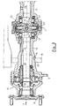
- FIG. 3 shows the conventional details of the hydrostatic motors 13, as well as the output shaft 15 of the hydrostatic motor 13 located on the left in the figure.
- the covers 22, disposed facing the internal ends of the two shafts 15, are also arranged opposite one another.
- a reaction ring 25, mounted freely floating between these two covers 22, constitutes a support for two elastic washers 26, forming springs, interposed, each, between said reaction ring 25 and a cover 22.
- the elastic effect of the washers 26 is , specifically, to push the covers 22 towards the respective stacks 21 in the direction leading to the braking of the rotation of the corresponding shaft 28 relative to the beam 12.
- Each brake constitutes a safety brake, including the brake release chamber is constituted by chamber 24.
- the bulge 14 which houses the brake discs 21 and their control (chamber 24, elastic washer 26), is located in the central position of the beam 12, between the two bearings (19- 20) of the pivoting mounting of the handling mast 8 on the beam 12.
- the invention which has just been described therefore allows, by adoption slow hydrostatic motors 13, capable of directly driving the wheels 7 without the interposition of speed reducers, and associated brakes, to house the assembly in a single beam 12, which is fixed (5-6) on the frame 1 of the carriage independently of the heat engine 11 and the hydraulic pump 2.
- the pivoting mounting of the handling mast 8 directly on the beam 12 makes assembly easier.
- the rigidity of the beam 12 allows such mounting.
- the safety brakes (14-21) are coupled to the wheels 7 without any reduction, directly by means of the shafts 15 and 28 of the hydrostatic motors 13, which is a guarantee of efficiency and reliability.
Landscapes
- Engineering & Computer Science (AREA)
- Transportation (AREA)
- Structural Engineering (AREA)
- Mechanical Engineering (AREA)
- Chemical & Material Sciences (AREA)
- Combustion & Propulsion (AREA)
- Civil Engineering (AREA)
- Life Sciences & Earth Sciences (AREA)
- Geology (AREA)
- Forklifts And Lifting Vehicles (AREA)
Claims (5)
- Hydrostatisch angetriebene Achse eines Gabelstaplers, bestehend aus einem Fahrgestell (1), zwei Verfahrorganen (7), die mit Motoren (13) gekoppelt sind, und einen Hubmast (8), der kippbar zu dem genannten Fahrgestell angebracht ist, wobei diese Achse zwei Antriebseinheiten, eine linke und eine rechte, aufweist, wobei jede Einheit aus einem Hydrostatikmotor (13) und einer Bremse (14, 21) besteht und mit einem der genannten Verfahrorgane (7) gekoppelt ist, dadurch gekennzeichnet, daßa) der Hydrostatikmotor (13) jeder der genannten Einheiten ein langsam laufender Motor ist, dergestalt daß kein Getriebe zwischen dem Verfahrorgan (7) und diesem langsam laufenden Motor zwischengeschaltet ist;b) die beiden Motoren (13) und die beiden Bremsen (14, 21) in einem festen einzelnen Träger (12) untergebracht sind, der an dem Fahrgestell (1) des Gabelstaplers befestigt ist (6, 6); undc) der Hubmast (8) über wenigstens zwei Schwenklager (19, 20) kippbar an dem genannten Träger (12) angebaut ist.
- Hydrostatisch angetriebene Achse nach Anspruch 1, dadurch gekennzeichnet, daß sich die Bremsen (14, 21) zwischen den beiden Schwenklagern (19, 20) befinden.
- Hydrostatisch angetriebene Achse nach einem der Ansprüche 1 und 2,
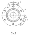
dadurch gekennzeichnet, daß der Träger am Fahrgestell mit zwei Befestigungsflanschs (5) angebracht ist, die sich beide in einer zu den Abtriebswellen (15, 28) der beiden Motoren etwa senkrecht liegenden Ebene befinden. - Hydrostatisch angetriebene Achse nach einem der Ansprüche 1 bis 3,
dadurch gekennzeichnet, daß bei jeder Antriebseinheit der Motor ein mit dem einzelnen Träger (12) drehfest verbundenes Gehäuse (13) sowie eine zu dem genannten Gehäuse (13) drehbar gelagerte Abtriebswelle (15, 28) aufweist, wobei die Bremse der genannten Antriebseinheit einerseits aus einem Bremsscheibenpaket (21) und andererseits aus einem federnden Schubteil (26) für die Bremsscheiben des Pakets besteht, während die federnden Teile (26) der Bremsen der beiden Antriebseinheiten in Druckanlage aneinander kommen. - Hydrostatisch angetriebene Achse nach Anspruch 4, dadurch gekennzeichnet, daß ein Gegendruckring (25) zwischen den genannten federnden Teilen (26) angeordnet ist.
Applications Claiming Priority (2)
| Application Number | Priority Date | Filing Date | Title |
|---|---|---|---|
| FR9005671 | 1990-04-05 | ||
| FR9005671A FR2661666B1 (fr) | 1990-05-04 | 1990-05-04 | Pont hydrostatique de chariot elevateur. |
Publications (2)
| Publication Number | Publication Date |
|---|---|
| EP0455519A1 EP0455519A1 (de) | 1991-11-06 |
| EP0455519B1 true EP0455519B1 (de) | 1993-09-22 |
Family
ID=9396358
Family Applications (1)
| Application Number | Title | Priority Date | Filing Date |
|---|---|---|---|
| EP91400546A Expired - Lifetime EP0455519B1 (de) | 1990-05-04 | 1991-02-28 | Hydrostatisch angetriebene Achse eines Gabelstaplers |
Country Status (5)
| Country | Link |
|---|---|
| US (1) | US5152658A (de) |
| EP (1) | EP0455519B1 (de) |
| JP (1) | JP3343133B2 (de) |
| DE (1) | DE69100392T2 (de) |
| FR (1) | FR2661666B1 (de) |
Families Citing this family (10)
| Publication number | Priority date | Publication date | Assignee | Title |
|---|---|---|---|---|
| DE4305639C2 (de) * | 1993-02-24 | 1996-05-30 | Jungheinrich Ag | Hublader |
| FR2706539B1 (fr) * | 1993-06-14 | 1995-09-01 | Poclain Hydraulics Sa | Ensemble de deux moteurs à fluide sous pression. |
| DE19849770B4 (de) * | 1998-10-28 | 2016-03-03 | Linde Material Handling Gmbh | Gabelstapler |
| DE19849753B4 (de) * | 1998-10-28 | 2008-05-08 | Linde Material Handling Gmbh | Flurförderzeug mit einem Heckgewicht und einem Verbrennungsmotor |
| DE19908201B4 (de) * | 1999-02-25 | 2016-03-03 | Linde Material Handling Gmbh | Gabelstapler und Verfahren zur Montage eines Gabelstaplers |
| DE10029881B4 (de) * | 2000-06-16 | 2010-06-24 | Linde Material Handling Gmbh | Gabelstapler |
| DE10129782B4 (de) * | 2001-06-20 | 2018-01-04 | Linde Material Handling Gmbh | Flurförderzeug mit einer Antriebseinheit, die an einem benachbarten Rahmenabschnitt eines Fahrzeugrahmens befestigt ist. |
| DE10319610B4 (de) * | 2002-05-11 | 2011-06-16 | Linde Material Handling Gmbh | Flurförderzeug mit einem neigbaren Hubgerüst, das mit einem dreh- und/oder schwenkbar an einem Fahrzeugrahmen gelagerten Achskörper befestigt ist |
| DE10325127A1 (de) * | 2003-06-04 | 2004-12-23 | Linde Ag | Antriebseinrichtung mit einem Fahrantrieb und einer Arbeitshydraulik |
| CN102821995B (zh) * | 2011-03-29 | 2014-03-26 | 株式会社小松制作所 | 电动叉车 |
Family Cites Families (11)
| Publication number | Priority date | Publication date | Assignee | Title |
|---|---|---|---|---|
| FR1215143A (fr) * | 1958-11-06 | 1960-04-14 | Freins Jourdain Monneret | Perfectionnements aux chariots élévateurs |
| US3005562A (en) * | 1959-10-29 | 1961-10-24 | Towmotor Corp | Hydraulic drive for lift truck |
| US3098574A (en) * | 1961-06-08 | 1963-07-23 | Heifred Corp | Hydraulically driven industrial truck |
| US3219219A (en) * | 1963-08-14 | 1965-11-23 | Minneapolis Moline Inc | Frame structure and engine arrangement for an industrial truck |
| US3439766A (en) * | 1966-12-29 | 1969-04-22 | Clark Equipment Co | Hydraulic-motor-in-wheel assembly |
| US3376990A (en) * | 1967-07-26 | 1968-04-09 | Clark Equipment Co | Drive assembly and mast mounting means for an industrial vehicle |
| US3721318A (en) * | 1971-03-19 | 1973-03-20 | Total Power Hydraulics Ltd | Lift trucks |
| US3831718A (en) * | 1972-11-24 | 1974-08-27 | Caterpillar Tractor Co | Parking brake assembly for track-type vehicles |
| US3863038A (en) * | 1973-06-26 | 1975-01-28 | Lambert & Brake Corp | Disc brake |
| US4207968A (en) * | 1978-02-21 | 1980-06-17 | Caterpillar Tractor Co. | Double disc type brake system |
| US4606428A (en) * | 1985-04-18 | 1986-08-19 | Eaton Corporation | Transaxle differential |
-
1990
- 1990-05-04 FR FR9005671A patent/FR2661666B1/fr not_active Expired - Fee Related
-
1991
- 1991-02-28 DE DE91400546T patent/DE69100392T2/de not_active Expired - Fee Related
- 1991-02-28 EP EP91400546A patent/EP0455519B1/de not_active Expired - Lifetime
- 1991-03-11 US US07/667,662 patent/US5152658A/en not_active Expired - Lifetime
- 1991-05-07 JP JP13024091A patent/JP3343133B2/ja not_active Expired - Fee Related
Also Published As
| Publication number | Publication date |
|---|---|
| DE69100392D1 (de) | 1993-10-28 |
| DE69100392T2 (de) | 1994-01-20 |
| EP0455519A1 (de) | 1991-11-06 |
| JPH0655947A (ja) | 1994-03-01 |
| US5152658A (en) | 1992-10-06 |
| FR2661666B1 (fr) | 1992-08-28 |
| JP3343133B2 (ja) | 2002-11-11 |
| FR2661666A1 (fr) | 1991-11-08 |
Similar Documents
| Publication | Publication Date | Title |
|---|---|---|
| EP0878332B1 (de) | Einheit mit einem Rad und einer in einer Radnabe eingebauten Aufhängung | |
| EP2361830B1 (de) | Landefahrwerk mit Vorrichtung zum Antrieb vom Fahrwerksrad | |
| EP1799471B1 (de) | Fahrzeugbodenverbindung mit einem rad und einer darin integrierten aufhängung | |
| EP0455519B1 (de) | Hydrostatisch angetriebene Achse eines Gabelstaplers | |
| EP1912848A1 (de) | Elektrisches lenksystem für fahrzeug | |
| EP0366509B1 (de) | Bremse mit zwei Scheiben mit festem Abstand | |
| FR2693154A1 (fr) | Ensemble d'un organe de déplacement moteur et du dispositif de son montage à pivotement. | |
| FR2958227A1 (fr) | Ensemble motopropulseur | |
| EP0414836B1 (de) | Fahrzeug mit verstellbarer lenkradgeometrie | |
| EP0966620B1 (de) | Hybrides mehrscheibenbremssystem | |
| FR2461632A1 (fr) | Dispositif d'entrainement d'une chenille | |
| EP1053409B1 (de) | Scheibenbremse mit ausgeglichener reaktion | |
| EP0404880A1 (de) | Kraft- oder schleppfahrzeug mit nabenlosen rädern. | |
| EP0615502B1 (de) | Hochleistungshilfskraftlenkung | |
| WO2003044387A1 (fr) | Tambour de freinage de masse reduite et a performances augmentees | |
| EP3395640B1 (de) | Drehgestell eines schienenfahrzeugs, das ein bremssystem mit drei bremsscheiben umfasst, die zwischen den achsengehäusen angeordnet sind | |
| FR2560563A1 (fr) | Dispositif de propulsion et de freinage combine avec une roue de vehicule et son utilisation dans un chargeur pour avions | |
| FR2621960A1 (fr) | Mecanisme a fluide sous pression muni d'un rotor monte rotatif par rapport a un stator au moyen d'un palier de rotation | |
| FR2493237A1 (fr) | Vehicule amphibie | |
| FR2688175A3 (en) | Hydraulically driven automotive vehicle | |
| FR2728321A1 (fr) | Dispositif de freinage a disques d'une roue de vehicule | |
| FR2744679A1 (fr) | Transmission de vehicule equipee d'un ralentisseur electrique | |
| WO2010079375A1 (fr) | Dispositif de production de couple, notamment dispositif d'orientation | |
| FR2537073A1 (fr) | Dispositif de freinage, notamment pour vehicule a roues entrainees par des transmissions separees | |
| FR2892482A1 (fr) | Dispositif de transmission de puissance |
Legal Events
| Date | Code | Title | Description |
|---|---|---|---|
| PUAI | Public reference made under article 153(3) epc to a published international application that has entered the european phase |
Free format text: ORIGINAL CODE: 0009012 |
|
| AK | Designated contracting states |
Kind code of ref document: A1 Designated state(s): DE FR GB IT |
|
| 17P | Request for examination filed |
Effective date: 19911014 |
|
| 17Q | First examination report despatched |
Effective date: 19920916 |
|
| GRAA | (expected) grant |
Free format text: ORIGINAL CODE: 0009210 |
|
| AK | Designated contracting states |
Kind code of ref document: B1 Designated state(s): DE FR GB IT |
|
| REF | Corresponds to: |
Ref document number: 69100392 Country of ref document: DE Date of ref document: 19931028 |
|
| GBT | Gb: translation of ep patent filed (gb section 77(6)(a)/1977) |
Effective date: 19931013 |
|
| ITF | It: translation for a ep patent filed |
Owner name: DR. ING. A. RACHELI & C |
|
| PLBE | No opposition filed within time limit |
Free format text: ORIGINAL CODE: 0009261 |
|
| STAA | Information on the status of an ep patent application or granted ep patent |
Free format text: STATUS: NO OPPOSITION FILED WITHIN TIME LIMIT |
|
| 26N | No opposition filed | ||
| REG | Reference to a national code |
Ref country code: FR Ref legal event code: TP |
|
| REG | Reference to a national code |
Ref country code: GB Ref legal event code: 732E |
|
| REG | Reference to a national code |
Ref country code: GB Ref legal event code: IF02 |
|
| PGFP | Annual fee paid to national office [announced via postgrant information from national office to epo] |
Ref country code: DE Payment date: 20090211 Year of fee payment: 19 |
|
| PGFP | Annual fee paid to national office [announced via postgrant information from national office to epo] |
Ref country code: GB Payment date: 20090209 Year of fee payment: 19 |
|
| PGFP | Annual fee paid to national office [announced via postgrant information from national office to epo] |
Ref country code: IT Payment date: 20090217 Year of fee payment: 19 |
|
| PGFP | Annual fee paid to national office [announced via postgrant information from national office to epo] |
Ref country code: FR Payment date: 20090219 Year of fee payment: 19 |
|
| GBPC | Gb: european patent ceased through non-payment of renewal fee |
Effective date: 20100228 |
|
| REG | Reference to a national code |
Ref country code: FR Ref legal event code: ST Effective date: 20101029 |
|
| PG25 | Lapsed in a contracting state [announced via postgrant information from national office to epo] |
Ref country code: FR Free format text: LAPSE BECAUSE OF NON-PAYMENT OF DUE FEES Effective date: 20100301 |
|
| PG25 | Lapsed in a contracting state [announced via postgrant information from national office to epo] |
Ref country code: DE Free format text: LAPSE BECAUSE OF NON-PAYMENT OF DUE FEES Effective date: 20100901 |
|
| PG25 | Lapsed in a contracting state [announced via postgrant information from national office to epo] |
Ref country code: IT Free format text: LAPSE BECAUSE OF NON-PAYMENT OF DUE FEES Effective date: 20100228 Ref country code: GB Free format text: LAPSE BECAUSE OF NON-PAYMENT OF DUE FEES Effective date: 20100228 |