EP0455519B1 - Hydrostatically driven axle for a fork lift truck - Google Patents
Hydrostatically driven axle for a fork lift truck Download PDFInfo
- Publication number
- EP0455519B1 EP0455519B1 EP91400546A EP91400546A EP0455519B1 EP 0455519 B1 EP0455519 B1 EP 0455519B1 EP 91400546 A EP91400546 A EP 91400546A EP 91400546 A EP91400546 A EP 91400546A EP 0455519 B1 EP0455519 B1 EP 0455519B1
- Authority
- EP
- European Patent Office
- Prior art keywords
- motor
- hydrostatic
- frame
- motors
- assembly
- Prior art date
- Legal status (The legal status is an assumption and is not a legal conclusion. Google has not performed a legal analysis and makes no representation as to the accuracy of the status listed.)
- Expired - Lifetime
Links
Images


Classifications
-
- B—PERFORMING OPERATIONS; TRANSPORTING
- B66—HOISTING; LIFTING; HAULING
- B66F—HOISTING, LIFTING, HAULING OR PUSHING, NOT OTHERWISE PROVIDED FOR, e.g. DEVICES WHICH APPLY A LIFTING OR PUSHING FORCE DIRECTLY TO THE SURFACE OF A LOAD
- B66F9/00—Devices for lifting or lowering bulky or heavy goods for loading or unloading purposes
- B66F9/06—Devices for lifting or lowering bulky or heavy goods for loading or unloading purposes movable, with their loads, on wheels or the like, e.g. fork-lift trucks
- B66F9/075—Constructional features or details
- B66F9/07509—Braking
-
- B—PERFORMING OPERATIONS; TRANSPORTING
- B60—VEHICLES IN GENERAL
- B60K—ARRANGEMENT OR MOUNTING OF PROPULSION UNITS OR OF TRANSMISSIONS IN VEHICLES; ARRANGEMENT OR MOUNTING OF PLURAL DIVERSE PRIME-MOVERS IN VEHICLES; AUXILIARY DRIVES FOR VEHICLES; INSTRUMENTATION OR DASHBOARDS FOR VEHICLES; ARRANGEMENTS IN CONNECTION WITH COOLING, AIR INTAKE, GAS EXHAUST OR FUEL SUPPLY OF PROPULSION UNITS IN VEHICLES
- B60K17/00—Arrangement or mounting of transmissions in vehicles
- B60K17/04—Arrangement or mounting of transmissions in vehicles characterised by arrangement, location, or kind of gearing
- B60K17/14—Arrangement or mounting of transmissions in vehicles characterised by arrangement, location, or kind of gearing the motor of fluid or electric gearing being disposed in or adjacent to traction wheel
-
- B—PERFORMING OPERATIONS; TRANSPORTING
- B66—HOISTING; LIFTING; HAULING
- B66F—HOISTING, LIFTING, HAULING OR PUSHING, NOT OTHERWISE PROVIDED FOR, e.g. DEVICES WHICH APPLY A LIFTING OR PUSHING FORCE DIRECTLY TO THE SURFACE OF A LOAD
- B66F9/00—Devices for lifting or lowering bulky or heavy goods for loading or unloading purposes
- B66F9/06—Devices for lifting or lowering bulky or heavy goods for loading or unloading purposes movable, with their loads, on wheels or the like, e.g. fork-lift trucks
- B66F9/075—Constructional features or details
- B66F9/07572—Propulsion arrangements
Definitions
- US-A-3,005,562 represents a forklift which has a hydrostatic bridge comprising a frame, two displacement members coupled to motors and a handling mast pivoting relative to said frame, this bridge comprising two motor assemblies, right and left, each assembly comprising a hydrostatic motor and a brake and being coupled to one of said displacement members.
- the hydrostatic motors are fast motors, necessarily associated with speed reducers, the assembly being housed in a bulky casing, itself rigidly fixed to the heat engine driving the hydraulic pump supplying the hydrostatic motors.
- the handling mast is pivotally mounted directly relative to the carriage frame.
- the invention intends to remedy these drawbacks by eliminating speed reducers by adopting slow hydrostatic motors, and by providing for pivoting mounting of the mast relative to the bridge itself.
- the main advantage of the invention lies in the small size, the saving in weight and the good rigidity of the hydrostatic bridge, as well as in the great simplicity of its assembly.
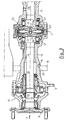
- FIG. 3 shows the conventional details of the hydrostatic motors 13, as well as the output shaft 15 of the hydrostatic motor 13 located on the left in the figure.
- the covers 22, disposed facing the internal ends of the two shafts 15, are also arranged opposite one another.
- a reaction ring 25, mounted freely floating between these two covers 22, constitutes a support for two elastic washers 26, forming springs, interposed, each, between said reaction ring 25 and a cover 22.
- the elastic effect of the washers 26 is , specifically, to push the covers 22 towards the respective stacks 21 in the direction leading to the braking of the rotation of the corresponding shaft 28 relative to the beam 12.
- Each brake constitutes a safety brake, including the brake release chamber is constituted by chamber 24.
- the bulge 14 which houses the brake discs 21 and their control (chamber 24, elastic washer 26), is located in the central position of the beam 12, between the two bearings (19- 20) of the pivoting mounting of the handling mast 8 on the beam 12.
- the invention which has just been described therefore allows, by adoption slow hydrostatic motors 13, capable of directly driving the wheels 7 without the interposition of speed reducers, and associated brakes, to house the assembly in a single beam 12, which is fixed (5-6) on the frame 1 of the carriage independently of the heat engine 11 and the hydraulic pump 2.
- the pivoting mounting of the handling mast 8 directly on the beam 12 makes assembly easier.
- the rigidity of the beam 12 allows such mounting.
- the safety brakes (14-21) are coupled to the wheels 7 without any reduction, directly by means of the shafts 15 and 28 of the hydrostatic motors 13, which is a guarantee of efficiency and reliability.
Description
US-A- 3 005 562 représente un chariot élévateur qui possède un pont hydrostatique comportant un bâti, deux organes de déplacement attelés à des moteurs et un mât de manutention pivotant par rapport audit bâti, ce pont comprenant deux ensembles moteurs, droit et gauche, chaque ensemble comprenant un moteur hydrostatique et un frein et étant attelé à l'un desdits organes de déplacement.US-A-3,005,562 represents a forklift which has a hydrostatic bridge comprising a frame, two displacement members coupled to motors and a handling mast pivoting relative to said frame, this bridge comprising two motor assemblies, right and left, each assembly comprising a hydrostatic motor and a brake and being coupled to one of said displacement members.
Dans ce chariot connu, les moteurs hydrostatiques sont des moteurs rapides, nécessairement associés à des réducteurs de vitesse, l'ensemble étant abrité dans un carter volumineux, lui-même fixé rigidement au moteur thermique d'entraînement de la pompe hydraulique d'alimentation des moteurs hydrostatiques. Le mât de manutention est monté pivotant directement par rapport au bâti du chariot.In this known carriage, the hydrostatic motors are fast motors, necessarily associated with speed reducers, the assembly being housed in a bulky casing, itself rigidly fixed to the heat engine driving the hydraulic pump supplying the hydrostatic motors. The handling mast is pivotally mounted directly relative to the carriage frame.
Cette construction est lourde, coûteuse et ne permet pas un montage simple, ni du pont lui-même, ni du mât sur le chariot.This construction is heavy, expensive and does not allow a simple assembly, neither of the bridge itself, nor of the mast on the carriage.
L'invention entend remédier à ces inconvénients en supprimant les réducteurs de vitesse grâce à l'adoption de moteurs hydrostatiques lents, et en prévoyant le montage à pivotement du mât par rapport au pont lui-même.The invention intends to remedy these drawbacks by eliminating speed reducers by adopting slow hydrostatic motors, and by providing for pivoting mounting of the mast relative to the bridge itself.
Ainsi, selon l'invention, les caractéristiques suivantes sont prévues :
- a) le moteur hydrostatique de chacun desdits ensembles est un moteur lent, de sorte qu'aucun réducteur de vitesse n'est interposé entre l'organe de déplacement et le moteur lent;
- b) les deux moteurs et les deux freins sont contenus dans une poutre résistante unique fixée sur le bâti du chariot ; et,
- c) le mât de manutention est monté pivotant sur ladite poutre par l'intermédiaire d'au moins deux paliers de pivotement.
- a) the hydrostatic motor of each of said assemblies is a slow motor, so that no speed reducer is interposed between the displacement member and the slow motor;
- b) the two motors and the two brakes are contained in a single resistant beam fixed to the frame of the carriage; and,
- c) the handling mast is pivotally mounted on said beam by means of at least two pivot bearings.
Les avantageuses dispositions suivantes sont en outre de préférence adoptées :
- les freins sont situés entre les deux paliers de pivotement ;
- la poutre est fixée au châssis par deux brides de fixation qui sont, chacune, contenue dans un plan sensiblement perpendiculaire aux arbres de sortie des deux moteurs ;
- dans chaque ensemble-moteur, le moteur comporte un bâti solidaire, vis-à-vis de la rotation, de la poutre unique, et, un arbre de sortie monté à rotation par rapport audit bâti, le frein dudit ensemble-moteur comportant, d'une part un empilage de disques de frein, d'autre part un organe élastique de poussée des disques de frein dudit empilage, cependant que les organes élastiques des freins des deux ensembles-moteurs prennent appui de réaction l'un sur l'autre ;
- une bague de réaction est interposée entre lesdits organes élastiques.
- the brakes are located between the two pivot bearings;
- the beam is fixed to the chassis by two fixing flanges which are each contained in a plane substantially perpendicular to the output shafts of the two motors;
- in each engine assembly, the engine has a frame integral with the rotation, the single beam, and an output shaft rotatably mounted relative to said frame, the brake of said motor assembly comprising, on the one hand a stack of brake discs, d on the other hand an elastic member for pushing the brake discs of said stack, while the elastic members for the brakes of the two engine assemblies bear reaction support one on the other;
- a reaction ring is interposed between said elastic members.
L'avantage principal de l'invention réside dans le faible encombrement, l'économie de poids et la bonne rigidité du pont hydrostatique, ainsi que dans la grande simplicité de son montage.The main advantage of the invention lies in the small size, the saving in weight and the good rigidity of the hydrostatic bridge, as well as in the great simplicity of its assembly.
L'invention sera mieux comprise, et des caractéristiques secondaires et leurs avantages apparaîtront au cours de la description d'une réalisation donnée ci-dessous à titre d'exemple.The invention will be better understood, and secondary characteristics and their advantages will appear during the description of an embodiment given below by way of example.
Il est entendu que la description et les dessins ne sont donnés qu'à titre indicatif et non limitatif.It is understood that the description and the drawings are given for information only and are not limiting.
Il sera fait référence aux dessins annexés, dans lesquels :
- la figure 1 est une vue en élévation d'un chariot élévateur conforme à l'invention ;
- la figure 2 est une vue suivant flèche G de la figure 1 ;
- la figure 3 est une coupe longitudinale partielle du pont de la figure 2 ; et,
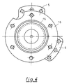
- la figure 4 est une vue suivant flèche F de la figure 3.
- Figure 1 is an elevational view of a forklift according to the invention;
- Figure 2 is a view along arrow G of Figure 1;
- Figure 3 is a partial longitudinal section of the bridge of Figure 2; and,
- FIG. 4 is a view along arrow F of FIG. 3.
La figure 1 représente la partie avant d'un chariot élévateur comprenant :
- le
bâti 1 proprement dit du chariot ; - un moteur thermique 11, du type "Diesel", auquel est attelée une pompe hydraulique 2, et qui est monté, en l'espèce au moyen de supports élastiques 3, sur la
bâti 1 ; - un
pont moteur 4, qui est fixé sur lebâti 1 par desbrides 5 et desboulons 6 ; - des roues avant 7 fixées aux extrémités du
pont moteur 4 ; - un mât de
manutention 8 qui est monté pivotant autour de l'axe géométrique 9 dupont moteur 4, unvérin 10 étant attelé entre ce mât demanutention 8 et lebâti 1 et étant apte à régler l'inclinaison dudit mât demanutention 8 par rapport à la direction verticale (débattement angulaire A, au plus égal à 12°).
- the
frame 1 proper of the carriage; - a
heat engine 11, of the "Diesel" type, to which ahydraulic pump 2 is coupled, and which is mounted, in this case by means ofelastic supports 3, on theframe 1; - a
motor bridge 4, which is fixed to theframe 1 byflanges 5 andbolts 6; - front wheels 7 fixed to the ends of the
drive axle 4; - a
handling mast 8 which is pivotally mounted around thegeometric axis 9 of theengine bridge 4, ajack 10 being coupled between thishandling mast 8 and theframe 1 and being able to adjust the inclination of saidhandling mast 8 relative to the vertical direction (angular movement A, at most equal to 12 °).
La figure 2 montre la constitution du pont moteur qui comprend :
- une poutre unique 12, dans chacune des extrémités de laquelle est logé un moteur hydrostatique 13 ;
- un renflement médian 14, qui abrite des freins à disques ;
- deux
arbres moteurs 15, qui constituent les arbres de sortie des deux moteurs hydrostatiques 13 et qui supportent des flasques d'extrémité 16 sur lesquels sont fixées, par desécrous 17, les roues 7, lesbrides 5 étant contenues dans des plans perpendiculaires à l'axe 9 desarbres 15. Lesarbres 15 sont montés à rotation (palier 27) dans et par rapport à la poutre.
- a
single beam 12, in each end of which is housed ahydrostatic motor 13; - a
middle bulge 14, which houses disc brakes; - two
motor shafts 15, which constitute the output shafts of the twohydrostatic motors 13 and which supportend flanges 16 on which are fixed, bynuts 17, the wheels 7, theflanges 5 being contained in planes perpendicular to theaxis 9 of theshafts 15. Theshafts 15 are rotatably mounted (bearing 27) in and with respect to the beam.
On note, en regard de la figure 2, le montage pivotant du mât de manutention 8 directement sur la poutre 12, au moyen de deux bras 18 solidaires du mât de manutention 8 qui s'étendent perpendiculairement à l'axe 9 des arbres 15 et sont munis d'alésages 19 constituant des paliers lisses pour deux portées 20 ménagées sur la face extérieure de la poutre 12.Note, with reference to FIG. 2, the pivoting mounting of the
Il convient d'ailleurs de remarquer que si, dans la réalisation représentée, les axes des alésages 19 sont confondus avec l'axe géométrique 9 du pont moteur 4, il s'agit d'une réalisation particulière non limitative de l'invention. Ainsi, d'autres réalisations conformes à l'invention ont déjà été étudiées, dans lesquelles des paires de pattes de montage de tourillons sont solidaires de la poutre 12 et permettent le montage de tourillons excentrés par rapport à l'axe géométrique 9, ces tourillons coopérant avec d'autres pattes solidaires du mât de manutention 8, pour réaliser le montage pivotant du mât de manutention 8 autour des axes de tourillons. Cette variante de réalisation conserve l'avantage principal lié au montage direct du mât de manutention sur la poutre, qui réside notamment dans une déjà grande facilité d'assemblage du mât de manutention 9 et de la poutre 12, tout en facilitant encore le montage à pivotement du mât de manutention 8 par rapport à la poutre 12. Il devient en particulier possible avec cette variante de réalisation de réaliser le montage du mât de manutention 8 d'un seul côté de la poutre 12 par rapport à l'axe géométrique 9, en évitant de devoir entourer cette poutre 12 par les alésages 19 de la réalisation représentée sur les figures 2 et 3.It should also be noted that if, in the embodiment shown, the axes of the
La coupe de la figure 3 montre les détails, classiques, des moteurs hydrostatiques 13, ainsi que l'arbre de sortie 15 du moteur hydrostatique 13 situé à gauche sur la figure. Un autre arbre 28, solidaire en rotation de l'arbre 15 et sortant du côté opposé à celui du flasque 16 de fixation des roues, est muni d'un jeu de disques de frein qui est contenu à l'intérieur du renflement 14 et qui, avec un deuxième jeu de disques de frein solidaires de la poutre 12, constitue un empilage 21 de disques de frein. Dans la réalisation représentée, un couvercle 22, interne à la poutre 12, monté coulissant à l'intérieur d'un alésage 23 de cette poutre, délimite avec ladite poutre 12 une chambre 24 à l'intérieur de laquelle est contenu l'empilage 21. Ce couvercle 22 constitue une pièce de poussée des disques de frein de l'empilage 21. Les couvercles 22, disposés en regard des extrémités internes des deux arbres 15, sont en outre disposés en regard l'un de l'autre. Une bague de réaction 25, montée librement flottante entre ces deux couvercles 22, constitue un appui pour deux rondelles élastiques 26, formant ressorts, interposées, chacune, entre ladite bague de réaction 25 et un couvercle 22. L'effet élastique des rondelles 26 est, précisément, de pousser les couvercles 22 vers les empilages 21 respectifs dans le sens conduisant à réaliser le freinage de la rotation de l'arbre 28 correspondant par rapport à la poutre 12. Chaque frein constitue un frein de sécurité, dont la chambre de défreinage est constituée par la chambre 24.The section of FIG. 3 shows the conventional details of the
A noter, en regard de la figure 2, que le renflement 14 qui abrite les disques de frein 21 et leur commande (chambre 24, rondelle élastique 26), est situé en position centrale de la poutre 12, entre les deux paliers (19-20) du montage pivotant du mât de manutention 8 sur la poutre 12.Note, with reference to Figure 2, that the
L'invention qui vient d'être décrite permet donc, par adoption de moteurs hydrostatiques lents 13, aptes à entraîner directement les roues 7 sans interposition de réducteurs de vitesse, et de freins associés, de loger l'ensemble dans une seule poutre 12, qui est fixée (5-6) sur le bâti 1 du chariot de manière indépendante du moteur thermique 11 et de la pompe hydraulique 2.The invention which has just been described therefore allows, by adoption slow
Cette disposition est moins encombrante et moins lourde que celles connues antérieurement, et est également plus aisée à installer que celle dans laquelle le carter de pont moteur est solidaire du moteur thermique.This arrangement is less bulky and less cumbersome than those known previously, and is also easier to install than that in which the crankcase is integral with the heat engine.
Par ailleurs, le montage à pivotement du mât de manutention 8 directement sur la poutre 12 rend l'assemblage plus facile. La rigidité de la poutre 12 permet un tel montage.Furthermore, the pivoting mounting of the
Enfin, les freins de sécurité (14-21) sont attelés aux roues 7 sans aucune démultiplication, directement au moyen des arbres 15 et 28 des moteurs hydrostatiques 13, ce qui est gage d'efficacité et de fiabilité.Finally, the safety brakes (14-21) are coupled to the wheels 7 without any reduction, directly by means of the
Claims (5)
- Hydrostatic axle for a lift truck comprising a frame (1), two displacement members (7) coupled to motors (13) and a handling mast (8) mounted to pivot with respect to said frame, this axle comprising two motor-assemblies, right- and left-hand, each assembly comprising a hydrostatic motor (13) and a brake (14-21) being coupled to one of said displacement members (7). characterized in thata) the hydrostatic motor (13) of each of said assemblies is a slow motor such that no speed reducer is interposed between the displacement member (7) and this slow motor;b) the two motors (13) and the two brakes (14-21) are contained in a single resistant beam (12) fixed (5-6) on the frame (1) of the truck; andc) the handling mast (8) is pivotally mounted on said beam (12) via at least two pivot bearings (19-20).
- Hydrostatic axle according to claim 1, characterized in that the brakes (14-21) are located between the two pivot bearings (19-20).
- Hydrostatic axle according to any one of claims 1 and 2, characterized in that the beam is fixed to the chassis by two fixing flanges (5) which are each contained in a plane substantially perpendicular to the driven shafts (15-28) of the two motors.
- Hydrostatic axle according to any one of claims 1 to 3, characterized in that, in each motor-assembly, the motor comprises a frame (13) fast, with respect to rotation, with the single beam (12) and a driven shaft (15-28) mounted to rotate with respect to said frame (13), the brake of said motor-assembly comprising, on the one hand, a stack of brake discs (21), on the other hand, an elastic member (26) for thrust of the brake discs of said stack, whilst the elastic members (26) of the brakes of the two motor-assemblies abut on one another by reaction.
- Hydrostatic axle according to claim 4, characterized in that a reaction ring (25) is interposed between said elastic members (26).
Applications Claiming Priority (2)
| Application Number | Priority Date | Filing Date | Title |
|---|---|---|---|
| FR9005671 | 1990-05-04 | ||
| FR9005671A FR2661666B1 (en) | 1990-05-04 | 1990-05-04 | HYDROSTATIC LIFT TRUCK BRIDGE. |
Publications (2)
| Publication Number | Publication Date |
|---|---|
| EP0455519A1 EP0455519A1 (en) | 1991-11-06 |
| EP0455519B1 true EP0455519B1 (en) | 1993-09-22 |
Family
ID=9396358
Family Applications (1)
| Application Number | Title | Priority Date | Filing Date |
|---|---|---|---|
| EP91400546A Expired - Lifetime EP0455519B1 (en) | 1990-05-04 | 1991-02-28 | Hydrostatically driven axle for a fork lift truck |
Country Status (5)
| Country | Link |
|---|---|
| US (1) | US5152658A (en) |
| EP (1) | EP0455519B1 (en) |
| JP (1) | JP3343133B2 (en) |
| DE (1) | DE69100392T2 (en) |
| FR (1) | FR2661666B1 (en) |
Families Citing this family (10)
| Publication number | Priority date | Publication date | Assignee | Title |
|---|---|---|---|---|
| DE4305639C2 (en) * | 1993-02-24 | 1996-05-30 | Jungheinrich Ag | Lift loader |
| FR2706539B1 (en) * | 1993-06-14 | 1995-09-01 | Poclain Hydraulics Sa | Set of two pressurized fluid motors. |
| DE19849753B4 (en) * | 1998-10-28 | 2008-05-08 | Linde Material Handling Gmbh | Truck with a rear weight and an internal combustion engine |
| DE19849770B4 (en) * | 1998-10-28 | 2016-03-03 | Linde Material Handling Gmbh | fork-lift truck |
| DE19908201B4 (en) * | 1999-02-25 | 2016-03-03 | Linde Material Handling Gmbh | Forklift and method for assembling a forklift |
| DE10029881B4 (en) * | 2000-06-16 | 2010-06-24 | Linde Material Handling Gmbh | fork-lift truck |
| DE10129782B4 (en) * | 2001-06-20 | 2018-01-04 | Linde Material Handling Gmbh | Truck with a drive unit which is attached to an adjacent frame portion of a vehicle frame. |
| DE10319610B4 (en) * | 2002-05-11 | 2011-06-16 | Linde Material Handling Gmbh | Truck with a tilting mast, which is mounted with a rotatably mounted and / or pivotally mounted on a vehicle frame axle body |
| DE10325127A1 (en) * | 2003-06-04 | 2004-12-23 | Linde Ag | Drive device for working machine with propulsion drive and operating hydraulics has first and second electric motors and pumps driven by them combined into assembly perpendicular to drive axle |
| CN102821995B (en) * | 2011-03-29 | 2014-03-26 | 株式会社小松制作所 | Electric forklift |
Family Cites Families (11)
| Publication number | Priority date | Publication date | Assignee | Title |
|---|---|---|---|---|
| FR1215143A (en) * | 1958-11-06 | 1960-04-14 | Freins Jourdain Monneret | Forklift upgrades |
| US3005562A (en) * | 1959-10-29 | 1961-10-24 | Towmotor Corp | Hydraulic drive for lift truck |
| US3098574A (en) * | 1961-06-08 | 1963-07-23 | Heifred Corp | Hydraulically driven industrial truck |
| US3219219A (en) * | 1963-08-14 | 1965-11-23 | Minneapolis Moline Inc | Frame structure and engine arrangement for an industrial truck |
| US3439766A (en) * | 1966-12-29 | 1969-04-22 | Clark Equipment Co | Hydraulic-motor-in-wheel assembly |
| US3376990A (en) * | 1967-07-26 | 1968-04-09 | Clark Equipment Co | Drive assembly and mast mounting means for an industrial vehicle |
| US3721318A (en) * | 1971-03-19 | 1973-03-20 | Total Power Hydraulics Ltd | Lift trucks |
| US3831718A (en) * | 1972-11-24 | 1974-08-27 | Caterpillar Tractor Co | Parking brake assembly for track-type vehicles |
| US3863038A (en) * | 1973-06-26 | 1975-01-28 | Lambert & Brake Corp | Disc brake |
| US4207968A (en) * | 1978-02-21 | 1980-06-17 | Caterpillar Tractor Co. | Double disc type brake system |
| US4606428A (en) * | 1985-04-18 | 1986-08-19 | Eaton Corporation | Transaxle differential |
-
1990
- 1990-05-04 FR FR9005671A patent/FR2661666B1/en not_active Expired - Fee Related
-
1991
- 1991-02-28 EP EP91400546A patent/EP0455519B1/en not_active Expired - Lifetime
- 1991-02-28 DE DE91400546T patent/DE69100392T2/en not_active Expired - Fee Related
- 1991-03-11 US US07/667,662 patent/US5152658A/en not_active Expired - Lifetime
- 1991-05-07 JP JP13024091A patent/JP3343133B2/en not_active Expired - Fee Related
Also Published As
| Publication number | Publication date |
|---|---|
| FR2661666A1 (en) | 1991-11-08 |
| JPH0655947A (en) | 1994-03-01 |
| EP0455519A1 (en) | 1991-11-06 |
| JP3343133B2 (en) | 2002-11-11 |
| FR2661666B1 (en) | 1992-08-28 |
| DE69100392D1 (en) | 1993-10-28 |
| DE69100392T2 (en) | 1994-01-20 |
| US5152658A (en) | 1992-10-06 |
Similar Documents
| Publication | Publication Date | Title |
|---|---|---|
| EP0878332B1 (en) | Unit comprising a wheel and a suspension integrated in the wheel hub | |
| EP2361830B1 (en) | Landing gear wheel assembly provided with a wheel rotation device | |
| EP0455519B1 (en) | Hydrostatically driven axle for a fork lift truck | |
| EP1912848A1 (en) | Electrical steering system for vehicle | |
| WO2011114008A1 (en) | Motor-driven hub including an electric traction machine | |
| FR2949421A1 (en) | TRACK CONTROL DEVICE FOR NARROW ELECTRIC MOTORIZED VEHICLE AND INCLINED TILT | |
| WO1998049046A1 (en) | Bicycle rear suspension | |
| EP0366509B1 (en) | Brake with two fixedly spaced discs | |
| FR2958227A1 (en) | MOTOR POWERS | |
| EP0414836B1 (en) | Vehicle with variable geometry steering wheel | |
| FR2693154A1 (en) | Hydraulic motor and pivot mount for direct drive to automobile wheel - has pressurised fluid motor with stator pivotably mounted on frame and rotor rotatively mounted w.r.t stator, with stator having three internal chambers, and motor including unique rotating joint | |
| EP0966620B1 (en) | Hybrid multiple disc brake | |
| EP0191674A1 (en) | Pressurized-fluid mechanism for a rotor | |
| FR2461632A1 (en) | DEVICE FOR DRIVING A TRACK | |
| EP1053409B1 (en) | Disk brake with balanced reaction | |
| WO2003044387A1 (en) | Reduced mass brake drum with enhanced performances | |
| FR2560563A1 (en) | PROPULSION AND BRAKING DEVICE COMBINED WITH A VEHICLE WHEEL AND ITS USE IN AN AIRCRAFT CHARGER | |
| FR2621960A1 (en) | PRESSURIZED FLUID MECHANISM WITH ROTATING ROTARY ROTOR IN RELATION TO A STATOR USING A ROTATION BEARING | |
| FR2493237A1 (en) | AMPHIBIOUS VEHICLE | |
| EP0000974B1 (en) | Motorised roll for supporting and driving a rotatable cyclindrical body, having a horizontal or slightly inclined axis | |
| FR2688175A3 (en) | Hydraulically driven automotive vehicle | |
| WO1994008836A1 (en) | High performance power steering | |
| FR2744679A1 (en) | VEHICLE TRANSMISSION EQUIPPED WITH AN ELECTRIC RETARDER | |
| WO2010079375A1 (en) | Device for producing torque, in particular an orientation device | |
| FR2537073A1 (en) | BRAKING DEVICE, IN PARTICULAR FOR A VEHICLE WITH WHEELS DRIVEN BY SEPARATE TRANSMISSIONS |
Legal Events
| Date | Code | Title | Description |
|---|---|---|---|
| PUAI | Public reference made under article 153(3) epc to a published international application that has entered the european phase |
Free format text: ORIGINAL CODE: 0009012 |
|
| AK | Designated contracting states |
Kind code of ref document: A1 Designated state(s): DE FR GB IT |
|
| 17P | Request for examination filed |
Effective date: 19911014 |
|
| 17Q | First examination report despatched |
Effective date: 19920916 |
|
| GRAA | (expected) grant |
Free format text: ORIGINAL CODE: 0009210 |
|
| AK | Designated contracting states |
Kind code of ref document: B1 Designated state(s): DE FR GB IT |
|
| REF | Corresponds to: |
Ref document number: 69100392 Country of ref document: DE Date of ref document: 19931028 |
|
| GBT | Gb: translation of ep patent filed (gb section 77(6)(a)/1977) |
Effective date: 19931013 |
|
| ITF | It: translation for a ep patent filed |
Owner name: DR. ING. A. RACHELI & C |
|
| PLBE | No opposition filed within time limit |
Free format text: ORIGINAL CODE: 0009261 |
|
| STAA | Information on the status of an ep patent application or granted ep patent |
Free format text: STATUS: NO OPPOSITION FILED WITHIN TIME LIMIT |
|
| 26N | No opposition filed | ||
| REG | Reference to a national code |
Ref country code: FR Ref legal event code: TP |
|
| REG | Reference to a national code |
Ref country code: GB Ref legal event code: 732E |
|
| REG | Reference to a national code |
Ref country code: GB Ref legal event code: IF02 |
|
| PGFP | Annual fee paid to national office [announced via postgrant information from national office to epo] |
Ref country code: DE Payment date: 20090211 Year of fee payment: 19 |
|
| PGFP | Annual fee paid to national office [announced via postgrant information from national office to epo] |
Ref country code: GB Payment date: 20090209 Year of fee payment: 19 |
|
| PGFP | Annual fee paid to national office [announced via postgrant information from national office to epo] |
Ref country code: IT Payment date: 20090217 Year of fee payment: 19 |
|
| PGFP | Annual fee paid to national office [announced via postgrant information from national office to epo] |
Ref country code: FR Payment date: 20090219 Year of fee payment: 19 |
|
| GBPC | Gb: european patent ceased through non-payment of renewal fee |
Effective date: 20100228 |
|
| REG | Reference to a national code |
Ref country code: FR Ref legal event code: ST Effective date: 20101029 |
|
| PG25 | Lapsed in a contracting state [announced via postgrant information from national office to epo] |
Ref country code: FR Free format text: LAPSE BECAUSE OF NON-PAYMENT OF DUE FEES Effective date: 20100301 |
|
| PG25 | Lapsed in a contracting state [announced via postgrant information from national office to epo] |
Ref country code: DE Free format text: LAPSE BECAUSE OF NON-PAYMENT OF DUE FEES Effective date: 20100901 |
|
| PG25 | Lapsed in a contracting state [announced via postgrant information from national office to epo] |
Ref country code: IT Free format text: LAPSE BECAUSE OF NON-PAYMENT OF DUE FEES Effective date: 20100228 Ref country code: GB Free format text: LAPSE BECAUSE OF NON-PAYMENT OF DUE FEES Effective date: 20100228 |