EP0966620B1 - Hybrides mehrscheibenbremssystem - Google Patents
Hybrides mehrscheibenbremssystem Download PDFInfo
- Publication number
- EP0966620B1 EP0966620B1 EP98908173A EP98908173A EP0966620B1 EP 0966620 B1 EP0966620 B1 EP 0966620B1 EP 98908173 A EP98908173 A EP 98908173A EP 98908173 A EP98908173 A EP 98908173A EP 0966620 B1 EP0966620 B1 EP 0966620B1
- Authority
- EP
- European Patent Office
- Prior art keywords
- disc
- internal
- upstream
- external
- stator
- Prior art date
- Legal status (The legal status is an assumption and is not a legal conclusion. Google has not performed a legal analysis and makes no representation as to the accuracy of the status listed.)
- Expired - Lifetime
Links
- 238000011144 upstream manufacturing Methods 0.000 claims description 28
- 239000000463 material Substances 0.000 description 2
- 238000009423 ventilation Methods 0.000 description 2
- OKTJSMMVPCPJKN-UHFFFAOYSA-N Carbon Chemical compound [C] OKTJSMMVPCPJKN-UHFFFAOYSA-N 0.000 description 1
- 229910001018 Cast iron Inorganic materials 0.000 description 1
- 230000001154 acute effect Effects 0.000 description 1
- 229910052799 carbon Inorganic materials 0.000 description 1
- 230000000717 retained effect Effects 0.000 description 1
Images


Classifications
-
- F—MECHANICAL ENGINEERING; LIGHTING; HEATING; WEAPONS; BLASTING
- F16—ENGINEERING ELEMENTS AND UNITS; GENERAL MEASURES FOR PRODUCING AND MAINTAINING EFFECTIVE FUNCTIONING OF MACHINES OR INSTALLATIONS; THERMAL INSULATION IN GENERAL
- F16D—COUPLINGS FOR TRANSMITTING ROTATION; CLUTCHES; BRAKES
- F16D55/00—Brakes with substantially-radial braking surfaces pressed together in axial direction, e.g. disc brakes
- F16D55/02—Brakes with substantially-radial braking surfaces pressed together in axial direction, e.g. disc brakes with axially-movable discs or pads pressed against axially-located rotating members
- F16D55/025—Brakes with substantially-radial braking surfaces pressed together in axial direction, e.g. disc brakes with axially-movable discs or pads pressed against axially-located rotating members with two or more rotating discs at least one of them being located axially
-
- F—MECHANICAL ENGINEERING; LIGHTING; HEATING; WEAPONS; BLASTING
- F16—ENGINEERING ELEMENTS AND UNITS; GENERAL MEASURES FOR PRODUCING AND MAINTAINING EFFECTIVE FUNCTIONING OF MACHINES OR INSTALLATIONS; THERMAL INSULATION IN GENERAL
- F16D—COUPLINGS FOR TRANSMITTING ROTATION; CLUTCHES; BRAKES
- F16D2121/00—Type of actuator operation force
- F16D2121/02—Fluid pressure
- F16D2121/04—Fluid pressure acting on a piston-type actuator, e.g. for liquid pressure
Definitions
- Braking devices of this type are known in the prior art, as illustrated by example by patent document FR-2 314 399.
- multi-disc brakes are best known in their application to trucks or utility vehicles.
- the braking device of the invention is essentially characterized in that the clamping means further include: a sliding bracket having an upstream end and an end downstream spaced from each other in a direction tangential to the rotor and succeeding in this order in the direction of direct rotation, this sliding bracket carrying the first cylinder between its two ends, overlapping the first disc, and having a nose disposed between the two discs, the first external shoe, the first disc and the first internal shoe being thus clamped between the first piston and the nose of the sliding caliper; fixed guide means upstream and downstream, integral with the stator, and mobile upstream and downstream guide means, respectively secured to the upstream and downstream ends of the sliding bracket, the movable means upstream and downstream guide being respectively slidably mounted relative to the means fixed upstream and downstream guides to ensure sliding of the sliding bracket relative to stator.
- a sliding bracket having an upstream end and an end downstream spaced from each other in a direction tangential to the rotor and succeeding in this order in the direction of direct rotation, this sliding bracket carrying the
- the compactness of this device can be further improved by providing that the nose of the stirrup sliding comprises two parts separated by a free space, and that the second cylinder internal is placed in this free space.
- the two discs can thus in particular be made of different materials.
- the rotor shaped as a hub between the first and second discs, or pierced with holes allowing ventilation of the internal faces of the discs.
- the axes of symmetry of the first and second cylinders can be confused, it can also be preferable that the axis of symmetry of the first cylinder be more advanced, in the direct direction of rotation, as the axes of symmetry of the second cylinders.
- the first internal and external pads can be hooked to the stator by their upstream ends respective, that is to say by those of their respective ends which are recessed in the direct direction of rotation, while these pads rest on the stator by their downstream ends respectively.
- At least one connecting means may include a screw forming a column, this column constituting at least one of the upstream and downstream guide means.
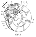
- FIGS. 1 and 2 show a braking device comprising a stator 10 fixed to the vehicle by a fixing arm 5, forming an integral part of a fixed part not shown of the vehicle, such as a rocket carrier, or being made integral with this fixed part, for example by screwing.
- the fixing arm 5 is turned towards the external face 14 of a first disc 13, which is part of a rotor 6 rotating with the vehicle wheel.
- the rotor 6 comprises a second disc 16, the two discs 13 and 16 being spaced and fixed along the transverse axis X of the wheel and having two opposite internal faces, 15 and 17 respectively, the outer face 18 of the second disc 16 therefore being turned towards outside of the vehicle.
- a first pair 140,150 and a second pair 170,180 friction pads can be respectively brought into contact with the first and second discs, each pair of pads comprising an internal pad 150 or 170 and a pad external 140 or 180 respectively facing the internal and external faces of the disc with which takes place the contact.
- Clamping means are provided for applying these pads to the discs, these means tightening comprising a first piston 24 sliding in a first cylinder 34, under the action a first hydraulic pressure, to apply the first external shoe 140 to the face external 14 of the first disc 13, and second pistons internal 27 and external 28 sliding in second internal 37 and external 38 cylinders under the action of a second pressure hydraulic, to apply the second inner 170 and outer 180 pads on the inner faces 17 and external 18 of the second disc 16.
- the second internal 37 and external 38 cylinders are carried by a fixed caliper 40, integral with the stator 10, and overlapping the second disc 16.
- the fixed bracket 40 also has one end upstream 41 and a downstream end 42, spaced from one another in a tangential direction to rotor 6, succeeding each other in this order in the direction of rotation of the wheel indicated by the arrow A and corresponding to the forward movement of the vehicle, and which are respectively secured to the stator 10 by connecting means, for example made up of fixing screws 141 and 142.
- the clamping means further comprises a stirrup sliding 50 overlapping the first disc 13 and comprising between its upstream ends 51 and downstream 52 a first cylinder 34, and a nose 53 disposed between the two discs 13 and 16, the upstream 51 and downstream 52 ends of this sliding stirrup being spaced from one another along a direction tangential to the rotor 6, and succeeding each other in this order in the direction of rotation of the wheel in forward.
- the stator 10 has fixed means upstream guide 11, consisting for example of a cylindrical baluster, while the upstream end 51 of the sliding bracket 50 have movable upstream guide means 151, consisting for example of a cylindrical housing receiving the baluster, the means mobile thus being respectively slidably mounted relative to the fixed means and allowing the sliding stirrup 50 to slide relative to the stator 10.
- downstream guide means for example at the level of the Y axis.
- the compactness of this device can be further improved by providing that the nose 53 of the sliding bracket 50 comprises two parts separated by a free space 54 and that the second internal cylinder 37 is disposed in this free space. (FIG. 4)
- the rotor 6 in at least two parts, one of which includes the first disc 13, and the other of which includes the second disc 16, which allows for example to use discs made of different materials, one of the discs can for example be made of cast iron and the other in carbon.
- the rotor 6 may be as desirable as the rotor 6, shaped as a hub 7 between the first and second discs 13 and 16, or pierced with orifices 8 allowing ventilation of the internal faces 15 and 17 of the discs.
- the axes of symmetry of the first and second cylinders 34 37 and 38 may be confused, but it may also be preferable that the axis of symmetry S of the first cylinder 34 is more advanced, in the direct direction of rotation indicated by the arrow A, as the axes of symmetry T and U of the second cylinders 37 and 38.
- first internal 150 and external 140 shoes are hooked to the stator 10 by their respective upstream ends 131, that is to say by those of their ends which are set back in the direction of rotation of arrow A, while these pads are supported on the stator by their respective downstream ends 132, this arrangement allowing thus limiting the maximum deformation undergone by this braking device under stress.
- At least one of the connecting means may include a screw 60 forming a column, this column constituting at least one upstream guide means 11 and downstream of the sliding stirrup.
- stator 10 could be made in one piece with the element of the fixed caliper supporting the cylinder 37 as depicted in Figure 4.
Landscapes
- Engineering & Computer Science (AREA)
- General Engineering & Computer Science (AREA)
- Mechanical Engineering (AREA)
- Braking Arrangements (AREA)
Claims (8)
- Mehrscheibenbremsvorrichtung für ein Kraftfahrzeug, das mindestens mit einem um eine Querachse (X), entlang einer direkten, einer Vorwärtsfahrt des Fahrzeugs entsprechenden Drehrichtung drehenden Rad ausgestattet ist, wobei die Vorrichtung folgendes umfaßt:dadurch gekennzeichnet, daß die Spannmittel zudem umfassen: einen verschiebbaren Bremssattel (50), der ein vorderes Ende (51) und ein hinteres Ende (52) aufweist, die entlang einer zum Rotor tangentialen Richtung voneinander beabstandet sind und in dieser Reihenfolge in der direkten Drehrichtung aufeinanderfolgen, wobei dieser verschiebbare Bremssattel zwischen seinen beiden Enden (51) und (52) den ersten Zylinder (34) trägt, die erste Scheibe umgreift und eine Nase (53) aufweist, die zwischen den beiden Scheiben angeordnet ist, wobei der erste Außenbelag (140), die erste Scheibe (13) und der erste Innenbelag (150) somit zwischen dem ersten Kolben und der Nase des verschiebbaren Bremssattels eingespannt sind; sowie feststehende vordere Führungsmittel (11) und hintere Führungsmittel, die mit dem Stator fest verbunden sind, und bewegliche vordere Führungsmittel (151) und hintere Führungsmittel, die jeweils mit dem vorderen Ende bzw. dem hinteren Ende des verschiebbaren Bremssattels fest verbunden sind, wobei die beweglichen vorderen bzw. hinteren Führungsmittel jeweils verschiebbar zu den feststehenden vorderen bzw. hinteren Führungsmitteln angebracht sind, um das Verschieben des verschiebbaren Bremssattels zum Stator zu gewährleisten.einen am Fahrzeug mittels mindestens eines Befestigungsarms (5) befestigten Stator (10);einen Rotor (6) mit einer ersten Scheibe (13) und einer zweiten Scheibe (16), die sich mit dem Rad drehen, voneinander beabstandet sind und entlang der Achse (X) fest sind, wobei die erste Scheibe näher am Befestigungsarm liegt als die zweite Scheibe und die erste und zweite Scheibe einander gegenüberliegende Innenseiten (15) bzw. (17) sowie Außenseiten (14) bzw. (18) aufweisen;ein erstes Reibbelagpaar(140) und (150) und ein zweites Reibbelagpaar (170) und (180), welche jeweils mit der ersten bzw. zweiten Scheibe zusammenwirken, wobei jedes Belagpaar einen Innenbelag (150) bzw. (170) und einen Außenbelag (140) bzw. (180) aufweist, die jeweils der Innenseite bzw. der Außenseite der Scheibe zugewandt sind, mit welcher dieses Belagpaar zusammenwirkt;Spannmittel, die wiederum umfassen: mindestens einen ersten Kolben (24), der in einem ersten Zylinder (34) unter der Wirkung eines ersten hydraulischen Drucks verschiebbar ist, um den ersten Außenbelag (140) an die erste Scheibe (13) anzulegen; einen feststehenden Bremssattel (40), der mit dem Stator (10) fest verbunden ist und ein vorderes Ende (41) und ein hinteres Ende (42) aufweist, die entlang einer zum Rotor tangentialen Richtung voneinander beabstandet sind und in dieser Reihenfolge in der direkten Drehrichtung aufeinanderfolgen, wobei der feststehende Bremssattel die zweite Scheibe (16) umgreift und zwischen seinen beiden Enden einen zweiten Innenzylinder (37) und einen zweiten Außenzylinder (38) trägt, in welchen unter der Wirkung eines zweiten hydraulischen Drucks ein zweiter Innenkolben (27) bzw. einen zweiten Außenkolben (28) verschiebbar sind, die jeweils in der Lage sind, den zweiten Innenbelag (170) und den zweiten Außenbelag (180) an die zweite Scheibe (16) anzulegen,und Verbindungsmittel, um die beiden Enden (41) und (42) des feststehenden Bremssattels mit dem Stator fest zu verbinden;
- Bremsvorrichtung nach Anspruch 1, dadurch gekennzeichnet, daß die Nase (53) des verschiebbaren Bremssattels zwei durch einen Freiraum (54) voneinander getrennten Teile (51) und (52) umfaßt und daß der zweite Innenzylinder (37) in diesem Freiraum angeordnet ist.
- Bremsvorrichtung nach Anspruch 1 oder 2, dadurch gekennzeichnet, daß der Rotor (6) mindestens zwei Teile aufweist, wobei der eine Teil die erste Scheibe (13) und der zweite Teil die zweite Scheibe (16) umfaßt.
- Bremsvorrichtung nach einem der vorhergehenden Ansprüche, dadurch gekennzeichnet, daß der Rotor zwischen der ersten Scheibe und der zweiten Scheibe als Nabe (7) ausgebildet ist und daß diese Nabe mit Öffnungen (8) versehen ist, die eine Lüftung der Innenseiten (15) und (17) der Scheiben ermöglichen.
- Bremsvorrichtung nach einem der vorhergehenden Ansprüche, in welcher jeder Zylinder eine entsprechende Symmetrieachse aufweist, dadurch gekennzeichnet, daß die Symmetrieachse (S) des ersten Zylinders in der direkten Drehrichtung weiter vorne liegt als die Symmetrieachsen (T) und (U) der zweiten Zylinder.
- Bremsvorrichtung nach einem der vorhergehenden Ansprüche, in welcher der erste Innenbelag (150) und der erste Außenbelag (140) jeweils ein vorderes Ende (131) bzw. ein hinteres Ende (132) aufweisen, die jeweils dem vorderen Ende bzw. dem hinteren Ende des verschiebbaren Bremssattels zugewandt sind, dadurch gekennzeichnet, daß der erste Innenbelag und der erste Außenbelag jeweils mit ihrem vorderen Ende (131) am Stator angehängt sind.
- Bremsvorrichtung nach Anspruch 6, dadurch gekennzeichnet, daß der erste Innenbelag (150) und der erste Außenbelag (140) jeweils mit ihrem hinteren Ende (132) am Stator anliegen.
- Bremsvorrichtung nach einem der vorhergehenden Ansprüche, dadurch gekennzeichnet, daß mindestens eines der Verbindungsmittel eine Schraube (60) aufweist, die eine Stange bildet, und daß diese Stange mindestens eines der vorderen Führungsmittel (11) und hinteren Führungsmittel bildet.
Applications Claiming Priority (3)
| Application Number | Priority Date | Filing Date | Title |
|---|---|---|---|
| FR9703063 | 1997-03-14 | ||
| FR9703063A FR2760809B1 (fr) | 1997-03-14 | 1997-03-14 | Systeme de freinage multidisque hybride |
| PCT/FR1998/000267 WO1998041778A1 (fr) | 1997-03-14 | 1998-02-12 | Systeme de freinage multidisque hybride |
Publications (2)
| Publication Number | Publication Date |
|---|---|
| EP0966620A1 EP0966620A1 (de) | 1999-12-29 |
| EP0966620B1 true EP0966620B1 (de) | 2002-05-29 |
Family
ID=9504762
Family Applications (1)
| Application Number | Title | Priority Date | Filing Date |
|---|---|---|---|
| EP98908173A Expired - Lifetime EP0966620B1 (de) | 1997-03-14 | 1998-02-12 | Hybrides mehrscheibenbremssystem |
Country Status (7)
| Country | Link |
|---|---|
| US (1) | US6044935A (de) |
| EP (1) | EP0966620B1 (de) |
| JP (1) | JP4294098B2 (de) |
| KR (1) | KR100486664B1 (de) |
| DE (1) | DE69805614T2 (de) |
| FR (1) | FR2760809B1 (de) |
| WO (1) | WO1998041778A1 (de) |
Families Citing this family (7)
| Publication number | Priority date | Publication date | Assignee | Title |
|---|---|---|---|---|
| GB9625862D0 (en) * | 1996-12-12 | 1997-01-29 | T & N Technology Ltd | Disc brake |
| JP4067689B2 (ja) * | 1999-04-09 | 2008-03-26 | 曙ブレーキ工業株式会社 | 対向ピストン型ディスクブレーキ |
| AUPR739301A0 (en) * | 2001-08-31 | 2001-09-20 | Safe Effect Pty Ltd | Brake actuator |
| JP2006515919A (ja) | 2002-08-16 | 2006-06-08 | コンチネンタル・テベス・アーゲー・ウント・コンパニー・オーハーゲー | 少なくとも2つの摩擦リングを有するディスクブレーキ |
| DE602005014020D1 (de) * | 2005-10-05 | 2009-05-28 | Freni Brembo Spa | Scheibenbremssystem für ein fahrzeug welches betriebs- und feststellbremse kombiniert |
| US20090084639A1 (en) * | 2007-10-01 | 2009-04-02 | James Colegrove | Bicycle brake system |
| DE102012112823A1 (de) * | 2012-12-20 | 2014-06-26 | Thyssenkrupp Steel Europe Ag | Drückgewalzte Bremsscheibe |
Family Cites Families (11)
| Publication number | Priority date | Publication date | Assignee | Title |
|---|---|---|---|---|
| FR2314399A1 (fr) * | 1975-06-13 | 1977-01-07 | Ferodo Sa | Frein a disque |
| JPS5918578B2 (ja) * | 1977-12-02 | 1984-04-27 | ガ−リング・リミテツド | デイスクブレ−キ |
| JPS5712134A (en) * | 1980-06-24 | 1982-01-22 | Nissin Kogyo Kk | Multiple-disk brake |
| FR2548303B1 (fr) * | 1983-06-30 | 1985-10-25 | Dba | Perfectionnements apportes aux freins multidisques |
| FR2548302B1 (fr) * | 1983-06-30 | 1985-10-25 | Dba | Frein multidisque perfectionne |
| US4529067A (en) * | 1983-08-31 | 1985-07-16 | Rockwell International Corporation | Multiple disc brake |
| JPS6073134A (ja) * | 1983-09-28 | 1985-04-25 | Nissin Kogyo Kk | 車両用多板デイスクブレ−キ |
| FR2555686B1 (fr) * | 1983-11-30 | 1989-03-31 | Dba | Frein multidisque, comportant un premier disque et un second disque coulissant muni d'un systeme de guidage |
| US4844206A (en) * | 1987-12-18 | 1989-07-04 | Allied-Signal Inc. | Dual disk brake |
| US4823920A (en) * | 1988-05-02 | 1989-04-25 | Kelsey-Hayes Company | Sliding caliper disc brake and brake shoe assembly therefor |
| FR2655107B1 (fr) * | 1989-11-30 | 1992-02-21 | Bendix France | Frein a deux disques coaxiaux fixes. |
-
1997
- 1997-03-14 FR FR9703063A patent/FR2760809B1/fr not_active Expired - Fee Related
-
1998
- 1998-02-12 EP EP98908173A patent/EP0966620B1/de not_active Expired - Lifetime
- 1998-02-12 DE DE69805614T patent/DE69805614T2/de not_active Expired - Lifetime
- 1998-02-12 US US09/051,113 patent/US6044935A/en not_active Expired - Lifetime
- 1998-02-12 WO PCT/FR1998/000267 patent/WO1998041778A1/fr active IP Right Grant
- 1998-02-12 JP JP54017898A patent/JP4294098B2/ja not_active Expired - Fee Related
- 1998-02-12 KR KR10-1999-7007441A patent/KR100486664B1/ko not_active IP Right Cessation
Also Published As
| Publication number | Publication date |
|---|---|
| EP0966620A1 (de) | 1999-12-29 |
| KR20000071151A (ko) | 2000-11-25 |
| JP2001516431A (ja) | 2001-09-25 |
| KR100486664B1 (ko) | 2005-05-03 |
| FR2760809B1 (fr) | 1999-04-23 |
| DE69805614D1 (de) | 2002-07-04 |
| FR2760809A1 (fr) | 1998-09-18 |
| JP4294098B2 (ja) | 2009-07-08 |
| WO1998041778A1 (fr) | 1998-09-24 |
| DE69805614T2 (de) | 2004-02-19 |
| US6044935A (en) | 2000-04-04 |
Similar Documents
| Publication | Publication Date | Title |
|---|---|---|
| FR2537506A1 (fr) | Agencement pour monter, sur un montant de suspension, un arbre tournant d'une roue d'un vehicule | |
| EP0966620B1 (de) | Hybrides mehrscheibenbremssystem | |
| EP0133389A1 (de) | Scheibenbremse mit abnehmbarem Verstärkungssattelarm | |
| EP0366509B1 (de) | Bremse mit zwei Scheiben mit festem Abstand | |
| EP3175136B1 (de) | Fahrzeugbremsenbetätiger | |
| EP0734496B1 (de) | Automatisch nachstellbare strebe für eine trommelbremse | |
| EP0115453A1 (de) | Scheibenbremse mit verschiebbarem Sattel | |
| EP1053409A1 (de) | Scheibenbremse mit ausgeglichener reaktion | |
| EP0830519B1 (de) | Scheibenbremse mit rotatorisch vorgespanntem bremssschuh | |
| FR2526902A1 (fr) | Frein a disque avec limiteur de la rotation du piston autour de son axe | |
| EP1064471B1 (de) | Durch querkraft gedämpfte scheibenbremse | |
| FR2539834A1 (fr) | Frein a disque a etrier coulissant | |
| FR2905155A1 (fr) | Frein a disque comportant un axe dont une portee presente une section de profil non circulaire | |
| WO2003044387A1 (fr) | Tambour de freinage de masse reduite et a performances augmentees | |
| FR2965027A1 (fr) | Frein a disque a etrier flottant pour vehicule automobile | |
| EP0648316B1 (de) | Verbindungsvorrichtung mit elastischerrückstellung | |
| EP0120738B2 (de) | Scheibenbremse mit verschiebbarem Sattel | |
| WO2022208011A1 (fr) | Etrier coulissant pour frein a disque a fonction de compensation d'usure diagonale de plaquette | |
| FR2691773A1 (fr) | Système de freinage du type "à disque". | |
| EP0828645A1 (de) | Bremsvorrichtung für schienenfahrzeug | |
| FR3138931A1 (fr) | Actionneur linéaire à joint oscillant | |
| WO1996019372A1 (fr) | Dispositif de freinage pour vehicule ferroviaire | |
| FR2504627A1 (fr) | Frein a tambour a machoires internes actionnable hydrauliquement | |
| FR2729358A1 (fr) | Dispositif de freinage pour vehicule ferroviaire | |
| FR2748306A1 (fr) | Dispositif de freinage associant des surfaces de friction planes et tronconiques |
Legal Events
| Date | Code | Title | Description |
|---|---|---|---|
| PUAI | Public reference made under article 153(3) epc to a published international application that has entered the european phase |
Free format text: ORIGINAL CODE: 0009012 |
|
| 17P | Request for examination filed |
Effective date: 19990630 |
|
| AK | Designated contracting states |
Kind code of ref document: A1 Designated state(s): DE ES FR GB IT |
|
| GRAG | Despatch of communication of intention to grant |
Free format text: ORIGINAL CODE: EPIDOS AGRA |
|
| GRAG | Despatch of communication of intention to grant |
Free format text: ORIGINAL CODE: EPIDOS AGRA |
|
| GRAH | Despatch of communication of intention to grant a patent |
Free format text: ORIGINAL CODE: EPIDOS IGRA |
|
| 17Q | First examination report despatched |
Effective date: 20010808 |
|
| GRAH | Despatch of communication of intention to grant a patent |
Free format text: ORIGINAL CODE: EPIDOS IGRA |
|
| GRAA | (expected) grant |
Free format text: ORIGINAL CODE: 0009210 |
|
| AK | Designated contracting states |
Kind code of ref document: B1 Designated state(s): DE ES FR GB IT |
|
| PG25 | Lapsed in a contracting state [announced via postgrant information from national office to epo] |
Ref country code: IT Free format text: LAPSE BECAUSE OF FAILURE TO SUBMIT A TRANSLATION OF THE DESCRIPTION OR TO PAY THE FEE WITHIN THE PRESCRIBED TIME-LIMIT;WARNING: LAPSES OF ITALIAN PATENTS WITH EFFECTIVE DATE BEFORE 2007 MAY HAVE OCCURRED AT ANY TIME BEFORE 2007. THE CORRECT EFFECTIVE DATE MAY BE DIFFERENT FROM THE ONE RECORDED. Effective date: 20020529 |
|
| REG | Reference to a national code |
Ref country code: GB Ref legal event code: FG4D Free format text: NOT ENGLISH |
|
| REF | Corresponds to: |
Ref document number: 69805614 Country of ref document: DE Date of ref document: 20020704 |
|
| PG25 | Lapsed in a contracting state [announced via postgrant information from national office to epo] |
Ref country code: ES Free format text: LAPSE BECAUSE OF FAILURE TO SUBMIT A TRANSLATION OF THE DESCRIPTION OR TO PAY THE FEE WITHIN THE PRESCRIBED TIME-LIMIT Effective date: 20021128 |
|
| PLBE | No opposition filed within time limit |
Free format text: ORIGINAL CODE: 0009261 |
|
| STAA | Information on the status of an ep patent application or granted ep patent |
Free format text: STATUS: NO OPPOSITION FILED WITHIN TIME LIMIT |
|
| 26N | No opposition filed |
Effective date: 20030303 |
|
| GBT | Gb: translation of ep patent filed (gb section 77(6)(a)/1977) |
Effective date: 20030721 |
|
| REG | Reference to a national code |
Ref country code: GB Ref legal event code: 9110 Free format text: EXTENSION ALLOWED: PERIOD(S) PRESCRIBED BY RULE(S) SCHEDULE 4 PARA 2 EXTENDED UNDER RULE 110(6) IN ACCORDANCE WITH THE DECISION OF THE COMPTROLLER DATED 20030604. |
|
| PGFP | Annual fee paid to national office [announced via postgrant information from national office to epo] |
Ref country code: FR Payment date: 20120228 Year of fee payment: 15 |
|
| PGFP | Annual fee paid to national office [announced via postgrant information from national office to epo] |
Ref country code: GB Payment date: 20120222 Year of fee payment: 15 |
|
| PGFP | Annual fee paid to national office [announced via postgrant information from national office to epo] |
Ref country code: DE Payment date: 20120423 Year of fee payment: 15 |
|
| GBPC | Gb: european patent ceased through non-payment of renewal fee |
Effective date: 20130212 |
|
| REG | Reference to a national code |
Ref country code: FR Ref legal event code: ST Effective date: 20131031 |
|
| REG | Reference to a national code |
Ref country code: DE Ref legal event code: R119 Ref document number: 69805614 Country of ref document: DE Effective date: 20130903 |
|
| PG25 | Lapsed in a contracting state [announced via postgrant information from national office to epo] |
Ref country code: GB Free format text: LAPSE BECAUSE OF FAILURE TO SUBMIT A TRANSLATION OF THE DESCRIPTION OR TO PAY THE FEE WITHIN THE PRESCRIBED TIME-LIMIT Effective date: 20130212 Ref country code: FR Free format text: LAPSE BECAUSE OF NON-PAYMENT OF DUE FEES Effective date: 20130228 Ref country code: DE Free format text: LAPSE BECAUSE OF FAILURE TO SUBMIT A TRANSLATION OF THE DESCRIPTION OR TO PAY THE FEE WITHIN THE PRESCRIBED TIME-LIMIT Effective date: 20130903 |