EP0454155B1 - Méthode et appareil d'enregistrement - Google Patents
Méthode et appareil d'enregistrement Download PDFInfo
- Publication number
- EP0454155B1 EP0454155B1 EP91106821A EP91106821A EP0454155B1 EP 0454155 B1 EP0454155 B1 EP 0454155B1 EP 91106821 A EP91106821 A EP 91106821A EP 91106821 A EP91106821 A EP 91106821A EP 0454155 B1 EP0454155 B1 EP 0454155B1
- Authority
- EP
- European Patent Office
- Prior art keywords
- bubble
- ejection
- liquid
- ink
- ejection outlet
- Prior art date
- Legal status (The legal status is an assumption and is not a legal conclusion. Google has not performed a legal analysis and makes no representation as to the accuracy of the status listed.)
- Expired - Lifetime
Links
Images


Classifications
-
- B—PERFORMING OPERATIONS; TRANSPORTING
- B41—PRINTING; LINING MACHINES; TYPEWRITERS; STAMPS
- B41J—TYPEWRITERS; SELECTIVE PRINTING MECHANISMS, i.e. MECHANISMS PRINTING OTHERWISE THAN FROM A FORME; CORRECTION OF TYPOGRAPHICAL ERRORS
- B41J2/00—Typewriters or selective printing mechanisms characterised by the printing or marking process for which they are designed
- B41J2/005—Typewriters or selective printing mechanisms characterised by the printing or marking process for which they are designed characterised by bringing liquid or particles selectively into contact with a printing material
- B41J2/01—Ink jet
- B41J2/135—Nozzles
- B41J2/14—Structure thereof only for on-demand ink jet heads
- B41J2/14016—Structure of bubble jet print heads
- B41J2/14032—Structure of the pressure chamber
- B41J2/14056—Plural heating elements per ink chamber
-
- B—PERFORMING OPERATIONS; TRANSPORTING
- B41—PRINTING; LINING MACHINES; TYPEWRITERS; STAMPS
- B41J—TYPEWRITERS; SELECTIVE PRINTING MECHANISMS, i.e. MECHANISMS PRINTING OTHERWISE THAN FROM A FORME; CORRECTION OF TYPOGRAPHICAL ERRORS
- B41J2/00—Typewriters or selective printing mechanisms characterised by the printing or marking process for which they are designed
- B41J2/005—Typewriters or selective printing mechanisms characterised by the printing or marking process for which they are designed characterised by bringing liquid or particles selectively into contact with a printing material
- B41J2/01—Ink jet
- B41J2/135—Nozzles
- B41J2/14—Structure thereof only for on-demand ink jet heads
- B41J2/14016—Structure of bubble jet print heads
- B41J2/14032—Structure of the pressure chamber
- B41J2/1404—Geometrical characteristics
-
- B—PERFORMING OPERATIONS; TRANSPORTING
- B41—PRINTING; LINING MACHINES; TYPEWRITERS; STAMPS
- B41J—TYPEWRITERS; SELECTIVE PRINTING MECHANISMS, i.e. MECHANISMS PRINTING OTHERWISE THAN FROM A FORME; CORRECTION OF TYPOGRAPHICAL ERRORS
- B41J2/00—Typewriters or selective printing mechanisms characterised by the printing or marking process for which they are designed
- B41J2/005—Typewriters or selective printing mechanisms characterised by the printing or marking process for which they are designed characterised by bringing liquid or particles selectively into contact with a printing material
- B41J2/01—Ink jet
- B41J2/135—Nozzles
- B41J2/14—Structure thereof only for on-demand ink jet heads
- B41J2/14016—Structure of bubble jet print heads
- B41J2/14088—Structure of heating means
- B41J2/14112—Resistive element
-
- B—PERFORMING OPERATIONS; TRANSPORTING
- B41—PRINTING; LINING MACHINES; TYPEWRITERS; STAMPS
- B41J—TYPEWRITERS; SELECTIVE PRINTING MECHANISMS, i.e. MECHANISMS PRINTING OTHERWISE THAN FROM A FORME; CORRECTION OF TYPOGRAPHICAL ERRORS
- B41J2/00—Typewriters or selective printing mechanisms characterised by the printing or marking process for which they are designed
- B41J2/005—Typewriters or selective printing mechanisms characterised by the printing or marking process for which they are designed characterised by bringing liquid or particles selectively into contact with a printing material
- B41J2/01—Ink jet
- B41J2/135—Nozzles
- B41J2/14—Structure thereof only for on-demand ink jet heads
- B41J2/14016—Structure of bubble jet print heads
- B41J2002/14169—Bubble vented to the ambience
-
- B—PERFORMING OPERATIONS; TRANSPORTING
- B41—PRINTING; LINING MACHINES; TYPEWRITERS; STAMPS
- B41J—TYPEWRITERS; SELECTIVE PRINTING MECHANISMS, i.e. MECHANISMS PRINTING OTHERWISE THAN FROM A FORME; CORRECTION OF TYPOGRAPHICAL ERRORS
- B41J2/00—Typewriters or selective printing mechanisms characterised by the printing or marking process for which they are designed
- B41J2/005—Typewriters or selective printing mechanisms characterised by the printing or marking process for which they are designed characterised by bringing liquid or particles selectively into contact with a printing material
- B41J2/01—Ink jet
- B41J2/135—Nozzles
- B41J2/14—Structure thereof only for on-demand ink jet heads
- B41J2/14016—Structure of bubble jet print heads
- B41J2002/14185—Structure of bubble jet print heads characterised by the position of the heater and the nozzle
-
- B—PERFORMING OPERATIONS; TRANSPORTING
- B41—PRINTING; LINING MACHINES; TYPEWRITERS; STAMPS
- B41J—TYPEWRITERS; SELECTIVE PRINTING MECHANISMS, i.e. MECHANISMS PRINTING OTHERWISE THAN FROM A FORME; CORRECTION OF TYPOGRAPHICAL ERRORS
- B41J2/00—Typewriters or selective printing mechanisms characterised by the printing or marking process for which they are designed
- B41J2/005—Typewriters or selective printing mechanisms characterised by the printing or marking process for which they are designed characterised by bringing liquid or particles selectively into contact with a printing material
- B41J2/01—Ink jet
- B41J2/135—Nozzles
- B41J2/14—Structure thereof only for on-demand ink jet heads
- B41J2002/14379—Edge shooter
-
- B—PERFORMING OPERATIONS; TRANSPORTING
- B41—PRINTING; LINING MACHINES; TYPEWRITERS; STAMPS
- B41J—TYPEWRITERS; SELECTIVE PRINTING MECHANISMS, i.e. MECHANISMS PRINTING OTHERWISE THAN FROM A FORME; CORRECTION OF TYPOGRAPHICAL ERRORS
- B41J2/00—Typewriters or selective printing mechanisms characterised by the printing or marking process for which they are designed
- B41J2/005—Typewriters or selective printing mechanisms characterised by the printing or marking process for which they are designed characterised by bringing liquid or particles selectively into contact with a printing material
- B41J2/01—Ink jet
- B41J2/135—Nozzles
- B41J2/14—Structure thereof only for on-demand ink jet heads
- B41J2002/14387—Front shooter
-
- B—PERFORMING OPERATIONS; TRANSPORTING
- B41—PRINTING; LINING MACHINES; TYPEWRITERS; STAMPS
- B41J—TYPEWRITERS; SELECTIVE PRINTING MECHANISMS, i.e. MECHANISMS PRINTING OTHERWISE THAN FROM A FORME; CORRECTION OF TYPOGRAPHICAL ERRORS
- B41J2202/00—Embodiments of or processes related to ink-jet or thermal heads
- B41J2202/01—Embodiments of or processes related to ink-jet heads
- B41J2202/11—Embodiments of or processes related to ink-jet heads characterised by specific geometrical characteristics
Definitions
- the present invention relates to a recording method and a recording apparatus having a process step by which a bubble produced by thermal energy communicates with ambience, more particularly to a recording method and apparatus such as a printer or recording images or characters on paper or cloth (recording material) in accordance with a recording signal, a copying machine, a facsimile machine having an information transmitting system, an electronic typewriter having a keyboard, a wordprocessor, or a compound system or the like.
- a recording method and apparatus such as a printer or recording images or characters on paper or cloth (recording material) in accordance with a recording signal, a copying machine, a facsimile machine having an information transmitting system, an electronic typewriter having a keyboard, a wordprocessor, or a compound system or the like.
- Japanese Laid-Open Patent Application No. 161935/1979 discloses a cylindrical nozzle provided with internal cylindrical heater in which the nozzle is blocked by the bubble, although the ejection principle is not known, but it splashes a great number of fine ink droplets as well as the relatively large major droplet.
- Japanese Laid-Open Patent Application No. 185455/1986 discloses that liquid ink is filled in a small clearance between a heat generating head and a plate member having small openings and is heated by the heat generating head to create a bubble to eject a droplet of the ink through the fine opening. Also, the gas forming the bubble is ejected through the fine opening. By doing so, an image is formed on a recording material.
- Japanese Laid-Open Patent Application No. 249768/1986 discloses that a bubble is formed by application of thermal energy to liquid ink. By the expansion force of the bubble, a small droplet of the ink is formed and ejected. Simultaneously, the gas forming the bubble is ejected through a large opening into the atmosphere. By doing so, an image is formed on the recording material.
- the system of this publication is characterized by the absence of the wall.
- Japanese Laid-Open Patent Application No. 197246/1986 discloses recording apparatus using thermal energy, in which the ink is supplied into plural bores and is heated by a recording head having heat generating means to the temperature of 150 - 200 o C, by which a droplet of the ink is ejected onto the recording material.
- the thermal efficiency is not as good as expected, and therefore, it is not suitable for a high speed recording, as the case may be.
- This publication discloses ejection of the ink using the pressure of the created bubble, but it does not disclose the specific principles of ejection. Therefore, any solution to the problem is not even suggested.
- the present invention is intended to provide a practical solution to the problems with the ambience communication system ink jet recording apparatus.
- the present invention is based on new investigations and analysis as to the preferable conditions under which the bubble communicates with the ambience.
- a method for discharging liquid for recording comprising the steps of: providing a liquid passage communicating with an ejection outlet with liquid, providing the liquid with heat generated by an ejection energy generating element, creating a bubble in the liquid by the heat so that liquid is ejected through the ejection outlet, wherein, when the liquid is ejected, the bubble communicates with the ambience, wherein a first order differential of a movement speed of an ejection outlet side end of the created bubble is non-positive, when the bubble created by the ejection energy generating means communicates with the ambience through the ejection outlet , and a liquid jet apparatus comprising a recording head having an ejection outlet for ejecting ink, a liquid passage communicating with the ejection outlet and an ejection energy generating element for generating thermal energy contributable to the ejection of the ink by creation of a bubble in the liquid passage, having a driving circuit for supplying a signal to the ejection energy generating means so that
- Figures 1A, 1B and 1C schematically illustrate communication of a bubble with the ambience (atmosphere);
- Figure 1B is a sectional view along a plane including the longitudinal center, and
- Figure 1C is a sectoinal view similar to Fugure 1B but taken-along a plane closer to a lateral wall.
- Figure 2 illustrates a method of measuring a volume of a droplet.
- Figure 3 shows a top plan view and a side view of the ejected liquid and a graph of the volume of the ejected liquid.
- Figure 4 illustrates a recording head according to an embodiment of the present invention.
- Figure 5 shows a recording head according to another embodiment of the present in-vention.
- Figures 6A, 6B, 6C, 6D and 6E are graphs of the changes of the interval pressure and the volume of a bubble with time in the recording apparatus and record-ing method according to a specific embodiment according to the present invention.
- Figure 7 illustrates ejec-tion of the liquid in a recording method and a record-ing apparatus according to another specific embodiment of the present invention.
- Figures 8A and 8B are graphs showing performance of a recording method and a recording apparatus according to a further specific embodiment of the present invention.
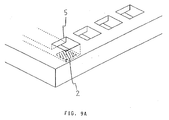
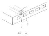
- Figures 9A and 18A are perspective views of recording heads according to embodiments of the present invention.
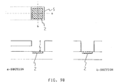
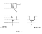
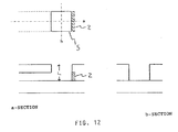
- Figures 9B, 10, 11, 12, 13, 14, 15, 16, 17, 18B, 19 and 20 show the recording heads according to embodiments of the present invention.
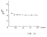
- Figure 21 is a graph of the change of a ratio l a / l b (front and back sides of the bubble).
- Figures 22A and 22B illustrate movement of the leading edge of the bubble per unit time.
- the left side views are top plan views; and the right side views are side views at the corresponding time.
- FIGS 1A and 1B shows typical examples of liquid passages using the present invention.
- the present invention is not limited to these structures, as will be understood from the descriptions which will be made hereinafter.
- a heat generating resistor layer 2 is provided on a unshown base plate, and a plurality of ejection outlets 5 are provided at an edge of the base plate.
- a selecting electrodes E1 and a common electrode E2 have the known structures.
- Designated by reference characters D and C are a protection layer and a common liquid chamber, respectively.
- the temperature of the heat generating portion between the electrodes E1 and E2 instantaneously rises to cause film boiling (not less than 300 o C), by which a bubble 6 is produced.
- the bubble 6 communicates with the ambience at its edge A adjacent the heat generating resistor layer 2 to produce a stabilized liquid droplet (broken line 7). Since the bubble communicates with the ambience (atmospheric air) adjacent the edge of the ejection outlet opening 5, the droplet of the ink can be created without splashing of the liquid and without the production of the mist. The thus produced droplet of the liquid is ejected at deposited on the recording material.
- the recording principle is such that the liquid passage B is not completely blocked by the bubble 6 during the growth thereof. So, the ink refilling after the ejection is effected in good order.
- the accumulated heat by the high temperature (not less than 300 o C) is ejected into the ambience, and therefore, the frequency of the response is increased.
- the common liquid chamber C is not shown.
- the liquid passage B is bent, as contrasted to Figure 1A structure, and the heat generating resistor 2 is provided on the surface of the base plate at the bent portion.
- the ejection outlet has a cross-section decreasing in the direction of the ejection and is faced to a heat generating resistor 2.
- the ejection outlets are formed in an orifice plate OP.
- the film boiling (not less than 300 o C) is caused, by which the bubble 6 develops to displace the ink in the thickness of the orifice plate OP.
- the bubble 6 communicates with the ambience in a region between A1 which is an outside edge of the ejection outlet opening 5 and A2 which is adjacent to the ejection outlet opening. With this state of communication, a stabilized liquid droplet as shown by the broken line 7 can be ejected along the center of the ejection outlet without the splashing of the liquid and without the production of the mist.
- the growth of the bubble does not block the liquid passage. More particularly, as will be understood from Figure 1C, when the bubble communicates with the ambience, the bubble does not completely block the passage.
- the liquid which is going to constitute the droplet in partly connected with the liquid in the liquid passage. This increases the speed of the refilling of the liquid in the passage.
- the connection between the outside liquid and the inside liquid is effective to provide good shape of the droplet as shown in Figure 1B by the reference numeral 7, so that the satellite droplets are formed in a stabilized manner.
- the liquid not required to displace toward the ejection outlet can remain in the liquid passage as the mass of the liquid continuing the other remaining liquid, and therefore, the volume and the speed of the droplet 7 can be stabilized.
- the bubble develops at a high speed toward the ejection outlet using the stabilized film boiling (particularly not less than 300 o C), and therefore, the high speed recording is possible with high stability with the aid of good refilling property of the liquid passage which is not blocked by the bubble.
- the first condition is that the bubble communicates with the ambience under the condition that the internal pressure of the bubble is lower than the ambient pressure.
- the communication under such a condition is preferable since then the instable liquid adjacent the ejection outlet is prevented from scattering, although such liquid is scattered when the condition is not satisfied.
- the second condition is that the bubble communicates with the ambience under the condition that the first order differential of a movement speed of the front edge (the edge adjacent to the ejection outlet) of the bubble is negative.
- the third condition is that the bubble communicates with the ambience under the condition of l ⁇ a / l ⁇ b > 1 , where l a is a distance from an ejection outlet side edge of the ejection energy generating means to the ejection outlet side edge of the bubble, and l b is a distance from that edge of the energy generating means remote from the ejection outlet to that edge of the bubble remote from the ejection outlet. It is further preferable that the second and third conditions are simultaneously satisfied.
- the measuring method of ink volume Vd outside the ejection outlet will be dealt with.
- the configurations of the liquid droplet at the respective times after the ejection are determined by observation through a microscope 32 while the liquid droplet being ejected through the ejection outlet is illuminated with pulse light using a proper light source 31 such as stroboscope, LED or laser. More particularly, the recording head is driven continuously at a constant frequency, and the pulse light is emitted in synchronism with the driving pulse and with a predetermined delay, by which the configuration of the liquid droplet projected in a direction after a predetermined period from the ejection can be determined.
- the pulse width of the pulse light is desirably as small as possible, provided that the quantity of light sufficient for the measurement is assured, since then the measurement is accurate.
- the volume of the droplet can be measured on the basis of measurement in one direction. However, for further accuracy, the following method is desirable.
- the projective configurations of the ejected liquid droplet is observed through the microscope simultaneously in orthogonal directions y and z which are perpendicular to the X-axis, which is the ejection direction of the liquid droplet, while the droplet is illuminated with the pulse light described above.
- the direction y of the measurement through the microscope or the direction z is preferably parallel to the direction of the array of the ejection outlets.
- the widths a (x) and b(x) of the liquid droplet, along the X-axis, of the liquid droplet is measured on the images obtained in the two directions ((a) and (b)).
- the equation is based on approximation of y-z cross-section to an oval shape. The approximation provides sufficiently high accuracy for the calculations for the liquid droplet or the bubble volume which will be described hereinafter.
- the preparation is made for observation of the bubble in the liquid passage, it is illuminated with pulse light in the two directions in the same manner as in the method of measuring the droplet volume, so that the projective configurations are determined. Then, using the above equation, the volume can be determined.
- the required time resolution power is approximately 0.1 micro-sec.
- the pulse light source is in the form of an infrared LED, and the pulse width thereof is approximately 50 msec.
- An infrared camera is connected to the microscope to photograph the image, from which the above-described a(x) and b(x) are determined. Then, the above-described equation is used.
- a gas flow is used to determine which is larger the internal pressure of the bubble or the ambient pressure. This will be described.
- the gas flow motion of the gas
- a fine tuft is disposed adjacent the ejection outlet, and the motion of the tuft caused by the gas flow is observed by the microscope. Otherwise, the change in the density of the air adjacent the ejection outlet caused by the flow is detected through an optical method or the like such as Schlieren method, Mach-Zehnder interferometer method or hologram method or the like.
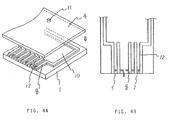
- Figures 4A and 4B are a perspective view of a preferable recording head before the assembling thereof and a top plan view thereof.
- the top plate shown in Figure 4A is omitted.
- the structure of the recording head shown in Figures 4A and 4B will be described. It comprises a base member 1 having walls 8, and a top plate 4 secured on the tops of the walls 8. By the joining, both of the liquid passages 12 and the common liquid chamber 10 are formed.
- the top plate 4 is provided with a supply opening 11 for supplying the ink, and the ink is supplied into the liquid passage 12 through the common liquid chamber 10 to which the liquid passages 12 communicates.
- the base member 1 is provided with heaters 2, and for each of the heaters 2, the liquid passages are formed.
- the heater 2 has a heat generating resistor layer (not shown) and an electrode (not shown) electrically connected with the heat generating resistor layer.
- the heater 2 is energized through the electrode in accordance with the recording signal.
- the heater 2 Upon the energization, the heater 2 generates thermal energy to supply the thermal energy to the ink supplied into the liquid.
- the thermal energy produces a bubble in the ink in accordance with the recording signal.
- FIG. 5A and 5B there is shown a sectional view of the recording head and a top plan view.
- the difference of the recording head from the recording head shown in Figure 5 that the ink supplied into the liquid passage is ejected along or substantially along the liquid passage direction, whereas in Figures 5A and 5B, the ink is ejected at an angle from the ink passage (the ejection outlet is formed directly above the heater).
- the ejection outlets 5 are formed in an orifice plate 16, and it integrally has walls 9 between the ejection outlets 5.
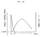
- Figures 6(a), 6(b), 6(c), 6(d) and 6(e) are graphs of bubble internal pressure vs. volume change with time in a first specific liquid jet method and apparatus according to a first specific embodiment of the present invention.
- the volume and the speed of the discharged liquid droplets, so that the splash or mist which is attributable to the incapability of sufficiently high speed record can be suppressed.
- the contamination of the background of images can be prevented.
- the present invention is embodied as an apparatus, the contamination of the apparatus can be prevented.
- the ejection efficiency is improved.
- the clogging of the ejection outlet or the passage can be prevented.
- the service life of the recording head is expanded with high quality of the print.
- the liquid passage is constituted by a base 1, a top plate 4 and an unshown walls.
- Figure 7 shows the initial state in which the passage is filled with ink 3.
- the heater 2 electro-thermal transducer, for example
- the heater 2 is instantaneously supplied with electric current
- the ink adjacent the heater 2 is abruptly heated by the pulse of the current, upon which a bubble 6 is produced on the heater 2 by the so-called film boiling, and the bubble abruptly expands (Figure 7(b)).
- the bubble continues to expand toward the ejection outlet 5, that is, in the direction of low intertia resistance. It further expands beyond the outlet 5 so that it communicates with the ambience (Figure 7(c)).
- the ambience is in equilibrium with the inside of the bubble 6, or it enters the bubble 6.
- the ink 3 pushed out by the bubble through the outlet 5 moves forward further by the momentum given by the expansion of the bubble, until it becomes an independent droplet and is deposited on a recording material 101 such as paper (Figure 7, (d)).
- the cavity produced adjacent the outlet 5 is supplied with the ink from behind by the surface tension of the ink 3 and by the wetting with the member defining the liquid passage, thus restoring the initial state ( Figure 7, (e)).
- the recording medium 101 is fed to the position faced to the ink ejection outlet 5 on a platen by means of the platen, roller, belt or a suitable combination of them.
- the recording material 101 may be fixed, while the outlet (the recording head) is moved, of both of them may be moved to impart relative movement therebetween. What is required in the relative movement therebetween to face the outlet to a desired position of the recording material.
- the bubble is made to communicate with the ambience in the period satisfy t ⁇ t1 in Figure 6, (a).
- the relation between the bubble internal pressure and the bubble volume with the time is as shown in Figure 6, (b), because the ink is ejected by the expansion of the bubble.
- the ejection of the droplet under this condition is preferable to the ejection with the bubble internal pressure higher than the ambient pressure (the gas ejects into the ambience), in that the contamination of the recording paper or the inside of the apparatus due to the ink mist or splash. Additionally, the ink acquires sufficient energy, and therefore, a higher ejection speed, because the bubble communicates with the ambience only after the volume of the bubble increases.
- the lower pressure communication is effective to prevent the unstabilized liquid adjacent the outlet from splashing which otherwise is liable to occur.
- it is advantageous in that the force, if not large, is applied to the unstabilized liquid in the backward direction, by which the liquid ejection is further stabilized, and the unnecessary liquid splash can be suppressed.
- the recording head had the heater 2 adjacent to the outlet 5. This is the easy arrangement to make the bubble communicate with the ambience.
- the above-described preferable condition is not satisfied by simply making the heater 2 close to the outlet.
- the proper selections are made to satisfy it with respect to the amount of the thermal energy (the structure, material, driving conditions, area or the like of the heater, the thermal capacity of a member supporting the heater, or the like), the nature of the ink, the various sizes of the recording head (the distance between the ejection outlet and the heater, the widths and heights of the outlet and the liquid passage).
- the width of the liquid passage is substantially determined by the configuration of the used thermal energy generating element, but it is determined on the basis of rule of thumb. However, it has been found that the configuration of the liquid passage is significantly influential to growth of the bubble, and that it is an effective factor.
- the communicating condition can be controlled by changing the height of the liquid passage.
- the height of the liquid passage is smaller than the width thereof (H ⁇ W).
- the communication between the bubble and the ambience occurs when the bubble volume is not less than 70 %, further preferably, not less than 80 % of the maximum volume of the bubble or the maximum volume which will be reached before the bubble communicates with the ambience.
- the volume V of the bubble is measured from the start of the bubble creation to the communication thereof with the ambience. Then, the second order differential d2V/dt2 is calculated, by which the relation (which is larger) between the internal pressure and the ambient pressure is known, because if d2V/dt2 > 0 , the internal pressure of the bubble is higher than the external pressure, and if d2V/dt2 ⁇ 0 , the internal pressure is equal to or less than the external pressure.
- the bubble can be observed directly or indirectly from the outside.
- a part of the recording head is made of transparent material. Then, the creation, development or the like of the bubble is observed from the outside. If the recording head is of non-transparent material, a top plate or the like of the recording head may be replaced with a transparent plate. For the better replacement from the standpoint of equivalency, the hardness, elasticity and the like are as close as possible with each other.
- top plate of the recording head is made of metal, non-transparent ceramic material or colored ceramic material, it may be replaced with transparent plastic resin material (transparent acrylic resin material) plate, glass plate or the like.
- transparent plastic resin material transparent acrylic resin material
- the material to replace preferably has the wetting nature relative to the ink or another nature which is as close as possible to that of the material. Whether the bubble creation is the same or not may be confirmed by comparing the ejection speeds, the volumes of ejected liquid or the like before and after the replacement. If a suitable part of the recording head is made of transparent material, the replacement is not required.
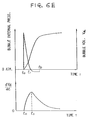
- the volume Vd of the ink is measured, and the second order differential d2Vd/dt2 is obtained. Then, the relation between the internal pressure and the external pressure can be determined. More specifically, if d2Vd/dt2 > 0 , the internal pressure of the bubble is higher than the external pressure, and if d2Vd/dt2 ⁇ 0 , the internal pressure is equal to or less than the external pressure.
- Figure 6, (d) shows the change, with time, of the first order differential dVd/dt of the volume of the ejected ink when the bubble communication occurs with the internal pressure higher than the external pressure.
- the configuration of the droplet at any times after the ejection can be determined on the basis of observation, by a microscope, of the ejecting droplet while it is illuminated with a light source such as stroboscope, LED or laser.
- the pulse light is emitted to the recording head driven at regular intervals, with synchronization therewith and with a predetermined delay. By doing so, the configuration of the bubble as seen in one direction at the time which is the predetermined period after the ejection, is determined.
- the pulse width of the pulse light is preferably as small as possible, provided that the quantity of the light is sufficient for the observation, since then the configuration determination is accurate.
- the bubble communicates with the ambience when the first order differentiation of the movement speed of an ejection outlet side end of the bubble is negative, as shown in Figure 8; and the bubble communicates with the ambience when l ⁇ a / l ⁇ b ⁇ 1 is satisfied where l a is a distance between an ejection outlet side end of the ejection energy generating means and an ejection outlet side end of the bubble, and l b is a distance between that end of the ejection energy generating means which is remote from the ejection outlet and that end of the bubble which is remote from the ejection outlet. It is further preferable that both of the above conditions are satisfied when the bubble communicates with the ambience.
- Figure 7 shows the initial state in which the passage is filled with ink 3.
- the heater 2 electro-thermal transducer, for example
- the heater 2 is instantaneously supplied with electric current
- the ink adjacent the heater 2 is abruptly heated by the pulse of the current in the form of the driving signal from the driving circuit, upon which a bubble 6 is produced on the heater 2 by the so-called film boiling, and the bubble abruptly expands (Figure 7(b)).
- the bubble continues to expand toward the ejection outlet 5 ( Figure 7(c)), that is, in the direction of low intertia resistance. It further expands beyond the outlet 5 so that it communicates with the ambience (Figure 7(d)).
- the bubble 6 communicates with the ambience when l ⁇ a / l ⁇ b ⁇ 1 is satisfied, where l a is a distance from an ejection outlet side end of the heater 2 functioning as the ejection energy generating means and an ejection outlet side end of the bubble 6, and l b is a distance from that end of the heater 2 remote from the ejection outlet and that end of the bubble 6 which is remote from the ejection outlet.
- the ink 3 pushed out by the bubble through the outlet 5 moves forward further by the momentum given by the expansion of the bubble, until it becomes an independent droplet and is deposited on a recording material 101 such as paper (Figure 7, (e)).
- the cavity produced adjacent the outlet 5 is supplied with the ink from behind by the surface tension of the ink 3 and by the wetting with the member defining the liquid passage, thus restoring the initial state ( Figure 7, (f)).
- the recording medium 101 is fed to the position faced to the ink ejection outlet 5 on a platen by means of the platen, roller, belt or a suitable combination of them.
- the recording material 101 may be fixed, while the outlet (the recording head) is moved, or both of them may be moved to impart relative movement therebetween. What is required in the relative movement therebetween to face the outlet to a desired position of the recording material.
- the volume of the liquid ejected through the ejection outlet is constant at all times, since the bubble communicates with the ambience.
- a high quality image can be produced without non-uniformity of the image density.
- the bubble communicates with the ambience under the condition of l ⁇ a / l ⁇ b ⁇ 1 , the kinetic energy of the bubble can be efficiently transmitted to the ink, so that the ejection efficiency is improved.
- the time required for the cavity produced adjacent to the ejection outlet after the liquid is ejected is filled with new ink can be reduced as compared with the liquid (ink) is ejected under the condition of l ⁇ a / l ⁇ b ⁇ 1 , and therefore, the recording speed is further improved.
- the top plate 4 is made of transparent glass plate.
- the recording head is illuminated from the above by a light source capable of pulsewise light emission such as stroboscope, laser or LED.
- the recording head is observed through microscope.
- the pulsewise light source is turned on and off in synchronism with the driving pulses applied to the heater, and the behavior from the creation of the bubble to the ejection of the liquid is observed, using the microscope and camera. Then, the distances l a and l b are determined.
- the width of the liquid passage is substantially determined by the configuration of the used thermal energy generating element, but it is determined on the basis of rule of thumb. However, it has been found that the configuration of the liquid passage is significantly influential to growth of the bubble, and that it is an effective factor for the above condition of the thermal energy generating element in the passage in teh second specific embodiment.
- the growth of the bubble may be controlled so as to satisfy l ⁇ a / l ⁇ b ⁇ 1 , preferably l ⁇ a / l ⁇ b ⁇ 2 , and further preferably l ⁇ a / l ⁇ b ⁇ 4 . It has been found that the liquid passage height H is smaller than at least the liquid passage width W (H ⁇ W), since then the recording operation is less influenced by the ambient condition or another, and therefore, the operation is stabilized.
- the first order differential of the moving speed of the ejection outlet side end of the bubble is negative, when the bubble communicates with the ambience.
- the third specific embodiment provides a solution to the problem solved by the first specific embodiment, by a different method.
- the major problem underlying this third specific embodiment is that the ink existing adjacent the communicating portion between the bubble and the ambience is over-accelerated with the result of the ink existing there is separated from the major part of the ink droplet. If this separation occurs, the ink adjacent thereto is splashed, or is scattered into mist.
- the third specific embodiment is based on the finding that the drawbacks are attributable to the acceleration.
- Figure 8 is graphs of the first order differential and the second order differential (the first order differential of the moving speed) of the displacement of the ejection outlet side end of the bubble from the ejection outlet side end of the heater until the bubble communicates with the ambience. It will be understood that the above discussed problems arise in the case of a curve A in Figure 8, (a) and (b), where the first order differential of the moving speed of the ejection outlet side end of the bubble is positive.
- Curves B in Figure 8, (a) and (b) represent the third specific embodiment using the concept of Figure 7.
- the created bubble communicates with the ambience under the condition that the first order differential of the moving speed of the ejection outlet side end of the bubble. By doing so, the volumes of the liquid droplets are stabilized, so that high quality images can be recorded without ink mist or splash and the resulting paper and apparatus contamination.
- the ejection efficiency is improved so that the clogging of the nozzle can be avoided.
- the droplet ejection speed is increased, so that the ejection direction can be stabilized, and the required clearance between the recording head and the recording paper can be increased so that the designing of the apparatus is made easier.
- the principle and structure arc applicable to a so-called on-demand type recording system and a continuous type recording system.
- the principle is such that at least one driving signal is applied to an electrothermal transducer disposed on a liquid (ink) retaining sheet or liquid passage, the driving signal being enough to provide such a quick temperature rise beyond a departure from nucleation boiling point, by which the thermal energy is provided by the electrothermal transducer to produce film boiling on the heating portion of the recording head, whereby a bubble can be formed in the liquid (ink) corresponding to each of the driving signals.
- the driving signal is preferably in the form of a pulse, because the development and contraction of the bubble can be effected instantaneously, and therefore, the liquid (ink) is ejected with quick response.
- the present invention is effectively applicable to a so-called full-line type recording head having a length corresponding to the maximum recording width.
- a recording head may comprise a single recording head and plural recording head combined to cover the maximum width.
- the present invention is applicable to a serial type recording head wherein the recording head is fixed on the main assembly, to a replaceable chip type recording head which is connected electrically with the main apparatus and can be supplied with the ink when it is mounted in the main assembly, or to a cartridge type recording head having an integral ink container.
- the provisions of the recovery means and/or the auxiliary means for the preliminary operation are preferable, because they can further stabilize the effects of the present invention.
- preliminary heating means which may be the electrothermal transducer, an additional heating element or a combination thereof.
- means for effecting preliminary ejection (not for the recording operation) can stabilize the recording operation.
- the recording head mountable may be a single corresponding to a single color ink, or may be plural corresponding to the plurality of ink materials having different recording color or density.
- the present invention is effectively applicable to an apparatus having at least one of a monochromatic mode mainly with black, a multi-color mode with different color ink materials and/or a full-color mode using the mixture of the colors, which may be an integrally formed recording unit or a combination of plural recording heads.
- a recording head shown in Figure 4 was produced with the following conditions: Top plate 6: glass height and width of the liquid passage 12 of the recording head: 20 microns and 58 microns, respectively width and length of the heater 2: 28 microns and 18 microns Distance from the ejection outlet side edge of the heater to the ejection outlet: 20 microns Density of the liquid passages: 360 per inch Number of liquid passages 12: 48 Contents of the liquid: C.I.
- pulsewise electric signals were applied to the heater 2.
- the voltage of the pulse wave was 9.0 v, and the pulse width was 5.0 micro-sec.
- the frequency was 2 KHz.
- Figure 6 shows the changes, with time, of the volume Vd of the ink ejected through the ejection outlet and the first order differential dVd/dt of the volume Vd of the ink.
- the second order differential d2Vd/dt2 is negative in the period from 0.5 micro-sec after the start of the bubble creation to the communication of the bubble with the ambience approximately 2 micro-sec layer, and therefore, the internal pressure of the bubble is lower than the ambient pressure. This was confirmed with Figure 6.
- the volume of the liquid was within the range of 14 ⁇ 1 p-liter for all of the ejection outlets 5.
- the speeds of the liquid droplets was uniformly about 14 m/sec, and the speed and the uniformity was satisfactory for good recording operation.
- the 16 heaters 2 were supplied with such electric signals as to provide a checker pattern by the respective picture elements.
- the desired checker pattern was printed on the recording paper without non-uniformity.
- the image was enlarged and observed, and it was confirmed that the image was free from scattering of the ink, and therefore, without the foggy background.
- the recording head shown in Figure 5 was used.
- the orifice plate 14 was made of transparent glass.
- the ejection outlets 5 a circle having a diameter of 36 microns at the surface side of the orifice plate.
- the heating conditions for the heater 12 of the recording head was 7.0 V and 4.5 micro-sec at the frequency of 2 KHz.
- the second order differential d2V/dt2 of the volume of the bubble was negative in the period from 0.5 micro-sec after the start of the bubble creation to the communication of the bubble with the ambience approximately 2.1 micro-sec later, and therefore, the bubble internal pressure is lower than the ambient pressure.
- the volumes of the droplets were measured, and was within the range of 18 ⁇ 1 p-liter for all the nozzles.
- the speed of the liquid droplet was approximately 10 m/sec.
- the 16 heaters 2 were supplied with electric signals for formation of the checker pattern by the respective picture elements.
- a desired checker pattern was formed on the recording paper without non-uniformity.
- the checker pattern image was enlarged and observed, and it was confirmed that the image was free from the scattering of the ink and the background fog.
- Embodiment 1 The same recording head as in Embodiment 1 was used.
- the contents of the liquid were: C.I. Direct Black 154: 3.5 % by weight
- Glycerin 5.0 % by weight
- Diethylene glycol 25.0 % by weight
- Polyethylene glycol 28.0 % by weight (average molecular weight was 300)
- Ion exchange water 38.5 % by weight They were stirred in a container into a uniform mixture and was filtered with a Teflon filter having a diameter of 0.45 micron.
- the viscosity was 10.5 cps (20 o C).
- the other conditions were the same as in Embodiment 1.
- the recording head used had bent liquid passages similarly to the recording head used in Embodiment 2.
- the ink used was the same as in Embodiment 2.
- Table 1 shows the results of ejection of the respective recording heads.
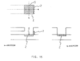
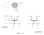
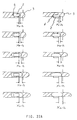
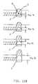
- the structures of the recording heads are shown in Figures 9 - 17.
- FIG. 9 - 17 the structures Of the recording heads will be described.
- Each of these Figures include a top plan view, a sectional view taken along a line a-a and a cross-section taken along b-b to illustrate the configuration and position of the heat generating resistor 2.
- the ejection outlets 5 have the same configuration as the cross-section of the passage from the heater 2 to the ejection outlet. However, as will be understood from Figure 1B, the configuration may be properly selected.
- the heat generating resistor 2 is disposed on the base plate and is smaller than the cross-sectional area of the ejection passage. With this structure, the liquid passage is not blocked so that the action illustrated in Figure 1B is further stabilized.
- Figure 11 has the structure wherein the heat generating resistor 2 is deviated in the other way.
- the heat generating resistor 2 is provided on the above-described end wall, in which the droplet has the configuration which is a mixture of Figure 1A and Figure 1B configurations. This structure is advantageous in the good refilling performance.
- the heat generating resistors 2 are provided on the opposite lateral walls.
- a high ejection speed can be provided by the unification of the two bubbles provided by the respective heat generating resistors 2.
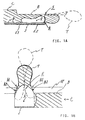
- Figure 14 the structure is a combination of Figure 13 structure and Figure 12 structure, as will be understood from the Figure.
- the number of bubble creating sources is 3.
- Figure 15 shows the structure which is a combination of Figure 1B structure and Figure 12 structure.
- Figure 16 shows the structure which is a combination of Figure 15 structure and Figure 13 structure.
- the recording heads used had straight liquid passages as in the recording head of Embodiment 1.
- the ink used was the same as in Embodiment 1.
- Table 2 shows the result of ejections for the recording heads.
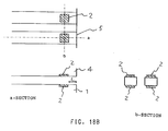
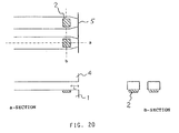
- Figures 18 - 20 show the structure of the recording heads.
- an additional heat generating resistor 2 is provided at a side facing the base plate, in addition to the heat generating resistor 2 on the base plate in the liquid passage. They are simultaneously driven, by which the center of the ejection can be shifted to the center of the ejection outlet. By doing so, the ejection becomes similar to that of Figure 1B.
- Figure 19 shows a structure which has the advantages of Figure 1A and Figure 1B structures, so that a tail of the liquid droplet can be shifted to the center of the ejection.
- the ejection outlet of Figure 1A is converged in the ejection direction.
- the bubble communicates with the ambience under the condition that the internal pressure of the bubble is lower than the external pressure, so that the gas in the bubble is prevented from exploding.
- the background fog on the recording paper or the contamination of the inside of the apparatus attributable to the mist or splash of the ink can be prevented.
- the kinetic energy of the bubble can be sufficiently transmitted to the ink, and therefore, the ejection efficiency is improved.
- the recording head shown in Figure 4 was used with the following conditions: Top plate 4: glass Height, width and length of the liquid passage 12: 25 microns, 35 microns and 195 microns Width and length of the heater: 30 microns and 25 microns Distance from the ejection outlet side edge of the heater to the ejection outlet: 20 microns Density of the liquid passages and ejection outlets: 360 per inch Number of ejection outlets: 48
- the contents of the liquid were as follows: C.I.
- the heating conditions by the heater 2 were 9.0 V and 5.0 micro-sec at the frequency of 4 KHz.
- the 16 heaters 2 were supplied with such electric signals as to provide a checker pattern by the respective picture elements. It was confirmed that a desired checker pattern was formed on the recording paper without non-uniformity of the print. The image was enlarged and observed, and it was confirmed that the image was free from the ink scattering and the background fog.
- the recording head used in Embodiment 1 for the third condition ( Figure 4) was used.
- the contents of the liquid were: C.I. Direct Black 154: 3.5 % by weight
- Glycerin 5.0 % by weight
- Diethylene glycol 25.0 % by weight
- Polyethylene glycol 28.0 % by weight (average molecular weight was 300)
- Ion exchange water 38.5 % by weight They were stirred in a container into a uniform mixture and were filtered with a Teflon filter having an aperture diameter of 0.45 micron.
- the viscosity was 10.5 cps (20 o C).
- the ink was supplied and ejected.
- Embodiment 1 As a result, it was confirmed that the ejection speed is lower than in Embodiment 1, more particularly, 7.5 msec. However, the ejections were very stable.
- the kinetic energy of the bubble can be sufficiently transmitted to the ink, and therefore, the ejection efficiency is increased, by which the contamination of the background on the recording paper and the contamination of the inside Of the apparatus due to the mist and/or the splash can be prevented, and in addition, the clogging of the nozzles can be prevented.
- the time required for the cavity adjacent the ejection outlet after the ejection of the liquid droplet to be filled with the new ink can be reduced, so that the speed of the recording is further increased.
- the ejection speed is increased, the direction of the droplet ejection is stabilized, so that the distance between the recording head and the recording paper may be increased, thus making the designing of the recording head easier.
- the second condition is that the first order differential of the movement speed of the ejection side end of the bubble is negative (the acceleration speed is not positive), the ink adjacent to the communicating part is not imparted with an extremely high acceleration, and therefore, the ink adjacent the communicating part is not splashed or pulverized into mist, but the ink is unified with the main droplet, and therefore, the background contamination of the record and the contamination of the inside of the apparatus can be prevented.
- the kinetic energy of the bubble can be sufficiently transferred to the ink, and therefore, the ejection efficiency is improved.
- the bubble since the bubble communicates with the ambience after the bubble volume is increased, and therefore, almost all of the ink adjacent to the ejection outlet is able to communicate with the ambience, so that the ejection volume can be stabilized.
- the ink does not remain adjacent the ejection outlet, and therefore, the possible ejection failure attributable to the introduction of the air into the ink in the liquid passage, can be avoided.
- the position of the ejection outlet side end of the bubble at the respective times after the start of the bubble creation can be observed by a microscope wherein the bubble is illuminated from the top or side with pulse light such as stroboscope (LED) or laser. More particularly, as shown in Figures 22A and 22B, wherein the ejection process is shown, the change, with time, of the displacement x b-h of the ejection outlet side end of the bubble from the ejection side end of the heater from the start of the bubble creation to the communication of the bubble with the ambience.
- a first order differential dx b-h /dt of the displacement is obtained, by which the moving speed vx of the ejection outlet side end of the bubble is obtained.
- the first order differential dvx/dt of the moving speed (the second order differential d2x b-h /d2t of the displacement) can be obtained.
- the bubble can be observed directly or indirectly from the outside.
- a part of the recording head is made of transparent material. Then, the creation, development or the like of the bubble is observed from the outside. If the recording head is of non-transparent material, a top plate or the like of the recording head may be replaced with a transparent plate. For the better replacement from the standpoint of equivalency, the hardness, elasticity and the like are preferably as close as possible with each other.
- the plate of the recording head is made of metal, non-transparent ceramic material or colored ceramic material, it may be replaced with transparent plastic resin material (transparent acrylic resin material) plate, glass plate or the like.
- transparent plastic resin material transparent acrylic resin material
- the part of recording head to be replaced and the material to replace are not limited to the described above.
- the material to replace preferably has the wetting nature relative to the ink or another nature which is as close as possible to that of the material. Whether the bubble creation is the same or not may be confirmed by comparing the ejection speeds, the volumes of the ejected liquid or the like before and after the replacement. If a suitable part of the recording head is made of transparent material, the replacement is not required.
- the recording head as shown in Figure 4 was used with the following conditions: Top plate: glass Height and width of the liquid passage 12: 25 microns and 35 microns Width and length of the heater: 30 microns and 25 microns A distance from the ejection outlet side end of the heater to the ejection outlet: 25 microns Density of the liquid passages and ejection outlets: 360 per inch Number of ejection outlets: 48
- the contents of the ink were as follows: C.I.
- the heating conditions of the heater 2 of the recording head were 9.0 V and 5 micro-sec at the frequency of 2 KHz.
- the ejections of the ink through consecutive 16 nozzles were observed by a microscope using a pulse light source. It was confirmed that the bubble communicates with the ambience approximately 2 micro-sec after the start of the bubble creation. The displacement of the ejection outlet side end of the bubble from the ejection outlet side end of the heater was measured from the start of the bubble creation to the communication of the bubble with the ambience, and it was confirmed that the first order differential of the moving speed of the ejection outlet side end of the bubble is negative.
- the volume of the ejected liquid droplet was 18 ⁇ 1 p-liter for each of the nozzles.
- the speed of the droplet was approximately 9 m/sec.
- the 16 heaters 2 were supplied with such electric signals as to provide a checker pattern by respective picture elements. A desired checker pattern was uniformly formed on the recording paper. The image was enlarged and observed, and it was confirmed that the ink scattering and the background fog were smaller than the conventional head.
- the recording head shown in Figure 5 was used in this embodiment with the following conditions: Ejection outlet circle of diameter: 32 microns Heater size: 22x22 microns Distance from the heater surface to the ejection outlet: 25 microns Density of the liquid passages and ejection outlets: 360 per inch Number of ejection outlets: 48 The same ink as in Embodiment 1 for the second condition was used.
- the heating conditions by the heater 2 of the recording head were 9.0 V and 5 micro-sec at the frequency of 2 KHz.
- the ejections through the consecutive 16 nozzles were observed using a microscope and a pulse light source. It was confirmed that the bubble communicates with the ambience approximately after 3 micro-sec from the start of bubble creation. The displacement of the outlet side end of the bubble from the outlet side end of the heater was measured from the start of the bubble creation and the communication of the bubble with the ambience. It was confirmed that the first order differential of the moving speed of the outlet side end of the bubble is negative.
- the volume of the independent droplet was 17 ⁇ 1 p-liter for each of the nozzles. The speed of the droplet was approximately 7 m/sec.
- the 16 heaters 2 were supplied with such electric signals as to provide a checker pattern by the respective picture elements. It was confirmed that a desired checker pattern was formed on the recording paper without non-uniformity of the print. The image was enlarged and observed, and it was confirmed that the image was free from the ink scattering and the background fog.
- the recording head used in this embodiment was the same as the recording head used in Embodiment 1 for the second condition ( Figure 4).
- the contents of the ink were as follows: C.I. Direct Black 154: 3.5 % by weight Glycerin: 5.0 % by weight Diethylene glycol: 25.0 % by weight Polyethylene glycol: 28.0 % by weight (average molecular weight was 300) Ion exchange water: 38.5 % by weight They were stirred in a container into a uniform mixture and was filtered with a Teflon filter having an aperture diameter of 0.45 micron. The viscosity was 10.5 cps (20 o C). As a result, the ejection speed was lower than that of Embodiment 1 for the second condition, and was 6 m/sec. However, it was confirmed that the ejections were stable.
- the kinetic energy of the bubble can be sufficiently transmitted to the ink, and therefore, the ejection efficiency is improved.
- the clogging of the liquid passage can be prevented.
- the ejection speed of the liquid droplet is increased, so that the direction of the ejection of the droplet can be stabilized. This permits increase of the distance between the recording head and the recording paper, so that the designing of the apparatus is made easier.
- the ambience communication type recording head or apparatus is made practical in the field of the recording apparatus industries.
- the heat generating resistor has been used, the present invention is applicable to the system in which the film boiling is produced by the light energy or to a system wherein the film boiling is produced by a converter which converts light energy or electromagnetic wave to thermal energy.
Landscapes
- Geometry (AREA)
- Physics & Mathematics (AREA)
- Particle Formation And Scattering Control In Inkjet Printers (AREA)
- Ink Jet (AREA)
- Vehicle Body Suspensions (AREA)
- Special Spraying Apparatus (AREA)
- Sewing Machines And Sewing (AREA)
- Degasification And Air Bubble Elimination (AREA)
- Electronic Switches (AREA)
- Steering Control In Accordance With Driving Conditions (AREA)
- Application Of Or Painting With Fluid Materials (AREA)
- Manufacturing Of Electric Cables (AREA)
- Transition And Organic Metals Composition Catalysts For Addition Polymerization (AREA)
Claims (5)
- Un procédé pour évacuer un liquide pour une opération d'enregistrement, comprenant les étapes suivantes :
on forme un passage de liquide mettant en communication un liquide et un orifice d'éjection,
on fournit au liquide de la chaleur produite par un élément de génération d'énergie d'éjection,
on crée une bulle dans le liquide, par la chaleur, de façon que du liquide soit éjecté à travers l'orifice d'éjection, dans des conditions dans lesquelles lorsque le liquide est éjecté, la bulle communique avec l'ambiance,
caractérisé en ce que
une dérivée première de la vitesse de déplacement d'une extrémité de la bulle créée, du côté de l'orifice d'éjection, est non positive, lorsque la bulle qui est créée par les moyens de génération d'énergie d'éjection communique avec l'ambiance à travers l'orifice d'éjection. - Un procédé selon la revendication 1, dans lequel le passage de liquide n'est pas obturé lorsque la bulle communique avec l'ambiance.
- Un procédé selon la revendication 1, dans lequel, dans l'étape de communication, la bulle communique avec l'ambiance dans la condition dans laquelle la pression interne de la bulle est inférieure à la pression de l'ambiance.
- Un procédé selon la revendication 1, dans lequel l'énergie thermique est fournie par des moyens de génération d'énergie thermique, et dans lequel la bulle communique avec l'ambiance lorsqu'est satisfaite la relation

- Un appareil à jet de liquide comprenant une tête d'enregistrement ayant un orifice d'éjection pour éjecter de l'encre, un passage de liquide communiquant avec l'orifice d'éjection et un élément de génération d'énergie d'éjection pour produire de l'énergie thermique pouvant contribuer à l'éjection de l'encre par la création d'une bulle dans le passage de liquide, caractérisé par un circuit d'attaque destiné à appliquer un signal aux moyens de génération d'énergie d'éjection, de façon qu'une dérivée première d'une vitesse de déplacement d'une extrémité de la bulle créée, du côté de l'orifice d'éjection, soit négative, lorsque la bulle qui est créée par les moyens de génération d'énergie d'éjection communique avec l'ambiance à travers l'orifice d'éjection, et par une plaque pour supporter une matière d'enregistrement qui est destinée à recevoir le liquide éjecté.
Priority Applications (1)
| Application Number | Priority Date | Filing Date | Title |
|---|---|---|---|
| EP94117955A EP0641654B1 (fr) | 1990-04-27 | 1991-04-26 | Méthode et appareil d'enregistrement |
Applications Claiming Priority (8)
| Application Number | Priority Date | Filing Date | Title |
|---|---|---|---|
| JP2112832A JP2783647B2 (ja) | 1990-04-27 | 1990-04-27 | 液体噴射方法および該方法を用いた記録装置 |
| JP112834/90 | 1990-04-27 | ||
| JP112832/90 | 1990-04-27 | ||
| JP11283490A JPH0410942A (ja) | 1990-04-27 | 1990-04-27 | 液体噴射方法および該方法を用いた記録装置 |
| JP2112833A JPH0410941A (ja) | 1990-04-27 | 1990-04-27 | 液滴噴射方法及び該方法を用いた記録装置 |
| JP112833/90 | 1990-04-27 | ||
| JP2114472A JPH0412859A (ja) | 1990-04-28 | 1990-04-28 | 液体噴射方法、該方法を用いた記録ヘッド及び該方法を用いた記録装置 |
| JP114472/90 | 1990-04-28 |
Related Child Applications (1)
| Application Number | Title | Priority Date | Filing Date |
|---|---|---|---|
| EP94117955.8 Division-Into | 1991-04-26 |
Publications (3)
| Publication Number | Publication Date |
|---|---|
| EP0454155A2 EP0454155A2 (fr) | 1991-10-30 |
| EP0454155A3 EP0454155A3 (en) | 1992-02-26 |
| EP0454155B1 true EP0454155B1 (fr) | 1995-07-05 |
Family
ID=27470031
Family Applications (2)
| Application Number | Title | Priority Date | Filing Date |
|---|---|---|---|
| EP94117955A Expired - Lifetime EP0641654B1 (fr) | 1990-04-27 | 1991-04-26 | Méthode et appareil d'enregistrement |
| EP91106821A Expired - Lifetime EP0454155B1 (fr) | 1990-04-27 | 1991-04-26 | Méthode et appareil d'enregistrement |
Family Applications Before (1)
| Application Number | Title | Priority Date | Filing Date |
|---|---|---|---|
| EP94117955A Expired - Lifetime EP0641654B1 (fr) | 1990-04-27 | 1991-04-26 | Méthode et appareil d'enregistrement |
Country Status (5)
| Country | Link |
|---|---|
| US (2) | US6155673A (fr) |
| EP (2) | EP0641654B1 (fr) |
| AT (2) | ATE155741T1 (fr) |
| DE (2) | DE69126996T2 (fr) |
| ES (2) | ES2105472T3 (fr) |
Cited By (1)
| Publication number | Priority date | Publication date | Assignee | Title |
|---|---|---|---|---|
| WO2004048100A1 (fr) * | 2002-11-23 | 2004-06-10 | Silverbrook Research Pty Ltd | Tete d'impression pour jet d'encre thermique pourvue d'un systeme d'autorefroidissement |
Families Citing this family (63)
| Publication number | Priority date | Publication date | Assignee | Title |
|---|---|---|---|---|
| DE69120628T2 (de) * | 1990-09-29 | 1996-12-19 | Canon Kk | Verfahren und Vorrichtung zur Tintenstrahlaufzeichnung |
| DE69333236T2 (de) * | 1992-06-29 | 2004-08-05 | Hewlett-Packard Co. (N.D.Ges.D.Staates Delaware), Palo Alto | Dünnschichtwiderstandsdruckkopf für Thermo-Tintenstrahldrucker |
| JPH07178911A (ja) * | 1993-12-22 | 1995-07-18 | Canon Inc | 記録ヘッド用基体及び記録ヘッド |
| DE69515823T2 (de) * | 1994-12-20 | 2000-10-12 | Canon Kk | Tintenstrahlaufzeichnungsverfahren und -gerät |
| US6113221A (en) * | 1996-02-07 | 2000-09-05 | Hewlett-Packard Company | Method and apparatus for ink chamber evacuation |
| CA2208153C (fr) | 1996-06-20 | 2002-07-16 | Canon Kabushiki Kaisha | Methode et appareil pour vider un liquide par une bulle d'air regulariser par un membre mobile pour communiquer avec l'atmosphere |
| AU774891B2 (en) * | 1996-06-20 | 2004-07-08 | Canon Kabushiki Kaisha | Method for discharing liquid by communicating bubble with atmosphere, liquid discharging head for carrying out such method, and recording apparatus |
| JPH1016228A (ja) * | 1996-07-02 | 1998-01-20 | Canon Inc | インクジェットプリント装置および該装置用プリントヘッドの保温制御方法 |
| ES2203740T3 (es) * | 1996-07-31 | 2004-04-16 | Canon Kabushiki Kaisha | Cabezal de chorros de burbujas y aparato para chorros de burbujas que utiliza el mismo. |
| JP3957851B2 (ja) | 1997-12-26 | 2007-08-15 | キヤノン株式会社 | 液体吐出方法 |
| AU2003204459B2 (en) * | 1997-12-26 | 2006-11-02 | Canon Kabushiki Kaisha | Liquid Ejection Method |
| US6350016B1 (en) | 1998-02-10 | 2002-02-26 | Canon Kabushiki Kaisha | Liquid ejecting method and liquid ejecting head |
| JPH11291500A (ja) * | 1998-02-10 | 1999-10-26 | Canon Inc | 液体吐出方法および液体吐出ヘッド |
| EP0953445B1 (fr) * | 1998-04-28 | 2005-03-09 | Canon Kabushiki Kaisha | Méthode d'éjection de liquide |
| DE69931875T2 (de) | 1998-11-12 | 2007-06-06 | Seiko Epson Corp. | Tintenstrahlaufzeichnungsgerät |
| US6474763B1 (en) | 1999-03-01 | 2002-11-05 | Canon Kabushiki Kaisha | Liquid-discharge control method, and liquid discharging apparatus |
| JP3679668B2 (ja) | 1999-12-20 | 2005-08-03 | キヤノン株式会社 | インクジェット記録ヘッドの製造方法 |
| US6706105B2 (en) | 2000-09-29 | 2004-03-16 | Canon Kabushiki Kaisha | Aqueous ink, ink-jet recording method, recording unit, ink cartridge, ink set, and ink-jet recording apparatus |
| US6848769B2 (en) | 2001-06-20 | 2005-02-01 | Canon Kabushiki Kaisha | Liquid ejecting head having a plurality of groups of ejection openings, and image-forming device using the same |
| US6679576B2 (en) * | 2001-07-17 | 2004-01-20 | Hewlett-Packard Development Company, L.P. | Fluid ejection device and method of operating |
| ES2314014T3 (es) * | 2001-08-31 | 2009-03-16 | Canon Kabushiki Kaisha | Cabezal para la inyeccion de liquidos y aparato para la formacion de imagenes que lo utiliza. |
| JP4731763B2 (ja) | 2001-09-12 | 2011-07-27 | キヤノン株式会社 | 液体噴射記録ヘッドおよびその製造方法 |
| US6854820B2 (en) | 2001-09-26 | 2005-02-15 | Canon Kabushiki Kaisha | Method for ejecting liquid, liquid ejection head and image-forming apparatus using the same |
| US6908563B2 (en) * | 2001-11-27 | 2005-06-21 | Canon Kabushiki Kaisha | Ink-jet head, and method for manufacturing the same |
| US6986982B2 (en) * | 2002-02-20 | 2006-01-17 | Canon Kabushiki Kaisha | Resist material and method of manufacturing inkjet recording head using the same |
| JP2003300323A (ja) | 2002-04-11 | 2003-10-21 | Canon Inc | インクジェットヘッド及びその製造方法 |
| JP3950730B2 (ja) | 2002-04-23 | 2007-08-01 | キヤノン株式会社 | インクジェット記録ヘッドおよびインク吐出方法 |
| JP3697228B2 (ja) * | 2002-07-08 | 2005-09-21 | キヤノン株式会社 | 記録装置 |
| JP3862625B2 (ja) * | 2002-07-10 | 2006-12-27 | キヤノン株式会社 | 液体吐出ヘッドの製造方法 |
| JP3890268B2 (ja) * | 2002-07-10 | 2007-03-07 | キヤノン株式会社 | 液体吐出ヘッドおよび、該ヘッドの製造方法 |
| JP3862624B2 (ja) * | 2002-07-10 | 2006-12-27 | キヤノン株式会社 | 液体吐出ヘッドおよび、該ヘッドの製造方法 |
| JP3891561B2 (ja) * | 2002-07-24 | 2007-03-14 | キヤノン株式会社 | インクジェット記録ヘッド |
| US7147306B2 (en) * | 2002-11-23 | 2006-12-12 | Silverbrook Research Pty Ltd | Printhead nozzle with reduced ink inertia and viscous drag |
| US6692108B1 (en) * | 2002-11-23 | 2004-02-17 | Silverbrook Research Pty Ltd. | High efficiency thermal ink jet printhead |
| US6755509B2 (en) * | 2002-11-23 | 2004-06-29 | Silverbrook Research Pty Ltd | Thermal ink jet printhead with suspended beam heater |
| US6820967B2 (en) * | 2002-11-23 | 2004-11-23 | Silverbrook Research Pty Ltd | Thermal ink jet printhead with heaters formed from low atomic number elements |
| US6863381B2 (en) * | 2002-12-30 | 2005-03-08 | Lexmark International, Inc. | Inkjet printhead heater chip with asymmetric ink vias |
| ATE551195T1 (de) * | 2003-07-22 | 2012-04-15 | Canon Kk | Tintenstrahlkopf und dazugehöriges herstellungsverfahren |
| JP4522086B2 (ja) * | 2003-12-15 | 2010-08-11 | キヤノン株式会社 | 梁、梁の製造方法、梁を備えたインクジェット記録ヘッド、および該インクジェット記録ヘッドの製造方法 |
| US20050145715A1 (en) * | 2003-12-31 | 2005-07-07 | Koegler John M.Iii | Drop ejector for ejecting discrete drops of liquid |
| JP4981260B2 (ja) * | 2004-03-16 | 2012-07-18 | キヤノン株式会社 | 水性インク、反応液と水性インクのセット及び画像形成方法 |
| US7625080B2 (en) * | 2004-06-18 | 2009-12-01 | Hewlett-Packard Development Company, L.P. | Air management in a fluid ejection device |
| TWI286517B (en) | 2004-06-28 | 2007-09-11 | Canon Kk | Method for manufacturing minute structure, method for manufacturing liquid discharge head, and liquid discharge head |
| CN100546720C (zh) * | 2004-07-02 | 2009-10-07 | 三井化学株式会社 | 改性离子交换树脂和双酚类的制造方法 |
| US7101025B2 (en) | 2004-07-06 | 2006-09-05 | Silverbrook Research Pty Ltd | Printhead integrated circuit having heater elements with high surface area |
| JP4804360B2 (ja) * | 2004-11-02 | 2011-11-02 | キヤノン株式会社 | 蛍光画像形成方法及びその画像 |
| JP4459037B2 (ja) * | 2004-12-01 | 2010-04-28 | キヤノン株式会社 | 液体吐出ヘッド |
| JP4614383B2 (ja) * | 2004-12-09 | 2011-01-19 | キヤノン株式会社 | インクジェット記録ヘッドの製造方法、及びインクジェット記録ヘッド |
| JP4553360B2 (ja) * | 2004-12-24 | 2010-09-29 | キヤノン株式会社 | インクジェット記録ヘッド |
| JP4641440B2 (ja) * | 2005-03-23 | 2011-03-02 | キヤノン株式会社 | インクジェット記録ヘッドおよび該インクジェット記録ヘッドの製造方法 |
| JP4693496B2 (ja) * | 2005-05-24 | 2011-06-01 | キヤノン株式会社 | 液体吐出ヘッドおよびその製造方法 |
| US9944074B2 (en) * | 2006-08-15 | 2018-04-17 | Hewlett-Packard Development Company, L.P. | System and method for creating a pico-fluidic inkjet |
| US7832843B2 (en) * | 2006-08-28 | 2010-11-16 | Canon Kabushiki Kaisha | Liquid jet head |
| JP5037903B2 (ja) * | 2006-11-09 | 2012-10-03 | キヤノン株式会社 | インクジェット記録ヘッドおよびインクジェット記録装置 |
| JP5317423B2 (ja) * | 2007-03-23 | 2013-10-16 | キヤノン株式会社 | 液体吐出方法 |
| US20090030095A1 (en) * | 2007-07-24 | 2009-01-29 | Laverdure Kenneth S | Polystyrene compositions and methods of making and using same |
| JP5264123B2 (ja) * | 2007-08-31 | 2013-08-14 | キヤノン株式会社 | 液体吐出ヘッド |
| JP4978463B2 (ja) * | 2007-12-28 | 2012-07-18 | ブラザー工業株式会社 | 液体吐出装置 |
| JP2010000649A (ja) | 2008-06-19 | 2010-01-07 | Canon Inc | 記録ヘッド |
| CN102741749B (zh) | 2010-02-05 | 2014-10-08 | 佳能株式会社 | 负型感光性树脂组合物、图案形成方法和液体排出头 |
| RU2526258C2 (ru) | 2010-02-05 | 2014-08-20 | Кэнон Кабусики Кайся | Светочувствительная полимерная композиция, способы получения структуры и головка для подачи жидкости |
| US8794745B2 (en) | 2011-02-09 | 2014-08-05 | Canon Kabushiki Kaisha | Liquid ejection head and liquid ejection method |
| JP2017061102A (ja) | 2015-09-25 | 2017-03-30 | キヤノン株式会社 | 液体吐出ヘッドおよびインクジェット記録装置 |
Family Cites Families (23)
| Publication number | Priority date | Publication date | Assignee | Title |
|---|---|---|---|---|
| CA1127227A (fr) * | 1977-10-03 | 1982-07-06 | Ichiro Endo | Procede d'enregistrement a jet liquide et appareil d'enregistrement |
| JPS54161935A (en) * | 1978-06-12 | 1979-12-22 | Seiko Epson Corp | Ink jet printer |
| US4330787A (en) * | 1978-10-31 | 1982-05-18 | Canon Kabushiki Kaisha | Liquid jet recording device |
| US4345262A (en) * | 1979-02-19 | 1982-08-17 | Canon Kabushiki Kaisha | Ink jet recording method |
| US4334234A (en) * | 1979-04-02 | 1982-06-08 | Canon Kabushiki Kaisha | Liquid droplet forming apparatus |
| US5204689A (en) * | 1979-04-02 | 1993-04-20 | Canon Kabushiki Kaisha | Ink jet recording head formed by cutting process |
| JPS55132291A (en) * | 1979-04-02 | 1980-10-14 | Canon Inc | Recording device |
| US4313124A (en) * | 1979-05-18 | 1982-01-26 | Canon Kabushiki Kaisha | Liquid jet recording process and liquid jet recording head |
| JPS5627354A (en) * | 1979-08-10 | 1981-03-17 | Canon Inc | Recording method by liquid injection |
| JPS56139970A (en) * | 1980-04-01 | 1981-10-31 | Canon Inc | Formation of droplet |
| US4338611A (en) * | 1980-09-12 | 1982-07-06 | Canon Kabushiki Kaisha | Liquid jet recording head |
| JPS61185455A (ja) * | 1985-02-14 | 1986-08-19 | Olympus Optical Co Ltd | インクジエツトプリンタ |
| JPS61197246A (ja) * | 1985-02-28 | 1986-09-01 | Toshiba Corp | 記録装置 |
| JPS61249768A (ja) * | 1985-04-30 | 1986-11-06 | Olympus Optical Co Ltd | インクジエツト記録装置 |
| US4638337A (en) * | 1985-08-02 | 1987-01-20 | Xerox Corporation | Thermal ink jet printhead |
| JPS62119042A (ja) * | 1985-11-20 | 1987-05-30 | Toshiba Corp | 記録装置 |
| CA1303904C (fr) * | 1987-08-10 | 1992-06-23 | Winthrop D. Childers | Formation de gouttelettes au moyen d'une buse decalee |
| JPH0684075B2 (ja) * | 1988-01-29 | 1994-10-26 | 株式会社リコー | 液体噴射記録ヘッド |
| JP2651189B2 (ja) * | 1988-04-08 | 1997-09-10 | 株式会社リコー | 液体噴射記録方法 |
| JP2642670B2 (ja) * | 1988-06-21 | 1997-08-20 | キヤノン株式会社 | インクジェット記録ヘッドの製造方法 |
| JPH0262242A (ja) | 1988-08-29 | 1990-03-02 | Alps Electric Co Ltd | インクジェット式記録方法 |
| JPH0412859A (ja) | 1990-04-28 | 1992-01-17 | Canon Inc | 液体噴射方法、該方法を用いた記録ヘッド及び該方法を用いた記録装置 |
| DE69120628T2 (de) | 1990-09-29 | 1996-12-19 | Canon Kk | Verfahren und Vorrichtung zur Tintenstrahlaufzeichnung |
-
1991
- 1991-04-26 AT AT94117955T patent/ATE155741T1/de not_active IP Right Cessation
- 1991-04-26 ES ES94117955T patent/ES2105472T3/es not_active Expired - Lifetime
- 1991-04-26 ES ES91106821T patent/ES2073614T3/es not_active Expired - Lifetime
- 1991-04-26 EP EP94117955A patent/EP0641654B1/fr not_active Expired - Lifetime
- 1991-04-26 AT AT91106821T patent/ATE124654T1/de not_active IP Right Cessation
- 1991-04-26 DE DE69126996T patent/DE69126996T2/de not_active Expired - Lifetime
- 1991-04-26 DE DE69110958T patent/DE69110958T2/de not_active Expired - Lifetime
- 1991-04-26 EP EP91106821A patent/EP0454155B1/fr not_active Expired - Lifetime
-
1993
- 1993-07-30 US US08/099,396 patent/US6155673A/en not_active Expired - Fee Related
-
2000
- 2000-07-13 US US09/615,933 patent/US6488364B1/en not_active Expired - Fee Related
Cited By (3)
| Publication number | Priority date | Publication date | Assignee | Title |
|---|---|---|---|---|
| WO2004048100A1 (fr) * | 2002-11-23 | 2004-06-10 | Silverbrook Research Pty Ltd | Tete d'impression pour jet d'encre thermique pourvue d'un systeme d'autorefroidissement |
| CN100386207C (zh) * | 2002-11-23 | 2008-05-07 | 西尔弗布鲁克研究有限公司 | 自冷却热喷墨打印头 |
| US7407271B2 (en) | 2002-11-23 | 2008-08-05 | Silverbrook Research Pty Ltd | Self-cooling thermal ink jet printhead |
Also Published As
| Publication number | Publication date |
|---|---|
| EP0641654B1 (fr) | 1997-07-23 |
| DE69110958T2 (de) | 1995-11-30 |
| DE69126996T2 (de) | 1998-02-19 |
| EP0641654A3 (fr) | 1995-04-05 |
| ATE155741T1 (de) | 1997-08-15 |
| EP0454155A3 (en) | 1992-02-26 |
| EP0454155A2 (fr) | 1991-10-30 |
| ES2073614T3 (es) | 1995-08-16 |
| ATE124654T1 (de) | 1995-07-15 |
| ES2105472T3 (es) | 1997-10-16 |
| US6488364B1 (en) | 2002-12-03 |
| DE69110958D1 (de) | 1995-08-10 |
| EP0641654A2 (fr) | 1995-03-08 |
| DE69126996D1 (de) | 1997-09-04 |
| US6155673A (en) | 2000-12-05 |
Similar Documents
| Publication | Publication Date | Title |
|---|---|---|
| EP0454155B1 (fr) | Méthode et appareil d'enregistrement | |
| EP0455167B1 (fr) | Procédé d'éjection d'un liquide, tête d'enregistrement et appareil utilisant le procédé | |
| EP0192428B1 (fr) | Imprimante à jet d'encre thermique avec éjection de gouttelettes produite par effondrement de bulles | |
| EP1184183A2 (fr) | Tête et appareil d'enregistrement à jet d'encre | |
| JPS62263062A (ja) | インクジエツトプリンタ用プリンタヘツド | |
| JPH0410940A (ja) | 液体噴射方法および該方法を用いた記録装置 | |
| JPH0410942A (ja) | 液体噴射方法および該方法を用いた記録装置 | |
| US6467882B2 (en) | Liquid jet recording method and apparatus and recording head therefor | |
| JP2962880B2 (ja) | 液体噴射記録方法、液体噴射記録ヘッド及び記録装置 | |
| US5485186A (en) | Ink jet recording apparatus with efficient and reliable ink supply | |
| JPH01247168A (ja) | インクジェットヘッド | |
| JP3165717B2 (ja) | インク滴噴射記録ヘッド及びそれを用いる記録方法 | |
| US6203142B1 (en) | Liquid jet recording method and apparatus and recording head therefor | |
| JPH07195697A (ja) | インクジェット記録ヘッド,インクジェット記録方法およびインクジェット記録装置 | |
| JP3118039B2 (ja) | インク滴噴射記録ヘッド及びそれを用いる記録方法 | |
| JP3118038B2 (ja) | 液滴噴射記録方法 | |
| JP2952091B2 (ja) | インク滴噴射記録方法及び記録ヘッド | |
| JP2807462B2 (ja) | 液体噴射記録方法 | |
| JP3039710B2 (ja) | インク滴噴射記録方法及び記録ヘッド | |
| JP2962900B2 (ja) | インク滴噴射記録方法及び記録ヘッド | |
| JP3082974B2 (ja) | 液滴噴射記録方法 | |
| JP2005178124A (ja) | 液滴吐出ヘッド及び、液滴吐出ヘッドを備える液滴吐出装置 | |
| JPH05116311A (ja) | インク滴噴射記録方法 | |
| JPH05116316A (ja) | インク滴噴射記録ヘツド及びそれを用いる記録方法 | |
| JPH11997A (ja) | インクジェットヘッド |
Legal Events
| Date | Code | Title | Description |
|---|---|---|---|
| PUAI | Public reference made under article 153(3) epc to a published international application that has entered the european phase |
Free format text: ORIGINAL CODE: 0009012 |
|
| 17P | Request for examination filed |
Effective date: 19910524 |
|
| AK | Designated contracting states |
Kind code of ref document: A2 Designated state(s): AT BE CH DE DK ES FR GB GR IT LI LU NL SE |
|
| PUAL | Search report despatched |
Free format text: ORIGINAL CODE: 0009013 |
|
| AK | Designated contracting states |
Kind code of ref document: A3 Designated state(s): AT BE CH DE DK ES FR GB GR IT LI LU NL SE |
|
| 17Q | First examination report despatched |
Effective date: 19931109 |
|
| GRAA | (expected) grant |
Free format text: ORIGINAL CODE: 0009210 |
|
| AK | Designated contracting states |
Kind code of ref document: B1 Designated state(s): AT BE CH DE DK ES FR GB GR IT LI LU NL SE |
|
| PG25 | Lapsed in a contracting state [announced via postgrant information from national office to epo] |
Ref country code: DK Effective date: 19950705 Ref country code: GR Free format text: LAPSE BECAUSE OF FAILURE TO SUBMIT A TRANSLATION OF THE DESCRIPTION OR TO PAY THE FEE WITHIN THE PRESCRIBED TIME-LIMIT Effective date: 19950705 Ref country code: CH Effective date: 19950705 Ref country code: BE Effective date: 19950705 Ref country code: LI Effective date: 19950705 Ref country code: AT Effective date: 19950705 |
|
| REF | Corresponds to: |
Ref document number: 124654 Country of ref document: AT Date of ref document: 19950715 Kind code of ref document: T |
|
| XX | Miscellaneous (additional remarks) |
Free format text: TEILANMELDUNG 94117955.8 EINGEREICHT AM 26/04/91. |
|
| REF | Corresponds to: |
Ref document number: 69110958 Country of ref document: DE Date of ref document: 19950810 |
|
| REG | Reference to a national code |
Ref country code: ES Ref legal event code: FG2A Ref document number: 2073614 Country of ref document: ES Kind code of ref document: T3 |
|
| ET | Fr: translation filed | ||
| ITF | It: translation for a ep patent filed |
Owner name: SOCIETA' ITALIANA BREVETTI S.P.A. |
|
| PG25 | Lapsed in a contracting state [announced via postgrant information from national office to epo] |
Ref country code: SE Effective date: 19951005 |
|
| REG | Reference to a national code |
Ref country code: CH Ref legal event code: PL |
|
| PG25 | Lapsed in a contracting state [announced via postgrant information from national office to epo] |
Ref country code: LU Free format text: LAPSE BECAUSE OF NON-PAYMENT OF DUE FEES Effective date: 19960430 |
|
| PLBE | No opposition filed within time limit |
Free format text: ORIGINAL CODE: 0009261 |
|
| STAA | Information on the status of an ep patent application or granted ep patent |
Free format text: STATUS: NO OPPOSITION FILED WITHIN TIME LIMIT |
|
| 26N | No opposition filed | ||
| REG | Reference to a national code |
Ref country code: GB Ref legal event code: IF02 |
|
| PGFP | Annual fee paid to national office [announced via postgrant information from national office to epo] |
Ref country code: ES Payment date: 20100310 Year of fee payment: 20 |
|
| PGFP | Annual fee paid to national office [announced via postgrant information from national office to epo] |
Ref country code: GB Payment date: 20100319 Year of fee payment: 20 |
|
| PGFP | Annual fee paid to national office [announced via postgrant information from national office to epo] |
Ref country code: FR Payment date: 20100430 Year of fee payment: 20 |
|
| PGFP | Annual fee paid to national office [announced via postgrant information from national office to epo] |
Ref country code: NL Payment date: 20100415 Year of fee payment: 20 Ref country code: DE Payment date: 20100430 Year of fee payment: 20 Ref country code: IT Payment date: 20100426 Year of fee payment: 20 |
|
| REG | Reference to a national code |
Ref country code: DE Ref legal event code: R071 Ref document number: 69110958 Country of ref document: DE |
|
| REG | Reference to a national code |
Ref country code: NL Ref legal event code: V4 Effective date: 20110426 |
|
| REG | Reference to a national code |
Ref country code: GB Ref legal event code: PE20 Expiry date: 20110425 |
|
| PG25 | Lapsed in a contracting state [announced via postgrant information from national office to epo] |
Ref country code: GB Free format text: LAPSE BECAUSE OF EXPIRATION OF PROTECTION Effective date: 20110425 Ref country code: NL Free format text: LAPSE BECAUSE OF EXPIRATION OF PROTECTION Effective date: 20110426 |
|
| REG | Reference to a national code |
Ref country code: ES Ref legal event code: FD2A Effective date: 20120110 |
|
| PG25 | Lapsed in a contracting state [announced via postgrant information from national office to epo] |
Ref country code: ES Free format text: LAPSE BECAUSE OF EXPIRATION OF PROTECTION Effective date: 20110427 |
|
| PG25 | Lapsed in a contracting state [announced via postgrant information from national office to epo] |
Ref country code: DE Free format text: LAPSE BECAUSE OF EXPIRATION OF PROTECTION Effective date: 20110426 |