EP0452743A1 - Lampe à décharge compacte à basse pression - Google Patents
Lampe à décharge compacte à basse pression Download PDFInfo
- Publication number
- EP0452743A1 EP0452743A1 EP91105379A EP91105379A EP0452743A1 EP 0452743 A1 EP0452743 A1 EP 0452743A1 EP 91105379 A EP91105379 A EP 91105379A EP 91105379 A EP91105379 A EP 91105379A EP 0452743 A1 EP0452743 A1 EP 0452743A1
- Authority
- EP
- European Patent Office
- Prior art keywords
- base
- pressure discharge
- discharge lamp
- compact low
- lamp according
- Prior art date
- Legal status (The legal status is an assumption and is not a legal conclusion. Google has not performed a legal analysis and makes no representation as to the accuracy of the status listed.)
- Granted
Links
Images

Classifications
-
- H—ELECTRICITY
- H01—ELECTRIC ELEMENTS
- H01J—ELECTRIC DISCHARGE TUBES OR DISCHARGE LAMPS
- H01J5/00—Details relating to vessels or to leading-in conductors common to two or more basic types of discharge tubes or lamps
- H01J5/50—Means forming part of the tube or lamps for the purpose of providing electrical connection to it
- H01J5/54—Means forming part of the tube or lamps for the purpose of providing electrical connection to it supported by a separate part, e.g. base
-
- H—ELECTRICITY
- H01—ELECTRIC ELEMENTS
- H01J—ELECTRIC DISCHARGE TUBES OR DISCHARGE LAMPS
- H01J61/00—Gas-discharge or vapour-discharge lamps
- H01J61/02—Details
- H01J61/30—Vessels; Containers
-
- Y—GENERAL TAGGING OF NEW TECHNOLOGICAL DEVELOPMENTS; GENERAL TAGGING OF CROSS-SECTIONAL TECHNOLOGIES SPANNING OVER SEVERAL SECTIONS OF THE IPC; TECHNICAL SUBJECTS COVERED BY FORMER USPC CROSS-REFERENCE ART COLLECTIONS [XRACs] AND DIGESTS
- Y02—TECHNOLOGIES OR APPLICATIONS FOR MITIGATION OR ADAPTATION AGAINST CLIMATE CHANGE
- Y02B—CLIMATE CHANGE MITIGATION TECHNOLOGIES RELATED TO BUILDINGS, e.g. HOUSING, HOUSE APPLIANCES OR RELATED END-USER APPLICATIONS
- Y02B20/00—Energy efficient lighting technologies, e.g. halogen lamps or gas discharge lamps
Definitions
- the invention relates to a compact low-pressure discharge lamp, consisting of a discharge vessel with electrodes and power supply lines and a base composed of a cap, housing and mounting plate with ballast arrangement according to the preamble of claim 1.
- Compact low-pressure discharge lamps of this type where the discharge vessel usually consists of a single or multiple bent tube and a circuit board with a soldered electronic ballast assembly is integrated in the base as a mounting plate, are increasingly replacing the incandescent lamp in the home and living area.
- the manufacturing costs for these compact low-pressure discharge lamps have so far been quite high, since many complicated manufacturing steps are necessary in the manufacture.
- One of these manufacturing steps is the electrical connection of the power supply lines of the discharge vessel to the corresponding connections of the ballast arrangement. To make this connection, the corresponding connecting wires have so far mostly been brought together and crimped with a metal sleeve.
- EP-A-179 251 there is one low-pressure discharge lamp with a base on one side, in which the electrical connection of electrodes and ballast takes place by means of contact pins in the cap, which engage in counter-contacts on the mounting plate during assembly.
- the current leads of the electrodes are clamped in corresponding receptacles on the contact pins.
- a contacting system is very complex since additional contacting elements have to be installed in the cap and mounting plate. In addition, these contacting elements increase the manufacturing costs.
- the object of the invention is to enable a simple mechanical connection of the power supply lines of the discharge vessel to the corresponding connections of the ballast arrangement by means of a special structure of the lamp in the region of the base and the mounting plate.
- the structure required for this contact should be as simple and inexpensive to manufacture as possible.
- the ends of the power supply lines are aligned perpendicular to the bow-shaped connecting wires of the ballast arrangement, which run essentially parallel to the mounting plate.
- the respective wires to be contacted are arranged approximately at right angles one behind the other and with With the help of the retaining pin and the inner wall of the base housing resiliently pressed against each other, so that an electrical connection between electrodes and ballast is made.
- the alignment of the power supply lines is particularly simple if the holding pins are formed from the extended edge of the base cap and have a notch for fixing the power supply lines at the free end. The ends of the power leads are then - coming from the interior of the cap - through the notch and a piece along the outer wall of the rectangular retaining pin.
- the connecting wires of the ballast arrangement advantageously consist of U-shaped wire clips, the two ends of which are soldered to the corresponding conductor track on the edge of the mounting plate.
- the U-shaped wire brackets have right-angled corners and are arranged on the side of the mounting plate facing the base sleeve. They protrude only slightly beyond the edge of the mounting plate and lie with their right-angled corners on the ends of ribs with a rectangular cross section, which are attached to the inner wall of the cylindrical region of the housing parallel to the lamp longitudinal axis. Due to the arcuate bulges of the wire bracket - seen perpendicular to the mounting plate - at the transition to the soldering attachment, a spring effect is additionally achieved in the radial direction on the inner wall of the housing.
- the retaining pins When assembling the housing and mounting plate with the cap, the retaining pins are through the U-shaped wire bracket inserted, so that the ends of the power leads abutting the outer wall of the retaining pin intersect with the U-shaped wire bracket of the ballast connections. To facilitate this manufacturing step, the ends of the retaining pins are chamfered. To ensure that there is sufficient free space within the U-shaped wire bracket for the holding pins and the power supply lines, additional notches are made on the mounting plate between the two solder fastenings of each wire bracket. The ribs on the inner wall of the housing prevent the U-shaped wire brackets from being pushed away and bent by the retaining pins in the direction of the base sleeve when the base is being assembled.
- One or more contact ribs with a triangular cross section and a lower height are additionally attached between the two ribs for supporting the wire bracket corners.
- the purpose of these abutment ribs is to press the part of the wire bracket between the right-angled corners against the retaining pin and thus against the ends of the respective power supply when the base is connected.
- the ends of the power leads in the area of the holding pins and the bow-shaped connecting wires consist of tinned wires with at least 4 ⁇ m tin coating.
- the tinning guarantees safe and permanent contacting without oxidation.
- the power supplies consist of a wire composed of 50% iron, 47% nickel and 3% chromium (brand name Vacuvit), a material particularly suitable for gas-tight melts. Since Vacuvit wire oxidizes, A direct connection of Vacuvit wire with tinned wire can lead to lamp failure in the long term.
- a piece of copper sheathed wire (trademark KPS wire, a steel wire with a copper sheath) is inserted between the end of the Vacuvit wire and the tinned wire.
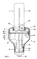
- FIG. 1 shows the side view of a compact low-pressure discharge lamp according to the invention.
- the lamp essentially consists of a discharge vessel 1 and a base 2, the base 2 being composed of a cap 3 and a housing 4.
- the housing 4 has a cylindrical region and a frustoconical region, to the tip end of which a base sleeve 5 in the form of an E27 base is fastened.
- a mounting plate 8 in the form of a circuit board is arranged in the interior of the cylindrical housing part perpendicular to the longitudinal axis of the lamp and bears conductor tracks on the side facing the discharge vessel 1 and circuit elements 9 of a ballast arrangement on the side facing the base sleeve 5.
- the ballast arrangement is electrically connected to the base sleeve 5 via mains connection lines 10, 11, a fuse cartridge 13 being additionally connected in the line 11, which is soldered to the ground contact 12 of the base sleeve 5.
- the discharge vessel consists of two U-shaped tube pieces 14, 15, one leg of each tube piece 14, 15 carrying an electrode 16, 17 and the other two legs through a passage 18 with one another are connected.
- the free ends the pipe sections 14, 15 are sealed gas-tight by bruises 19, 20 and sit inside the base cap 3, where they are fastened by means of putty 21.
- a pump stem 22 is fused to the electrode-free end of the pipe section 14.
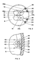
- the base cap 3 has four retaining pins 23 to 26 in the extension of the edge, the ends of the two current leads 27a, b and 28a, b of the electrodes 16, on adjacent retaining pins 23, 24 and 25, 26, as shown in FIG. 17 are performed.
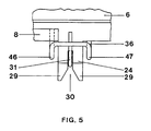
- the holding pins 23 to 26, as can be seen from FIGS. 3 to 5, have a rectangular cross section with a width of 3 mm and a thickness of 1.5 mm and are 6 mm long.
- the free end of the holding pins 23 to 26 has, as shown for the holding pin 24 in FIGS. 4 and 5, a bevel 29 and is provided with a notch 30.
- the ends of the power supply lines 27a, b and 28a, b, as shown for the end 31, are guided along the inner broad side to the free end of the holding pin 24. From there, they are led back through the notch 30 and on the outer broad side to the starting point of the holding pin 24. Between the ends of the power supply lines 27a, b and 28a, b, as shown for the end 31, there must be a sufficiently large creepage distance up to the parting line 3a between the cap 3 and the housing 4 so that no current flow occurs on the base 2. All current leads, as can be seen for the current leads 27b and (partially shown) 27a in FIG.
- vacuvite wire 32a, b in the area of the crimps 19 and tin-plated wire 31 in the area of the holding pin 24.
- Wire 33a, b inserted by butt welding.
- the diameter of the power supply lines (27a, b; 28a, b) is 0.4 mm.
- the mounting plate 8 designed as a board is fixed with the aid of retaining ribs 34 (see FIG. 1) on the inner wall of the cylindrical part of the base housing 4 so that when the base 2 is assembled, the surface provided with the conductor tracks at the level of the respective attachment area of the holding pins 23 to 26 lies.
- the mounting plate 8 extends almost to the inner wall of the base housing 4 and has 23 to 26 recesses in the region of the holding pins.
- the electrical connections of the ballast arrangement are also attached to the power supply lines there. They consist, as can be seen from FIGS.
- the right-angled corners 39, 40 of the bow-shaped connecting wires 35 to 38 lie on ribs 44, 45 with a rectangular cross section and a height of 1 mm, which are parallel are attached to the lamp longitudinal axis on the inner wall of the cylindrical part of the base housing 4.
- the bow-shaped connecting wires 35 to 38 as shown in FIGS. 4 and 5 for the connecting wire 36, are provided with an arcuate bulge 46, 47 near the soldering fastenings.
- the U-shaped wire clips 35 to 38 consist of tin-plated wire with a tin layer of at least 4 ⁇ m and have a diameter of 0.5 mm.
Applications Claiming Priority (2)
| Application Number | Priority Date | Filing Date | Title |
|---|---|---|---|
| DE4012684A DE4012684A1 (de) | 1990-04-20 | 1990-04-20 | Kompakte niederdruckentladungslampe |
| DE4012684 | 1990-04-20 |
Publications (2)
| Publication Number | Publication Date |
|---|---|
| EP0452743A1 true EP0452743A1 (fr) | 1991-10-23 |
| EP0452743B1 EP0452743B1 (fr) | 1994-09-14 |
Family
ID=6404775
Family Applications (1)
| Application Number | Title | Priority Date | Filing Date |
|---|---|---|---|
| EP91105379A Expired - Lifetime EP0452743B1 (fr) | 1990-04-20 | 1991-04-05 | Lampe à décharge compacte à basse pression |
Country Status (7)
| Country | Link |
|---|---|
| US (1) | US5289079A (fr) |
| EP (1) | EP0452743B1 (fr) |
| JP (1) | JP3095805B2 (fr) |
| KR (1) | KR100201664B1 (fr) |
| CA (1) | CA2040835C (fr) |
| DE (2) | DE4012684A1 (fr) |
| HU (1) | HU206788B (fr) |
Cited By (6)
| Publication number | Priority date | Publication date | Assignee | Title |
|---|---|---|---|---|
| EP0622822A1 (fr) * | 1993-04-16 | 1994-11-02 | TUNGSRAM Részvénytársaság | Lampe à décharge à bas pression à culotage d'un seul coté. |
| EP0854497A2 (fr) * | 1997-01-15 | 1998-07-22 | Patent-Treuhand-Gesellschaft für elektrische Glühlampen mbH | Lampe compacte à décharge basse pression |
| EP0854496A2 (fr) * | 1997-01-15 | 1998-07-22 | Patent-Treuhand-Gesellschaft für elektrische Glühlampen mbH | Lampe compacte à décharge basse pression |
| EP0923105A1 (fr) * | 1997-12-11 | 1999-06-16 | Patent-Treuhand-Gesellschaft für elektrische Glühlampen mbH | Lampe à décharge à basse pression de type compact |
| DE19755538A1 (de) * | 1997-12-13 | 1999-06-24 | Bruno Dietze Fa | Leuchtstoffentladungslampe mit Überstromsicherung |
| US6774564B1 (en) | 1999-06-23 | 2004-08-10 | Patent-Treuhand-Gesellshaft Fuer Elektrische Gluehlampen | Method for mounting the base of an electric lamp |
Families Citing this family (23)
| Publication number | Priority date | Publication date | Assignee | Title |
|---|---|---|---|---|
| DE4241314A1 (de) * | 1992-12-08 | 1994-06-09 | Holzer Walter | Kompaktlampe mit Adapter |
| US5428515A (en) * | 1994-01-07 | 1995-06-27 | Jung; Huang H. | Electric lighting assembly |
| HU214132B (en) * | 1994-01-25 | 1997-12-29 | Ge Lighting Tungsram Rt | Discharge lamp having its cap at one side |
| US5686799A (en) * | 1994-03-25 | 1997-11-11 | Pacific Scientific Company | Ballast circuit for compact fluorescent lamp |
| US6037722A (en) * | 1994-09-30 | 2000-03-14 | Pacific Scientific | Dimmable ballast apparatus and method for controlling power delivered to a fluorescent lamp |
| US5691606A (en) * | 1994-09-30 | 1997-11-25 | Pacific Scientific Company | Ballast circuit for fluorescent lamp |
| US5821699A (en) * | 1994-09-30 | 1998-10-13 | Pacific Scientific | Ballast circuit for fluorescent lamps |
| HU213598B (en) * | 1994-10-18 | 1997-08-28 | Ge Lighting Tungsram Rt | One-side socketed discharge lamp |
| DE29500790U1 (de) * | 1995-01-19 | 1995-04-06 | Piruzram Mansur | Energiesparlampe |
| US5772310A (en) * | 1995-07-05 | 1998-06-30 | General Electric Company | Discharge lamp cap and method for fixing the discharge tube |
| US5751105A (en) * | 1995-12-15 | 1998-05-12 | General Electric Company | Assembly arrangement for a compact fluorescent lamp |
| US5925986A (en) * | 1996-05-09 | 1999-07-20 | Pacific Scientific Company | Method and apparatus for controlling power delivered to a fluorescent lamp |
| US5866993A (en) * | 1996-11-14 | 1999-02-02 | Pacific Scientific Company | Three-way dimming ballast circuit with passive power factor correction |
| US5798617A (en) * | 1996-12-18 | 1998-08-25 | Pacific Scientific Company | Magnetic feedback ballast circuit for fluorescent lamp |
| DE29818340U1 (de) * | 1998-10-14 | 1999-03-18 | Muessli Daniel | Energiesparlampe mit elektronischem Vorschaltgerät |
| US6488538B1 (en) * | 1999-11-02 | 2002-12-03 | Matsushita Electric Industrial Co., Ltd. | Tube lamp and its manufacturing method |
| US6346767B1 (en) * | 1999-12-08 | 2002-02-12 | Osram Sylvania Inc. | Lamp with formed, cemented clip to secure base to lamp |
| CN1203522C (zh) * | 2000-03-21 | 2005-05-25 | 皇家菲利浦电子有限公司 | 放电灯 |
| US6332796B1 (en) * | 2000-10-10 | 2001-12-25 | Chuan-Ying Chen | Structure of a fluorescent tube seat |
| US6764328B2 (en) * | 2000-11-17 | 2004-07-20 | Koninklijke Philips Electronics N.V. | Electric lamp and shaped metal body for use therein |
| US20030185020A1 (en) * | 2002-03-28 | 2003-10-02 | All-Line Inc. | LED bulb for night-light |
| US7758223B2 (en) | 2005-04-08 | 2010-07-20 | Toshiba Lighting & Technology Corporation | Lamp having outer shell to radiate heat of light source |
| CN104716015B (zh) * | 2015-03-20 | 2018-10-23 | 四川联恺照明有限公司 | 荧光灯 |
Citations (2)
| Publication number | Priority date | Publication date | Assignee | Title |
|---|---|---|---|---|
| EP0179473A2 (fr) * | 1984-10-25 | 1986-04-30 | Patent-Treuhand-Gesellschaft für elektrische Glühlampen mbH | Adaptateur pour une lampe à décharge à basse pression à culot unique |
| EP0349083A1 (fr) * | 1988-07-01 | 1990-01-03 | Koninklijke Philips Electronics N.V. | Lampe électrique |
Family Cites Families (6)
| Publication number | Priority date | Publication date | Assignee | Title |
|---|---|---|---|---|
| DE179251C (fr) * | ||||
| US3233207A (en) * | 1964-02-21 | 1966-02-01 | Joseph M Ahroni | Decorative light |
| DE3439171A1 (de) * | 1984-10-25 | 1986-05-07 | Patent-Treuhand-Gesellschaft für elektrische Glühlampen mbH, 8000 München | Einseitig gesockelte quecksilberdampfniederdruckentladungslampe |
| US5018992A (en) * | 1988-05-20 | 1991-05-28 | Gte Products Corporation | Wedge lamp and clip |
| JPH0770306B2 (ja) * | 1988-12-01 | 1995-07-31 | 株式会社小糸製作所 | 口金付電球 |
| US4936789A (en) * | 1989-08-01 | 1990-06-26 | Joseph Ugalde | Method and apparatus for preventing the theft of a fluorescent lamp and ballast transformer |
-
1990
- 1990-04-20 DE DE4012684A patent/DE4012684A1/de not_active Withdrawn
-
1991
- 1991-04-05 DE DE59102894T patent/DE59102894D1/de not_active Expired - Fee Related
- 1991-04-05 EP EP91105379A patent/EP0452743B1/fr not_active Expired - Lifetime
- 1991-04-11 JP JP03106858A patent/JP3095805B2/ja not_active Expired - Fee Related
- 1991-04-15 US US07/685,547 patent/US5289079A/en not_active Expired - Lifetime
- 1991-04-19 CA CA002040835A patent/CA2040835C/fr not_active Expired - Lifetime
- 1991-04-19 HU HU911309A patent/HU206788B/hu not_active IP Right Cessation
- 1991-04-20 KR KR1019910006347A patent/KR100201664B1/ko not_active IP Right Cessation
Patent Citations (2)
| Publication number | Priority date | Publication date | Assignee | Title |
|---|---|---|---|---|
| EP0179473A2 (fr) * | 1984-10-25 | 1986-04-30 | Patent-Treuhand-Gesellschaft für elektrische Glühlampen mbH | Adaptateur pour une lampe à décharge à basse pression à culot unique |
| EP0349083A1 (fr) * | 1988-07-01 | 1990-01-03 | Koninklijke Philips Electronics N.V. | Lampe électrique |
Cited By (11)
| Publication number | Priority date | Publication date | Assignee | Title |
|---|---|---|---|---|
| EP0622822A1 (fr) * | 1993-04-16 | 1994-11-02 | TUNGSRAM Részvénytársaság | Lampe à décharge à bas pression à culotage d'un seul coté. |
| EP0854497A2 (fr) * | 1997-01-15 | 1998-07-22 | Patent-Treuhand-Gesellschaft für elektrische Glühlampen mbH | Lampe compacte à décharge basse pression |
| EP0854496A2 (fr) * | 1997-01-15 | 1998-07-22 | Patent-Treuhand-Gesellschaft für elektrische Glühlampen mbH | Lampe compacte à décharge basse pression |
| EP0854496A3 (fr) * | 1997-01-15 | 1998-09-30 | Patent-Treuhand-Gesellschaft für elektrische Glühlampen mbH | Lampe compacte à décharge basse pression |
| EP0854497A3 (fr) * | 1997-01-15 | 1998-10-07 | Patent-Treuhand-Gesellschaft für elektrische Glühlampen mbH | Lampe compacte à décharge basse pression |
| US6008570A (en) * | 1997-01-15 | 1999-12-28 | Patent-Treuhand-Gesellschaft Fuer Elektrische Gluehlampen Mbh | Compact low-pressure discharge lamp with conductive spring element |
| US6011347A (en) * | 1997-01-15 | 2000-01-04 | Patent-Treuhand-Gesellschaft Fuer Elektrische Gluehlampen Gmbh | Compact low-pressure discharge lamp utilizing helical or spiral springs to connect the supply leads of the lamp envelope to the electric terminals within the lamp cap |
| EP0923105A1 (fr) * | 1997-12-11 | 1999-06-16 | Patent-Treuhand-Gesellschaft für elektrische Glühlampen mbH | Lampe à décharge à basse pression de type compact |
| DE19755538A1 (de) * | 1997-12-13 | 1999-06-24 | Bruno Dietze Fa | Leuchtstoffentladungslampe mit Überstromsicherung |
| DE19755538C2 (de) * | 1997-12-13 | 2003-03-06 | Bruno Dietze Fa | Leuchtstoffentladungslampe mit Überstromsicherung |
| US6774564B1 (en) | 1999-06-23 | 2004-08-10 | Patent-Treuhand-Gesellshaft Fuer Elektrische Gluehlampen | Method for mounting the base of an electric lamp |
Also Published As
| Publication number | Publication date |
|---|---|
| KR910019104A (ko) | 1991-11-30 |
| DE59102894D1 (de) | 1994-10-20 |
| CA2040835C (fr) | 2001-10-23 |
| HU206788B (en) | 1992-12-28 |
| HU911309D0 (en) | 1991-10-28 |
| KR100201664B1 (ko) | 1999-06-15 |
| HUT57469A (en) | 1991-11-28 |
| US5289079A (en) | 1994-02-22 |
| DE4012684A1 (de) | 1991-10-24 |
| JP3095805B2 (ja) | 2000-10-10 |
| EP0452743B1 (fr) | 1994-09-14 |
| JPH04230902A (ja) | 1992-08-19 |
| CA2040835A1 (fr) | 1991-10-21 |
Similar Documents
| Publication | Publication Date | Title |
|---|---|---|
| EP0452743B1 (fr) | Lampe à décharge compacte à basse pression | |
| DE19857802A1 (de) | Kompakte Leuchtstofflampe mit internen Verbindungen | |
| DE69726105T2 (de) | Elektrische lampe | |
| EP2002462B1 (fr) | Lampe munie d'une lampe encastrée | |
| EP0854497B1 (fr) | Lampe compacte à décharge basse pression | |
| DD284098A5 (de) | Elektrische lampe | |
| DE3439171A1 (de) | Einseitig gesockelte quecksilberdampfniederdruckentladungslampe | |
| EP0854496B1 (fr) | Lampe compacte à décharge basse pression | |
| DE2605433A1 (de) | Elektrische gluehlampe mit zentrierring | |
| EP0310792B1 (fr) | Lampe de signalisation à monter sur des plaques de circuits | |
| EP0923105B1 (fr) | Lampe à décharge à basse pression de type compact | |
| DE4201779A1 (de) | Niederdruckentladungslampe | |
| DE102007035596A1 (de) | Elektrische Lampe mit einem Außenkolben und einer Einbaulampe sowie ein Verfahren zu deren Herstellung | |
| EP1147534A1 (fr) | Lampe a decharge | |
| EP0878870A1 (fr) | Connecteur coaxial pour hyper-fréquences | |
| DE60124465T2 (de) | Entladungslampe | |
| DE2245365C3 (de) | Geteilter Sockel für eine ringförmige Leuchtstofflampe | |
| EP1329932B1 (fr) | Lampe compacte à décharge à basse pression | |
| DE19757783A1 (de) | Einendige Entladungslampe | |
| EP0179251A2 (fr) | Lampe à décharge à vapeur de mercure à basse pression avec culot unique | |
| EP0914674A1 (fr) | Ampoule electrique | |
| DE2700109A1 (de) | Anschluss- und stuetzeinrichtung fuer einen roehrenheizfaden | |
| CH357101A (de) | Lösbare Steckkontaktverbindungs-Einrichtung, enthaltend eine Kontaktfederanordnung und ein Kontaktmesser, bei der die Kontaktfederanordnung in einer Federleiste Aufnahme findet | |
| EP0906645B1 (fr) | Platine à circuit imprimé avec douille et culot pour petite lampe à incandence | |
| DE102005034673A1 (de) | Elektrische Lampe |
Legal Events
| Date | Code | Title | Description |
|---|---|---|---|
| PUAI | Public reference made under article 153(3) epc to a published international application that has entered the european phase |
Free format text: ORIGINAL CODE: 0009012 |
|
| AK | Designated contracting states |
Kind code of ref document: A1 Designated state(s): DE FR GB IT SE |
|
| 17P | Request for examination filed |
Effective date: 19911127 |
|
| 17Q | First examination report despatched |
Effective date: 19931228 |
|
| GRAA | (expected) grant |
Free format text: ORIGINAL CODE: 0009210 |
|
| AK | Designated contracting states |
Kind code of ref document: B1 Designated state(s): DE FR GB IT SE |
|
| REF | Corresponds to: |
Ref document number: 59102894 Country of ref document: DE Date of ref document: 19941020 |
|
| ITF | It: translation for a ep patent filed |
Owner name: STUDIO JAUMANN |
|
| GBT | Gb: translation of ep patent filed (gb section 77(6)(a)/1977) |
Effective date: 19941123 |
|
| EAL | Se: european patent in force in sweden |
Ref document number: 91105379.1 |
|
| ET | Fr: translation filed | ||
| PLBE | No opposition filed within time limit |
Free format text: ORIGINAL CODE: 0009261 |
|
| STAA | Information on the status of an ep patent application or granted ep patent |
Free format text: STATUS: NO OPPOSITION FILED WITHIN TIME LIMIT |
|
| 26N | No opposition filed | ||
| REG | Reference to a national code |
Ref country code: GB Ref legal event code: IF02 |
|
| PGFP | Annual fee paid to national office [announced via postgrant information from national office to epo] |
Ref country code: DE Payment date: 20080620 Year of fee payment: 18 |
|
| PGFP | Annual fee paid to national office [announced via postgrant information from national office to epo] |
Ref country code: FR Payment date: 20090424 Year of fee payment: 19 Ref country code: IT Payment date: 20090428 Year of fee payment: 19 Ref country code: SE Payment date: 20090407 Year of fee payment: 19 |
|
| PGFP | Annual fee paid to national office [announced via postgrant information from national office to epo] |
Ref country code: GB Payment date: 20090409 Year of fee payment: 19 |
|
| PG25 | Lapsed in a contracting state [announced via postgrant information from national office to epo] |
Ref country code: DE Free format text: LAPSE BECAUSE OF NON-PAYMENT OF DUE FEES Effective date: 20091103 |
|
| EUG | Se: european patent has lapsed | ||
| GBPC | Gb: european patent ceased through non-payment of renewal fee |
Effective date: 20100405 |
|
| REG | Reference to a national code |
Ref country code: FR Ref legal event code: ST Effective date: 20101230 |
|
| PG25 | Lapsed in a contracting state [announced via postgrant information from national office to epo] |
Ref country code: GB Free format text: LAPSE BECAUSE OF NON-PAYMENT OF DUE FEES Effective date: 20100405 Ref country code: IT Free format text: LAPSE BECAUSE OF NON-PAYMENT OF DUE FEES Effective date: 20100405 |
|
| PG25 | Lapsed in a contracting state [announced via postgrant information from national office to epo] |
Ref country code: FR Free format text: LAPSE BECAUSE OF NON-PAYMENT OF DUE FEES Effective date: 20100430 |
|
| PG25 | Lapsed in a contracting state [announced via postgrant information from national office to epo] |
Ref country code: SE Free format text: LAPSE BECAUSE OF NON-PAYMENT OF DUE FEES Effective date: 20100406 |