EP0452743A1 - Compact low pressure discharge lamp - Google Patents
Compact low pressure discharge lamp Download PDFInfo
- Publication number
- EP0452743A1 EP0452743A1 EP91105379A EP91105379A EP0452743A1 EP 0452743 A1 EP0452743 A1 EP 0452743A1 EP 91105379 A EP91105379 A EP 91105379A EP 91105379 A EP91105379 A EP 91105379A EP 0452743 A1 EP0452743 A1 EP 0452743A1
- Authority
- EP
- European Patent Office
- Prior art keywords
- base
- pressure discharge
- discharge lamp
- compact low
- lamp according
- Prior art date
- Legal status (The legal status is an assumption and is not a legal conclusion. Google has not performed a legal analysis and makes no representation as to the accuracy of the status listed.)
- Granted
Links
Images

Classifications
-
- H—ELECTRICITY
- H01—ELECTRIC ELEMENTS
- H01J—ELECTRIC DISCHARGE TUBES OR DISCHARGE LAMPS
- H01J5/00—Details relating to vessels or to leading-in conductors common to two or more basic types of discharge tubes or lamps
- H01J5/50—Means forming part of the tube or lamps for the purpose of providing electrical connection to it
- H01J5/54—Means forming part of the tube or lamps for the purpose of providing electrical connection to it supported by a separate part, e.g. base
-
- H—ELECTRICITY
- H01—ELECTRIC ELEMENTS
- H01J—ELECTRIC DISCHARGE TUBES OR DISCHARGE LAMPS
- H01J61/00—Gas-discharge or vapour-discharge lamps
- H01J61/02—Details
- H01J61/30—Vessels; Containers
-
- Y—GENERAL TAGGING OF NEW TECHNOLOGICAL DEVELOPMENTS; GENERAL TAGGING OF CROSS-SECTIONAL TECHNOLOGIES SPANNING OVER SEVERAL SECTIONS OF THE IPC; TECHNICAL SUBJECTS COVERED BY FORMER USPC CROSS-REFERENCE ART COLLECTIONS [XRACs] AND DIGESTS
- Y02—TECHNOLOGIES OR APPLICATIONS FOR MITIGATION OR ADAPTATION AGAINST CLIMATE CHANGE
- Y02B—CLIMATE CHANGE MITIGATION TECHNOLOGIES RELATED TO BUILDINGS, e.g. HOUSING, HOUSE APPLIANCES OR RELATED END-USER APPLICATIONS
- Y02B20/00—Energy efficient lighting technologies, e.g. halogen lamps or gas discharge lamps
Definitions
- the invention relates to a compact low-pressure discharge lamp, consisting of a discharge vessel with electrodes and power supply lines and a base composed of a cap, housing and mounting plate with ballast arrangement according to the preamble of claim 1.
- Compact low-pressure discharge lamps of this type where the discharge vessel usually consists of a single or multiple bent tube and a circuit board with a soldered electronic ballast assembly is integrated in the base as a mounting plate, are increasingly replacing the incandescent lamp in the home and living area.
- the manufacturing costs for these compact low-pressure discharge lamps have so far been quite high, since many complicated manufacturing steps are necessary in the manufacture.
- One of these manufacturing steps is the electrical connection of the power supply lines of the discharge vessel to the corresponding connections of the ballast arrangement. To make this connection, the corresponding connecting wires have so far mostly been brought together and crimped with a metal sleeve.
- EP-A-179 251 there is one low-pressure discharge lamp with a base on one side, in which the electrical connection of electrodes and ballast takes place by means of contact pins in the cap, which engage in counter-contacts on the mounting plate during assembly.
- the current leads of the electrodes are clamped in corresponding receptacles on the contact pins.
- a contacting system is very complex since additional contacting elements have to be installed in the cap and mounting plate. In addition, these contacting elements increase the manufacturing costs.
- the object of the invention is to enable a simple mechanical connection of the power supply lines of the discharge vessel to the corresponding connections of the ballast arrangement by means of a special structure of the lamp in the region of the base and the mounting plate.
- the structure required for this contact should be as simple and inexpensive to manufacture as possible.
- the ends of the power supply lines are aligned perpendicular to the bow-shaped connecting wires of the ballast arrangement, which run essentially parallel to the mounting plate.
- the respective wires to be contacted are arranged approximately at right angles one behind the other and with With the help of the retaining pin and the inner wall of the base housing resiliently pressed against each other, so that an electrical connection between electrodes and ballast is made.
- the alignment of the power supply lines is particularly simple if the holding pins are formed from the extended edge of the base cap and have a notch for fixing the power supply lines at the free end. The ends of the power leads are then - coming from the interior of the cap - through the notch and a piece along the outer wall of the rectangular retaining pin.
- the connecting wires of the ballast arrangement advantageously consist of U-shaped wire clips, the two ends of which are soldered to the corresponding conductor track on the edge of the mounting plate.
- the U-shaped wire brackets have right-angled corners and are arranged on the side of the mounting plate facing the base sleeve. They protrude only slightly beyond the edge of the mounting plate and lie with their right-angled corners on the ends of ribs with a rectangular cross section, which are attached to the inner wall of the cylindrical region of the housing parallel to the lamp longitudinal axis. Due to the arcuate bulges of the wire bracket - seen perpendicular to the mounting plate - at the transition to the soldering attachment, a spring effect is additionally achieved in the radial direction on the inner wall of the housing.
- the retaining pins When assembling the housing and mounting plate with the cap, the retaining pins are through the U-shaped wire bracket inserted, so that the ends of the power leads abutting the outer wall of the retaining pin intersect with the U-shaped wire bracket of the ballast connections. To facilitate this manufacturing step, the ends of the retaining pins are chamfered. To ensure that there is sufficient free space within the U-shaped wire bracket for the holding pins and the power supply lines, additional notches are made on the mounting plate between the two solder fastenings of each wire bracket. The ribs on the inner wall of the housing prevent the U-shaped wire brackets from being pushed away and bent by the retaining pins in the direction of the base sleeve when the base is being assembled.
- One or more contact ribs with a triangular cross section and a lower height are additionally attached between the two ribs for supporting the wire bracket corners.
- the purpose of these abutment ribs is to press the part of the wire bracket between the right-angled corners against the retaining pin and thus against the ends of the respective power supply when the base is connected.
- the ends of the power leads in the area of the holding pins and the bow-shaped connecting wires consist of tinned wires with at least 4 ⁇ m tin coating.
- the tinning guarantees safe and permanent contacting without oxidation.
- the power supplies consist of a wire composed of 50% iron, 47% nickel and 3% chromium (brand name Vacuvit), a material particularly suitable for gas-tight melts. Since Vacuvit wire oxidizes, A direct connection of Vacuvit wire with tinned wire can lead to lamp failure in the long term.
- a piece of copper sheathed wire (trademark KPS wire, a steel wire with a copper sheath) is inserted between the end of the Vacuvit wire and the tinned wire.
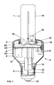
- FIG. 1 shows the side view of a compact low-pressure discharge lamp according to the invention.
- the lamp essentially consists of a discharge vessel 1 and a base 2, the base 2 being composed of a cap 3 and a housing 4.
- the housing 4 has a cylindrical region and a frustoconical region, to the tip end of which a base sleeve 5 in the form of an E27 base is fastened.
- a mounting plate 8 in the form of a circuit board is arranged in the interior of the cylindrical housing part perpendicular to the longitudinal axis of the lamp and bears conductor tracks on the side facing the discharge vessel 1 and circuit elements 9 of a ballast arrangement on the side facing the base sleeve 5.
- the ballast arrangement is electrically connected to the base sleeve 5 via mains connection lines 10, 11, a fuse cartridge 13 being additionally connected in the line 11, which is soldered to the ground contact 12 of the base sleeve 5.
- the discharge vessel consists of two U-shaped tube pieces 14, 15, one leg of each tube piece 14, 15 carrying an electrode 16, 17 and the other two legs through a passage 18 with one another are connected.
- the free ends the pipe sections 14, 15 are sealed gas-tight by bruises 19, 20 and sit inside the base cap 3, where they are fastened by means of putty 21.
- a pump stem 22 is fused to the electrode-free end of the pipe section 14.
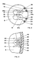
- the base cap 3 has four retaining pins 23 to 26 in the extension of the edge, the ends of the two current leads 27a, b and 28a, b of the electrodes 16, on adjacent retaining pins 23, 24 and 25, 26, as shown in FIG. 17 are performed.
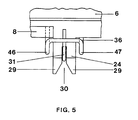
- the holding pins 23 to 26, as can be seen from FIGS. 3 to 5, have a rectangular cross section with a width of 3 mm and a thickness of 1.5 mm and are 6 mm long.
- the free end of the holding pins 23 to 26 has, as shown for the holding pin 24 in FIGS. 4 and 5, a bevel 29 and is provided with a notch 30.
- the ends of the power supply lines 27a, b and 28a, b, as shown for the end 31, are guided along the inner broad side to the free end of the holding pin 24. From there, they are led back through the notch 30 and on the outer broad side to the starting point of the holding pin 24. Between the ends of the power supply lines 27a, b and 28a, b, as shown for the end 31, there must be a sufficiently large creepage distance up to the parting line 3a between the cap 3 and the housing 4 so that no current flow occurs on the base 2. All current leads, as can be seen for the current leads 27b and (partially shown) 27a in FIG.
- vacuvite wire 32a, b in the area of the crimps 19 and tin-plated wire 31 in the area of the holding pin 24.
- Wire 33a, b inserted by butt welding.
- the diameter of the power supply lines (27a, b; 28a, b) is 0.4 mm.
- the mounting plate 8 designed as a board is fixed with the aid of retaining ribs 34 (see FIG. 1) on the inner wall of the cylindrical part of the base housing 4 so that when the base 2 is assembled, the surface provided with the conductor tracks at the level of the respective attachment area of the holding pins 23 to 26 lies.
- the mounting plate 8 extends almost to the inner wall of the base housing 4 and has 23 to 26 recesses in the region of the holding pins.
- the electrical connections of the ballast arrangement are also attached to the power supply lines there. They consist, as can be seen from FIGS.
- the right-angled corners 39, 40 of the bow-shaped connecting wires 35 to 38 lie on ribs 44, 45 with a rectangular cross section and a height of 1 mm, which are parallel are attached to the lamp longitudinal axis on the inner wall of the cylindrical part of the base housing 4.
- the bow-shaped connecting wires 35 to 38 as shown in FIGS. 4 and 5 for the connecting wire 36, are provided with an arcuate bulge 46, 47 near the soldering fastenings.
- the U-shaped wire clips 35 to 38 consist of tin-plated wire with a tin layer of at least 4 ⁇ m and have a diameter of 0.5 mm.
Abstract
Description
Die Erfindung betrifft eine kompakte Niederdruckentladungslampe, bestehend aus einem Entladungsgefäß mit Elektroden und Stromzuführungen und einem aus Kappe, Gehäuse und Montageplatte mit Vorschaltanordnung zusammengesetzten Sockel gemäß dem Oberbegriff des Anspruchs 1.The invention relates to a compact low-pressure discharge lamp, consisting of a discharge vessel with electrodes and power supply lines and a base composed of a cap, housing and mounting plate with ballast arrangement according to the preamble of claim 1.
Kompakte Niederdruckentladungslampen dieser Art, wobei das Entladungsgefäß meist aus einem ein- oder mehrfach gebogenen Rohr besteht und im Sockel als Montageplatte eine Schaltungsplatine mit einer darauf verlöteten elektronischen Vorschaltanordnung integriert ist, ersetzen in zunehmendem Maß die Glühlampe im Haus- und Wohnbereich. Die Herstellungskosten für diese kompakten Niederdruckentladungslampen sind bisher noch recht hoch, da viele komplizierte Fertigungsschritte bei der Herstellung notwendig sind. Einer dieser Fertigungsschritte ist die elektrische Verbindung der Stromzuführungen des Entladungsgefäßes mit den entsprechenden Anschlüssen der Vorschaltanordnung. Zur Herstellung dieser Verbindung werden bisher meist die entsprechenden Verbingungsdrähte zusammengeführt und mit einer Metallhülse vercrimpt. In der EP-A-179 251 ist eine einseitig gesockelte Niederdruckentladungslampe beschrieben, bei der die elektrische Verbindung von Elektroden und Vorschaltgerät durch Kontaktstifte in der Kappe erfolgt, die beim Zusammenbau in Gegenkontakte auf der Montageplatte eingreifen. Die Stromzuführungen der Elektroden sind in entsprechende Aufnahmen an den Kontaktstiften eingeklemmt. Ein solches Kontaktierungssystem ist jedoch sehr aufwendig, da zusätzliche Kontaktierungselemente in Kappe und Montageplatte eingebaut werden müssen. Zudem erhöhen diese Kontaktierungselemente die Herstellungskosten.Compact low-pressure discharge lamps of this type, where the discharge vessel usually consists of a single or multiple bent tube and a circuit board with a soldered electronic ballast assembly is integrated in the base as a mounting plate, are increasingly replacing the incandescent lamp in the home and living area. The manufacturing costs for these compact low-pressure discharge lamps have so far been quite high, since many complicated manufacturing steps are necessary in the manufacture. One of these manufacturing steps is the electrical connection of the power supply lines of the discharge vessel to the corresponding connections of the ballast arrangement. To make this connection, the corresponding connecting wires have so far mostly been brought together and crimped with a metal sleeve. In EP-A-179 251 there is one low-pressure discharge lamp with a base on one side, in which the electrical connection of electrodes and ballast takes place by means of contact pins in the cap, which engage in counter-contacts on the mounting plate during assembly. The current leads of the electrodes are clamped in corresponding receptacles on the contact pins. However, such a contacting system is very complex since additional contacting elements have to be installed in the cap and mounting plate. In addition, these contacting elements increase the manufacturing costs.
Aufgabe der Erfindung ist es, durch einen speziellen Aufbau der Lampe im Bereich des Sockels und der Montageplatte eine einfache maschinelle Verbindung der Stromzuführungen des Entladungsgefäßes mit den entsprechenden Anschlüssen der Vorschaltanordnung zu ermöglichen. Der für diese Kontaktierung benötigte Aufbau sollte möglichst einfach und kostengünstig herzustellen sein.The object of the invention is to enable a simple mechanical connection of the power supply lines of the discharge vessel to the corresponding connections of the ballast arrangement by means of a special structure of the lamp in the region of the base and the mounting plate. The structure required for this contact should be as simple and inexpensive to manufacture as possible.
Die Aufgabe wird bei der kompakten Niederdruckentladungslampe durch die kennzeichnenden Merkmale des ersten Anspruchs gelöst. Weitere vorteilhafte Merkmale sind den Unteransprüchen zu entnehmen.The object is achieved in the compact low-pressure discharge lamp by the characterizing features of the first claim. Further advantageous features can be found in the subclaims.
Mit Hilfe der Haltezapfen werden die Enden der Stromzuführungen senkrecht zu den bügelförmigen Anschlußdrähten der Vorschaltanordnung, die im wesentlichen parallel zur Montageplatte verlaufen, ausgerichtet. Beim Zusammenbau von Sockelgehäuse und Montageplatte mit der Sockelkappe werden die jeweiligen zu kontaktierenden Drähte etwa im rechten Winkel hintereinander angeordnet und mit Hilfe des Haltezapfens und der Innenwand des Sockelgehäuses federnd gegeneinandergedrückt, so daß eine elektrische Verbindung zwischen Elektroden und Vorschaltanordnung hergestellt ist.With the help of the holding pins, the ends of the power supply lines are aligned perpendicular to the bow-shaped connecting wires of the ballast arrangement, which run essentially parallel to the mounting plate. When assembling the base housing and mounting plate with the base cap, the respective wires to be contacted are arranged approximately at right angles one behind the other and with With the help of the retaining pin and the inner wall of the base housing resiliently pressed against each other, so that an electrical connection between electrodes and ballast is made.
Besonders einfach gestaltet sich die Ausrichtung der Stromzuführungen, wenn die Haltezapfen aus dem verlängerten Rand der Sockelkappe gebildet sind und zum Fixieren der Stromzuführungen am freien Ende eine Kerbe aufweisen. Die Enden der Stromzuführungen sind dann - aus dem Innenraum der Kappe kommend - durch die Einkerbung und ein Stück an der Außenwand des rechteckigen Haltezapfens entlanggelegt.The alignment of the power supply lines is particularly simple if the holding pins are formed from the extended edge of the base cap and have a notch for fixing the power supply lines at the free end. The ends of the power leads are then - coming from the interior of the cap - through the notch and a piece along the outer wall of the rectangular retaining pin.
Die Anschlußdrähte der Vorschaltanordnung bestehen vorteilhaft aus U-förmig gebogenen Drahtbügeln, dessen beide Enden mit der entsprechenden Leiterbahn am Rande der Montageplatte verlötet sind. Die U-förmigen Drahtbügel besitzen rechtwinklige Ecken und sind auf der der Sockelhülse zugewandten Seite der Montageplatte angeordnet. Sie stehen nur wenig über den Rand der Montageplatte hinaus und liegen mit ihren rechtwinkligen Ecken auf den Enden von Rippen mit rechteckigem Querschnitt auf, die an der Innenwand des zylinderförmigen Bereichs des Gehäuses parallel zur Lampenlängsachse angebracht sind. Durch bogenförmige Ausbuchtungen der Drahtbügel - senkrecht zur Montageplatte gesehen - am Übergang zur Lötbefestigung wird zusätzlich eine Federwirkung in radialer Richtung auf die Innenwand des Gehäuses erreicht.The connecting wires of the ballast arrangement advantageously consist of U-shaped wire clips, the two ends of which are soldered to the corresponding conductor track on the edge of the mounting plate. The U-shaped wire brackets have right-angled corners and are arranged on the side of the mounting plate facing the base sleeve. They protrude only slightly beyond the edge of the mounting plate and lie with their right-angled corners on the ends of ribs with a rectangular cross section, which are attached to the inner wall of the cylindrical region of the housing parallel to the lamp longitudinal axis. Due to the arcuate bulges of the wire bracket - seen perpendicular to the mounting plate - at the transition to the soldering attachment, a spring effect is additionally achieved in the radial direction on the inner wall of the housing.
Beim Zusammenbau von Gehäuse und Montageplatte mit der Kappe werden die Haltezapfen durch die U-förmigen Drahtbügel gesteckt, so daß sich die an der Außenwand des Haltezapfens anliegenden Enden der Stromzuführungen mit den U-förmigen Drahtbügeln der Vorschaltanordnungsanschlüsse kreuzen. Zur Erleichterung dieses Fertigungsschritts sind die Enden der Haltezapfen mit einer Abschrägung versehen. Damit ein genügend großer Freiraum innerhalb der U-förmigen Drahtbügel für die Haltezapfen und die Stromzuführungen vorhanden ist, sind zusätzlich Einkerbungen an der Montageplatte zwischen den beiden Lötbefestigungen jedes Drahtbügels vorgenommen. Die Rippen an der Gehäuseinnenwand verhindern, daß beim Zusammenbau des Sockels die U-förmigen Drahtbügel durch die Haltezapfen in Richtung Sockelhülse weggedrückt und verbogen werden können. Zwischen den beiden Rippen zur Auflage der Drahtbügelecken sind zusätzlich ein oder mehrere Anlagerippen mit dreieckigem Querschnitt und geringerer Höhe angebracht. Diese Anlagerippen haben die Aufgabe, bei verbundenem Sockel den Teil des Drahtbügels zwischen den rechtwinkligen Ecken verstärkt gegen den Haltezapfen und damit gegen die Enden der jeweiligen Stromzuführung zu drücken.When assembling the housing and mounting plate with the cap, the retaining pins are through the U-shaped wire bracket inserted, so that the ends of the power leads abutting the outer wall of the retaining pin intersect with the U-shaped wire bracket of the ballast connections. To facilitate this manufacturing step, the ends of the retaining pins are chamfered. To ensure that there is sufficient free space within the U-shaped wire bracket for the holding pins and the power supply lines, additional notches are made on the mounting plate between the two solder fastenings of each wire bracket. The ribs on the inner wall of the housing prevent the U-shaped wire brackets from being pushed away and bent by the retaining pins in the direction of the base sleeve when the base is being assembled. One or more contact ribs with a triangular cross section and a lower height are additionally attached between the two ribs for supporting the wire bracket corners. The purpose of these abutment ribs is to press the part of the wire bracket between the right-angled corners against the retaining pin and thus against the ends of the respective power supply when the base is connected.
Die Enden der Stromzuführungen im Bereich der Haltezapfen und die bügelförmigen Anschlußdrähte bestehen aus verzinnten Drähten mit mindestens 4 µm Zinnauflage. Die Verzinnung garantiert eine sichere und dauerhafte Kontaktierung ohne Oxidation. Im Bereich der Quetschungen bestehen die Stromzuführungen aus einem aus 50 % Eisen, 47 % Nickel und 3 % Chrom (Markenname Vacuvit) zusammengesetzten Draht, ein besonders für gasdichte Einschmelzungen geeignetes Material. Da Vacuvit-Draht oxidiert, kann eine direkte Verbindung von Vacuvit-Draht mit verzinntem Draht längerfristig zu einem Ausfall der Lampe führen. Zur Erleichterung der Stumpfschweißung ist zwischen das Ende des Vacuvit-Drahtes und den verzinnten Draht ein Stück Kupfermanteldraht (Warenzeichen KPS-Draht, ein Stahldraht mit einem Kupfermantel) eingefügt.The ends of the power leads in the area of the holding pins and the bow-shaped connecting wires consist of tinned wires with at least 4 µm tin coating. The tinning guarantees safe and permanent contacting without oxidation. In the area of the bruises, the power supplies consist of a wire composed of 50% iron, 47% nickel and 3% chromium (brand name Vacuvit), a material particularly suitable for gas-tight melts. Since Vacuvit wire oxidizes, A direct connection of Vacuvit wire with tinned wire can lead to lamp failure in the long term. To facilitate butt welding, a piece of copper sheathed wire (trademark KPS wire, a steel wire with a copper sheath) is inserted between the end of the Vacuvit wire and the tinned wire.
Die Erfindung ist anhand eines Ausführungsbeispiels in den nachfolgenden Figuren näher veranschaulicht.
- Figur 1
- zeigt eine Seitenansicht einer teilweise geschnittenen kompakten Niederdruckentladungslampe
Figur 2- zeigt in Draufsicht schematisiert den Verlauf der Stromzuführungen vom Entladungsgefäß zur Steckkontaktierung mit den bügelförmigen Anschlußdrähten der Vorschaltanordnung
Figur 3- zeigt in Draufsicht die Steckkontaktierung der Stromzuführungen mit den bügelförmigen Anschlußdrähten
Figur 4- zeigt in Seitenansicht den Verlauf der Stromzuführungen vom Entladungsgefäß zur Steckkontaktierung mit den bügelförmigen Anschlußdrähten
Figur 5- zeigt eine Frontansicht der Haltezapfen mit den Enden der Stromzuführungen und den bügelförmigen Anschlußdrähten
- Figure 1
- shows a side view of a partially cut compact low-pressure discharge lamp
- Figure 2
- shows a schematic top view of the course of the power supply lines from the discharge vessel to the plug-in contact with the bow-shaped connecting wires of the ballast arrangement
- Figure 3
- shows the top view of the plug contact of the power supplies with the bow-shaped connecting wires
- Figure 4
- shows in side view the course of the power supply lines from the discharge vessel to the plug contact with the bow-shaped connecting wires
- Figure 5
- shows a front view of the holding pin with the ends of the power supply lines and the bow-shaped connecting wires
In Figur 1 ist die Seitenansicht einer erfindungsgemäßen kompakten Niederdruckentladungslampe wiedergegeben. Die Lampe besteht im wesentlichen aus einem Entladungsgefäß 1 und einem Sockel 2, wobei der Sockel 2 aus einer Kappe 3 und einem Gehäuse 4 zusammengesetzt ist. Das Gehäuse 4 weist einen zylinderförmigen Bereich und einen kegelstumpfförmigen Bereich auf, an dessen spitzem Ende eine Sockelhülse 5 in Form eines E27-Sockels befestigt ist. Durch Aufschnappen des inneren Randes des Gehäuses 4 auf den äußeren Rand der Kappe 3, wobei, wie in Fig. 4 vergrößert dargestellt, ein umlaufender Wulst 6 an der Kappe 3 in eine Ringnut 7 am Gehäuse 4 einrastet, wird eine fast unlösbare Verbindung zwischen den beiden Teilen hergestellt.FIG. 1 shows the side view of a compact low-pressure discharge lamp according to the invention. The lamp essentially consists of a discharge vessel 1 and a
Im Innern des zylindrischen Gehäuseteils ist senkrecht zur Lampenlängsachse eine Montageplatte 8 in Form einer Platine angeordnet, die auf der dem Entladungsgefäß 1 zugewandten Seite Leiterbahnen und auf der der Sockelhülse 5 zugewandten Seite Schaltungselemente 9 einer Vorschaltanordnung trägt. Die Vorschaltanordnung ist über Netzanschlußleitungen 10, 11 mit der Sockelhülse 5 elektrisch verbunden, wobei in die Leitung 11, die mit dem Bodenkontakt 12 der Sockelhülse 5 verlötet ist, zusätzlich eine Sicherungspatrone 13 geschaltet ist.A
Das Entladungsgefäß 1 besteht, wie aus den Figuren 1 und 2 ersichtlich, aus zwei U-förmig gebogenen Rohrstücken 14, 15, wobei jeweils ein Schenkel jedes Rohrstücks 14, 15 eine Elektrode 16, 17 trägt und die beiden anderen Schenkel durch einen Durchlaß 18 miteinander verbunden sind. Die freien Enden der Rohrstücke 14, 15 sind durch Quetschungen 19, 20 gasdicht verschlossen und sitzen innerhalb der Sockelkappe 3, wo sie mittels Kitt 21 befestigt sind. Außerdem ist an dem elektrodenfreien Ende des Rohrstücks 14 ein Pumpstengel 22 angeschmolzen.The discharge vessel 1, as can be seen from FIGS. 1 and 2, consists of two
Die Sockelkappe 3 weist in der Verlängerung des Randes vier Haltezapfen 23 bis 26 auf, wobei an benachbarte Haltezapfen 23, 24 und 25, 26, wie in Figur 2 dargestellt, die Enden der beiden Stromzuführungen 27a, b und 28a, b der Elektroden 16, 17 geführt sind. Die Haltezapfen 23 bis 26 haben, wie aus den Figuren 3 bis 5 ersichtlich, einen rechteckigen Querschnitt mit einer Breite von 3 mm und einer Dicke von 1,5 mm und sind 6 mm lang. Das freie Ende der Haltezapfen 23 bis 26 besitzt, wie für den Haltezapfen 24 in den Figuren 4 und 5 gezeigt, eine Abschrägung 29 und ist mit einer Einkerbung 30 versehen. Die Enden der Stromzuführungen 27a, b und 28a, b sind, wie für das Ende 31 gezeigt, an der inneren Breitseite entlang zum freien Ende des Haltezapfens 24 geführt. Von dort sind sie durch die Einkerbung 30 und an der äußeren Breitseite wieder knapp bis zum Ansatzpunkt des Haltezapfens 24 zurückgeführt. Zwischen den Enden der Stromzuführungen 27a, b und 28a, b muß, wie für das Ende 31 gezeigt, eine genügend große Kriechstrecke bis zur Trennfuge 3a zwischen Kappe 3 und Gehäuse 4 vorhanden sein, damit kein Stromfluß außen am Sockel 2 auftritt. Alle Stromzuführungen bestehen, wie für die Stromzuführungen 27b und (teilweise gezeigt) 27a in Figur 4 zu sehen, im Bereich der Quetschungen 19 aus Vacuvit-Draht 32a, b und im Bereich des Haltezapfens 24 aus verzinntem Draht 31. Dazwischen ist ein Stück KPS-Draht 33a, b durch Stumpfschweißung eingefügt. Der Durchmesser der Stromzuführungen (27a, b; 28a, b) beträgt 0,4 mm.The
Die als Platine ausgeführte Montageplatte 8 ist mit Hilfe von Halterippen 34 (s. Figur 1) an der Innenwand des zylindrischen Teils des Sockelgehäuses 4 so fixiert, daß bei zusammengebautem Sockel 2 die mit den Leiterbahnen versehene Oberfläche in Höhe des jeweiligen Ansatzbereiches der Haltezapfen 23 bis 26 liegt. Die Montageplatte 8 reicht bis fast an die Innenwand des Sockelgehäuses 4 heran und weist im Bereich der Haltezapfen 23 bis 26 Aussparungen auf. Dort sind auch die elektrischen Anschlüsse der Vorschaltanordnung an die Stromzuführungen ange- bracht. Sie bestehen, wie aus den Figuren 2 bis 5 ersichtlich, aus U-förmig gebogenen Drahtbügeln 35 bis 38 mit rechtwinkligen Ecken 39, 40, die mit ihren beiden Enden 41, 42 auf der der Sockelhülse 5 zugewandten Seite in die Montageplatte 8 gesteckt und auf der der Kappe 3 zugewandten Seite der Montageplatte 8 eingelötet sind. Beide Lötstellen sind über eine Leiterbahn auf der Montageplatte 8 mit den Schaltelementen 9 der Vorschaltanordnung verbunden. Damit bei zusammengebautem Sockel 2 die an den Haltezapfen 23 bis 26 befestigten Enden 31 der Stromzuführungen 27a, b und 28a, b keinen ungewollten elektrischen Kontakt mit den Leiterbahnen erhalten, sind zwischen den beiden aufgelöteten Enden 41, 42 jedes U-förmig gebogenen Drahtbügels 35 bis 38 zusätzlich Einkerbungen 43 an der Montageplatte 8 vorgenommen. Die rechtwinkligen Ecken 39, 40 der bügelförmigen Anschlußdrähte 35 bis 38 liegen auf Rippen 44, 45 mit rechteckigem Querschnitt und einer Höhe von 1 mm auf, die parallel zur Lampenlängsachse an der Innenwand des zylindrischen Teils des Sockelgehäuses 4 angebracht sind. Um eine verstärkte Federung zu erhalten, sind die bügelförmigen Anschlußdrähte 35 bis 38, wie in Figur 4 und 5 für den Anschlußdraht 36 gezeigt, nahe den Lötbefestigungen mit einer bogenförmigen Ausbuchtung 46, 47 versehen. Zur guten Kontaktierung und Federkraftverstärkung der U-förmigen Drahtbügel 35 bis 38 mit den Enden 31 der Stromzuführungen 27a, b und 28a, b sind zwischen den Auflagerippen 44, 45 jeweils noch zwei Anlagerippen 48, 49 mit dreieckigem Querschnitt und einer Höhe von 0,2 mm an der Innenwand des Gehäuses 4 angebracht.The mounting
Die U-förmigen Drahtbügel 35 bis 38 bestehen wie die Enden der Stromzuführungen aus verzinntem Draht mit einer Zinnauflage von mindestens 4 µm und haben einen Durchmesser von 0,5 mm.Like the ends of the power supply lines, the U-shaped wire clips 35 to 38 consist of tin-plated wire with a tin layer of at least 4 μm and have a diameter of 0.5 mm.
Claims (20)
Applications Claiming Priority (2)
| Application Number | Priority Date | Filing Date | Title |
|---|---|---|---|
| DE4012684A DE4012684A1 (en) | 1990-04-20 | 1990-04-20 | Compact low-pressure discharge lamp with switching arrangement |
| DE4012684 | 1990-04-20 |
Publications (2)
| Publication Number | Publication Date |
|---|---|
| EP0452743A1 true EP0452743A1 (en) | 1991-10-23 |
| EP0452743B1 EP0452743B1 (en) | 1994-09-14 |
Family
ID=6404775
Family Applications (1)
| Application Number | Title | Priority Date | Filing Date |
|---|---|---|---|
| EP91105379A Expired - Lifetime EP0452743B1 (en) | 1990-04-20 | 1991-04-05 | Compact low pressure discharge lamp |
Country Status (7)
| Country | Link |
|---|---|
| US (1) | US5289079A (en) |
| EP (1) | EP0452743B1 (en) |
| JP (1) | JP3095805B2 (en) |
| KR (1) | KR100201664B1 (en) |
| CA (1) | CA2040835C (en) |
| DE (2) | DE4012684A1 (en) |
| HU (1) | HU206788B (en) |
Cited By (6)
| Publication number | Priority date | Publication date | Assignee | Title |
|---|---|---|---|---|
| EP0622822A1 (en) * | 1993-04-16 | 1994-11-02 | TUNGSRAM Részvénytársaság | Single-ended low-pressure discharge lamp |
| EP0854496A2 (en) * | 1997-01-15 | 1998-07-22 | Patent-Treuhand-Gesellschaft für elektrische Glühlampen mbH | Compact low pressure discharge lamp |
| EP0854497A2 (en) * | 1997-01-15 | 1998-07-22 | Patent-Treuhand-Gesellschaft für elektrische Glühlampen mbH | Compact low pressure discharge lamp |
| EP0923105A1 (en) * | 1997-12-11 | 1999-06-16 | Patent-Treuhand-Gesellschaft für elektrische Glühlampen mbH | Compact low pressure discharge lamp |
| DE19755538A1 (en) * | 1997-12-13 | 1999-06-24 | Bruno Dietze Fa | Fluorescent light with over-current protection |
| US6774564B1 (en) | 1999-06-23 | 2004-08-10 | Patent-Treuhand-Gesellshaft Fuer Elektrische Gluehlampen | Method for mounting the base of an electric lamp |
Families Citing this family (23)
| Publication number | Priority date | Publication date | Assignee | Title |
|---|---|---|---|---|
| DE4241314A1 (en) * | 1992-12-08 | 1994-06-09 | Holzer Walter | Compact gas discharge lamp with socket adaptor - has built-in starter circuit and contacts engaged by electrode contacts of gas discharge envelope |
| US5428515A (en) * | 1994-01-07 | 1995-06-27 | Jung; Huang H. | Electric lighting assembly |
| HU214132B (en) * | 1994-01-25 | 1997-12-29 | Ge Lighting Tungsram Rt | Discharge lamp having its cap at one side |
| US5686799A (en) * | 1994-03-25 | 1997-11-11 | Pacific Scientific Company | Ballast circuit for compact fluorescent lamp |
| US5821699A (en) * | 1994-09-30 | 1998-10-13 | Pacific Scientific | Ballast circuit for fluorescent lamps |
| US6037722A (en) * | 1994-09-30 | 2000-03-14 | Pacific Scientific | Dimmable ballast apparatus and method for controlling power delivered to a fluorescent lamp |
| US5691606A (en) * | 1994-09-30 | 1997-11-25 | Pacific Scientific Company | Ballast circuit for fluorescent lamp |
| HU213598B (en) * | 1994-10-18 | 1997-08-28 | Ge Lighting Tungsram Rt | One-side socketed discharge lamp |
| DE29500790U1 (en) * | 1995-01-19 | 1995-04-06 | Piruzram Mansur | Energy saving lamp |
| US5772310A (en) * | 1995-07-05 | 1998-06-30 | General Electric Company | Discharge lamp cap and method for fixing the discharge tube |
| US5751105A (en) * | 1995-12-15 | 1998-05-12 | General Electric Company | Assembly arrangement for a compact fluorescent lamp |
| US5925986A (en) * | 1996-05-09 | 1999-07-20 | Pacific Scientific Company | Method and apparatus for controlling power delivered to a fluorescent lamp |
| US5866993A (en) * | 1996-11-14 | 1999-02-02 | Pacific Scientific Company | Three-way dimming ballast circuit with passive power factor correction |
| US5798617A (en) * | 1996-12-18 | 1998-08-25 | Pacific Scientific Company | Magnetic feedback ballast circuit for fluorescent lamp |
| DE29818340U1 (en) * | 1998-10-14 | 1999-03-18 | Muessli Daniel | Energy saving lamp with electronic ballast |
| US6488538B1 (en) * | 1999-11-02 | 2002-12-03 | Matsushita Electric Industrial Co., Ltd. | Tube lamp and its manufacturing method |
| US6346767B1 (en) * | 1999-12-08 | 2002-02-12 | Osram Sylvania Inc. | Lamp with formed, cemented clip to secure base to lamp |
| JP4580609B2 (en) * | 2000-03-21 | 2010-11-17 | コーニンクレッカ フィリップス エレクトロニクス エヌ ヴィ | Discharge lamp |
| US6332796B1 (en) * | 2000-10-10 | 2001-12-25 | Chuan-Ying Chen | Structure of a fluorescent tube seat |
| CN1227701C (en) * | 2000-11-17 | 2005-11-16 | 皇家菲利浦电子有限公司 | Electric lamp and shaped metal body for use therein |
| US20030185020A1 (en) * | 2002-03-28 | 2003-10-02 | All-Line Inc. | LED bulb for night-light |
| US7758223B2 (en) * | 2005-04-08 | 2010-07-20 | Toshiba Lighting & Technology Corporation | Lamp having outer shell to radiate heat of light source |
| CN104716015B (en) * | 2015-03-20 | 2018-10-23 | 四川联恺照明有限公司 | Fluorescent lamp |
Citations (2)
| Publication number | Priority date | Publication date | Assignee | Title |
|---|---|---|---|---|
| EP0179473A2 (en) * | 1984-10-25 | 1986-04-30 | Patent-Treuhand-Gesellschaft für elektrische Glühlampen mbH | Adapter for a single-base low-pressure discharge lamp |
| EP0349083A1 (en) * | 1988-07-01 | 1990-01-03 | Koninklijke Philips Electronics N.V. | Electric lamp |
Family Cites Families (6)
| Publication number | Priority date | Publication date | Assignee | Title |
|---|---|---|---|---|
| DE179251C (en) * | ||||
| US3233207A (en) * | 1964-02-21 | 1966-02-01 | Joseph M Ahroni | Decorative light |
| DE3439171A1 (en) * | 1984-10-25 | 1986-05-07 | Patent-Treuhand-Gesellschaft für elektrische Glühlampen mbH, 8000 München | SINGLE-SIDED BASED MERCURY STEAM LOW-PRESSURE DISCHARGE LAMP |
| US5018992A (en) * | 1988-05-20 | 1991-05-28 | Gte Products Corporation | Wedge lamp and clip |
| JPH0770306B2 (en) * | 1988-12-01 | 1995-07-31 | 株式会社小糸製作所 | Light bulb with base |
| US4936789A (en) * | 1989-08-01 | 1990-06-26 | Joseph Ugalde | Method and apparatus for preventing the theft of a fluorescent lamp and ballast transformer |
-
1990
- 1990-04-20 DE DE4012684A patent/DE4012684A1/en not_active Withdrawn
-
1991
- 1991-04-05 DE DE59102894T patent/DE59102894D1/en not_active Expired - Fee Related
- 1991-04-05 EP EP91105379A patent/EP0452743B1/en not_active Expired - Lifetime
- 1991-04-11 JP JP03106858A patent/JP3095805B2/en not_active Expired - Fee Related
- 1991-04-15 US US07/685,547 patent/US5289079A/en not_active Expired - Lifetime
- 1991-04-19 HU HU911309A patent/HU206788B/en not_active IP Right Cessation
- 1991-04-19 CA CA002040835A patent/CA2040835C/en not_active Expired - Lifetime
- 1991-04-20 KR KR1019910006347A patent/KR100201664B1/en not_active IP Right Cessation
Patent Citations (2)
| Publication number | Priority date | Publication date | Assignee | Title |
|---|---|---|---|---|
| EP0179473A2 (en) * | 1984-10-25 | 1986-04-30 | Patent-Treuhand-Gesellschaft für elektrische Glühlampen mbH | Adapter for a single-base low-pressure discharge lamp |
| EP0349083A1 (en) * | 1988-07-01 | 1990-01-03 | Koninklijke Philips Electronics N.V. | Electric lamp |
Cited By (11)
| Publication number | Priority date | Publication date | Assignee | Title |
|---|---|---|---|---|
| EP0622822A1 (en) * | 1993-04-16 | 1994-11-02 | TUNGSRAM Részvénytársaság | Single-ended low-pressure discharge lamp |
| EP0854496A2 (en) * | 1997-01-15 | 1998-07-22 | Patent-Treuhand-Gesellschaft für elektrische Glühlampen mbH | Compact low pressure discharge lamp |
| EP0854497A2 (en) * | 1997-01-15 | 1998-07-22 | Patent-Treuhand-Gesellschaft für elektrische Glühlampen mbH | Compact low pressure discharge lamp |
| EP0854496A3 (en) * | 1997-01-15 | 1998-09-30 | Patent-Treuhand-Gesellschaft für elektrische Glühlampen mbH | Compact low pressure discharge lamp |
| EP0854497A3 (en) * | 1997-01-15 | 1998-10-07 | Patent-Treuhand-Gesellschaft für elektrische Glühlampen mbH | Compact low pressure discharge lamp |
| US6008570A (en) * | 1997-01-15 | 1999-12-28 | Patent-Treuhand-Gesellschaft Fuer Elektrische Gluehlampen Mbh | Compact low-pressure discharge lamp with conductive spring element |
| US6011347A (en) * | 1997-01-15 | 2000-01-04 | Patent-Treuhand-Gesellschaft Fuer Elektrische Gluehlampen Gmbh | Compact low-pressure discharge lamp utilizing helical or spiral springs to connect the supply leads of the lamp envelope to the electric terminals within the lamp cap |
| EP0923105A1 (en) * | 1997-12-11 | 1999-06-16 | Patent-Treuhand-Gesellschaft für elektrische Glühlampen mbH | Compact low pressure discharge lamp |
| DE19755538A1 (en) * | 1997-12-13 | 1999-06-24 | Bruno Dietze Fa | Fluorescent light with over-current protection |
| DE19755538C2 (en) * | 1997-12-13 | 2003-03-06 | Bruno Dietze Fa | Fluorescent discharge lamp with overcurrent protection |
| US6774564B1 (en) | 1999-06-23 | 2004-08-10 | Patent-Treuhand-Gesellshaft Fuer Elektrische Gluehlampen | Method for mounting the base of an electric lamp |
Also Published As
| Publication number | Publication date |
|---|---|
| HU911309D0 (en) | 1991-10-28 |
| HUT57469A (en) | 1991-11-28 |
| HU206788B (en) | 1992-12-28 |
| KR910019104A (en) | 1991-11-30 |
| CA2040835C (en) | 2001-10-23 |
| DE59102894D1 (en) | 1994-10-20 |
| DE4012684A1 (en) | 1991-10-24 |
| US5289079A (en) | 1994-02-22 |
| CA2040835A1 (en) | 1991-10-21 |
| KR100201664B1 (en) | 1999-06-15 |
| JP3095805B2 (en) | 2000-10-10 |
| JPH04230902A (en) | 1992-08-19 |
| EP0452743B1 (en) | 1994-09-14 |
Similar Documents
| Publication | Publication Date | Title |
|---|---|---|
| EP0452743B1 (en) | Compact low pressure discharge lamp | |
| DE19857802A1 (en) | Compact fluorescent lamp with electrical connections between leads | |
| DE69726105T2 (en) | ELECTRIC LAMP | |
| EP2002462B1 (en) | Lamp with a built-in lamp | |
| EP0854497B1 (en) | Compact low pressure discharge lamp | |
| DD284098A5 (en) | ELECTRIC LAMP | |
| EP0854496B1 (en) | Compact low pressure discharge lamp | |
| DE2605433A1 (en) | ELECTRIC LIGHT BULB WITH CENTER RING | |
| EP0310792B1 (en) | Signal lamp for mounting on circuit boards | |
| EP0923105B1 (en) | Compact low pressure discharge lamp | |
| DE4201779A1 (en) | LOW PRESSURE DISCHARGE LAMP | |
| EP0878870B1 (en) | High Frequency coaxial connector | |
| DE102007035596A1 (en) | Electric lamp with an outer bulb and a built-in lamp and a method for its production | |
| EP1147534A1 (en) | Discharge lamp | |
| DE2245365C3 (en) | Split base for a ring-shaped fluorescent lamp | |
| DE10312720A1 (en) | Dielectric barrier discharge lamp with crimp seal | |
| EP1329932B1 (en) | Compact low pressure discharge lamp | |
| DE19757783A1 (en) | Single-ended discharge lamp e.g. domestic compact fluorescent tube | |
| EP0179251A2 (en) | Mercury vapour low-pressure discharge lamp having a single base | |
| EP0914674A1 (en) | Electric lamp | |
| DE2700109A1 (en) | CONNECTION AND SUPPORT DEVICE FOR A PIPE HEATING FILE | |
| CH357101A (en) | Detachable plug-in contact connection device, containing a contact spring arrangement and a contact blade, in which the contact spring arrangement is received in a spring strip | |
| EP0906645B1 (en) | Printed circuit board with socket and base for a small incandescent lamp | |
| DE102005034673A1 (en) | Electric lamp e.g. halogen metal vapor high pressure discharge lamp for motor vehicle, has molybdenum foil in power supply line which extends up to end of discharge vessel away from interior or discharge space of vessel | |
| DE8120785U1 (en) | Indicator light |
Legal Events
| Date | Code | Title | Description |
|---|---|---|---|
| PUAI | Public reference made under article 153(3) epc to a published international application that has entered the european phase |
Free format text: ORIGINAL CODE: 0009012 |
|
| AK | Designated contracting states |
Kind code of ref document: A1 Designated state(s): DE FR GB IT SE |
|
| 17P | Request for examination filed |
Effective date: 19911127 |
|
| 17Q | First examination report despatched |
Effective date: 19931228 |
|
| GRAA | (expected) grant |
Free format text: ORIGINAL CODE: 0009210 |
|
| AK | Designated contracting states |
Kind code of ref document: B1 Designated state(s): DE FR GB IT SE |
|
| REF | Corresponds to: |
Ref document number: 59102894 Country of ref document: DE Date of ref document: 19941020 |
|
| ITF | It: translation for a ep patent filed |
Owner name: STUDIO JAUMANN |
|
| GBT | Gb: translation of ep patent filed (gb section 77(6)(a)/1977) |
Effective date: 19941123 |
|
| EAL | Se: european patent in force in sweden |
Ref document number: 91105379.1 |
|
| ET | Fr: translation filed | ||
| PLBE | No opposition filed within time limit |
Free format text: ORIGINAL CODE: 0009261 |
|
| STAA | Information on the status of an ep patent application or granted ep patent |
Free format text: STATUS: NO OPPOSITION FILED WITHIN TIME LIMIT |
|
| 26N | No opposition filed | ||
| REG | Reference to a national code |
Ref country code: GB Ref legal event code: IF02 |
|
| PGFP | Annual fee paid to national office [announced via postgrant information from national office to epo] |
Ref country code: DE Payment date: 20080620 Year of fee payment: 18 |
|
| PGFP | Annual fee paid to national office [announced via postgrant information from national office to epo] |
Ref country code: FR Payment date: 20090424 Year of fee payment: 19 Ref country code: IT Payment date: 20090428 Year of fee payment: 19 Ref country code: SE Payment date: 20090407 Year of fee payment: 19 |
|
| PGFP | Annual fee paid to national office [announced via postgrant information from national office to epo] |
Ref country code: GB Payment date: 20090409 Year of fee payment: 19 |
|
| PG25 | Lapsed in a contracting state [announced via postgrant information from national office to epo] |
Ref country code: DE Free format text: LAPSE BECAUSE OF NON-PAYMENT OF DUE FEES Effective date: 20091103 |
|
| EUG | Se: european patent has lapsed | ||
| GBPC | Gb: european patent ceased through non-payment of renewal fee |
Effective date: 20100405 |
|
| REG | Reference to a national code |
Ref country code: FR Ref legal event code: ST Effective date: 20101230 |
|
| PG25 | Lapsed in a contracting state [announced via postgrant information from national office to epo] |
Ref country code: GB Free format text: LAPSE BECAUSE OF NON-PAYMENT OF DUE FEES Effective date: 20100405 Ref country code: IT Free format text: LAPSE BECAUSE OF NON-PAYMENT OF DUE FEES Effective date: 20100405 |
|
| PG25 | Lapsed in a contracting state [announced via postgrant information from national office to epo] |
Ref country code: FR Free format text: LAPSE BECAUSE OF NON-PAYMENT OF DUE FEES Effective date: 20100430 |
|
| PG25 | Lapsed in a contracting state [announced via postgrant information from national office to epo] |
Ref country code: SE Free format text: LAPSE BECAUSE OF NON-PAYMENT OF DUE FEES Effective date: 20100406 |