EP0451288B1 - Dispositif et procedure de collecte et de transmission de donnees - Google Patents
Dispositif et procedure de collecte et de transmission de donnees Download PDFInfo
- Publication number
- EP0451288B1 EP0451288B1 EP90914961A EP90914961A EP0451288B1 EP 0451288 B1 EP0451288 B1 EP 0451288B1 EP 90914961 A EP90914961 A EP 90914961A EP 90914961 A EP90914961 A EP 90914961A EP 0451288 B1 EP0451288 B1 EP 0451288B1
- Authority
- EP
- European Patent Office
- Prior art keywords
- data
- data collection
- signal
- transmission unit
- telephone line
- Prior art date
- Legal status (The legal status is an assumption and is not a legal conclusion. Google has not performed a legal analysis and makes no representation as to the accuracy of the status listed.)
- Expired - Lifetime
Links
- 238000013480 data collection Methods 0.000 title claims description 19
- 238000000034 method Methods 0.000 title claims description 13
- 230000005540 biological transmission Effects 0.000 title description 32
- 230000004044 response Effects 0.000 claims description 18
- 238000012545 processing Methods 0.000 claims description 16
- 230000002194 synthesizing effect Effects 0.000 claims description 4
- 238000012546 transfer Methods 0.000 claims description 3
- 230000008878 coupling Effects 0.000 claims description 2
- 238000010168 coupling process Methods 0.000 claims description 2
- 238000005859 coupling reaction Methods 0.000 claims description 2
- 230000006870 function Effects 0.000 description 11
- 230000005236 sound signal Effects 0.000 description 10
- 238000004891 communication Methods 0.000 description 7
- 230000008569 process Effects 0.000 description 7
- 238000010586 diagram Methods 0.000 description 6
- 238000013479 data entry Methods 0.000 description 3
- 230000000694 effects Effects 0.000 description 3
- 238000012790 confirmation Methods 0.000 description 2
- 208000019901 Anxiety disease Diseases 0.000 description 1
- 230000036506 anxiety Effects 0.000 description 1
- 230000002457 bidirectional effect Effects 0.000 description 1
- 230000008859 change Effects 0.000 description 1
- 238000006243 chemical reaction Methods 0.000 description 1
- 238000012937 correction Methods 0.000 description 1
- 238000013500 data storage Methods 0.000 description 1
- 230000007812 deficiency Effects 0.000 description 1
- 230000009977 dual effect Effects 0.000 description 1
- 230000003287 optical effect Effects 0.000 description 1
- 230000002265 prevention Effects 0.000 description 1
- 238000012795 verification Methods 0.000 description 1
Images


Classifications
-
- H—ELECTRICITY
- H04—ELECTRIC COMMUNICATION TECHNIQUE
- H04M—TELEPHONIC COMMUNICATION
- H04M11/00—Telephonic communication systems specially adapted for combination with other electrical systems
- H04M11/002—Telephonic communication systems specially adapted for combination with other electrical systems with telemetering systems
-
- G—PHYSICS
- G06—COMPUTING; CALCULATING OR COUNTING
- G06K—GRAPHICAL DATA READING; PRESENTATION OF DATA; RECORD CARRIERS; HANDLING RECORD CARRIERS
- G06K17/00—Methods or arrangements for effecting co-operative working between equipments covered by two or more of main groups G06K1/00 - G06K15/00, e.g. automatic card files incorporating conveying and reading operations
- G06K17/0022—Methods or arrangements for effecting co-operative working between equipments covered by two or more of main groups G06K1/00 - G06K15/00, e.g. automatic card files incorporating conveying and reading operations arrangements or provisions for transferring data to distant stations, e.g. from a sensing device
Definitions
- This invention relates to a data collection-transmission apparatus and data collection system capable of collecting a great deal of data such as sales data.
- a salesman in a sales activity of a business firm, a salesman returns to his firm with orders acquired from customers, and the order data are entered to the work station.
- the work station implements such processes as arrangement and computation for each order data which has been entered and operates to produce order slips and statistic materials.
- the delivery operation will take place only after the salesman has returned from the customer to his firm and order data written in a notebook or certain form or order data collected in a portable terminal unit has been entered to the work station, resulting in a late delivery to the customer.
- a data collecting transmitting apapratus is also known from DE-A-3312401, which represents the closest prior art.
- Such a prior apparatus which comprises memory, operating means, a central processing unit and a bidirectional coupler, suffers from drawbacks of size and weight.
- the invention is intended to overcome the foregoing prior art deficiencies, and its object is to provide a data collection-transmission apparatus which is reduced in size and weight and a data collection system capable of transmitting data collected on the part of a terminal unit to the central work station or the like over the telephone line.
- the invention proposes a data collection system comprising
- the data collection system may further comprise a dial tone generation circuit producing a dial tone signal representing a certain telephone number, and switching means for selecting, in accordance with the operational instruction from said operation means, one said dial tone signal produced by said dial tone generation circuit or the data input signal produced by said circuit means for converting data and supplying the selected signal to said speaker.
- the data collection system may further comprise a detachable IC card attached to said data collection-transmission unit, said central processing unit enabling data input and output to/from said IC card and data transfer with said memory in accordance with said operational instructions received from said operation means.
- said memory of said data collection-transmission unit stores an identification code
- said central processing unit outputs data read out of said memory to said unidirectional acoustic coupler only when input information inputted from said operation means coincides with said identification code
- a data collection system including a portable data collection-transmission unit and data reception unit, comprising the steps of storing data in said portable data collection-transmission unit inputted from means provided with said portable data collection-transmission unit, dialing a certain telephone numer corresponding to said data reception unit, transferring said data from said portable data collection-transmission unit to said data reception unit over a telephone line via a unidirectional coupler, receiving said data from said portable data collection-transmission unit, judging the received data at an information terminal means in said data reception unit, and synthesizing a message in response to a data receiving condition of said received data by a voice synthesizer and outputting the synthesized message to said telephone line.
- the method may further comprise the step of inputting and storing an identification code in said portable data collection-transmission unit, and collating an instruction data inputted to said portable data collection-transmission unit with said identification code.
- the data collection-transmission apparatus of this invention when data is entered by the user's operation through the operation means, it is stored in the memory.
- the user In case the user intends to send the data to the work station or the like, the user takes a data fetching operation on the operation means, and the data is read out of the memory, converted into a binary signal which can be transmitted over the telephone line, and then supplied to the speaker. Consequently, the speaker produces a binary-converted audible signal based on the data.
- the data reception unit it is necessary for the data reception unit to reply, to the user over the telephone line, that the telephone line has been connected and that it has received transmitted data, and these replies from the data reception unit are made in a high-tone voice or the like through the earphone of the telephone set so that the user confirms the validity of data transmission by hearing the voiced message. Accordingly, by placing the speaker close to the microphone of the telephone set in communication, data can be transmitted over the telephone line.
- the user operates on a proper telephone set to have communication with the data reception unit and places the terminal unit close to the microphone of the sending telephone set, and data stored in the terminal unit is converted into a binary-converted audible signal and transmitted from the telephone set to the data reception unit over the telephone line.
- the data reception unit has modem linked to the telephone line, and when a telephone exchange is connected to the telephone line in response to the generation of a dial tone signal or dial pulse signal indicative of its telephone number, the data reception unit becomes operative to have a talk communication with the user's calling telephone set which has sent the dial tone signal or dial pulse signal and at the same time the work station in connection with the modem is activated, and the data sent from the terminal unit through the telephone set and telephone line is stored in the work station or the like.
- a unidirectional acoustic coupler is used as the acoustic coupler for data transmission, and therefore the apparatus can be made compact and light weight for use a as portable equipment with outstanding portability.
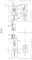
- Fig. 1 is block diagram showing an embodiment of the data collection system based on this invention, in which indicated by 1 is a data collection-transmission unit, 2 is an IC card terminal, 3 is an acoustic coupler, 4 is an IC card, 5 is a telephone set, 6 is a telephone line, 7 is a data reception unit, 8 is a modem (modulator/demodulator), 9 is a work station, 10 is a voice synthesizer, and 11 is a reader/writer.
- 1 is a data collection-transmission unit
- 2 is an IC card terminal
- 3 is an acoustic coupler
- 4 is an IC card
- 5 is a telephone set
- 6 is a telephone line
- 7 is a data reception unit
- 8 is a modem (modulator/demodulator)
- 9 is a work station
- 10 is a voice synthesizer
- 11 is a reader/writer.
- the data collection-transmission unit 1 is made up of the IC card terminal 2, the acoustic coupler 3 and IC card 4.
- the terminal 2 and acoustic coupler 3 may be an integrated unit, or may be formed in units which can be coupled or separated.
- the terminal 2 also serves as a reader/writer for the IC card 4.
- data is entered through the input operation by the user and it is stored in the internal memory which is not shown.
- the data is read out of the memory and fed to the acoustic coupler 3, and after being modulated into an FSK (Frequency Shift Keying) signal, it is formed into an acoustic signal which can be transmitted over the telephone line 6.
- the acoustic coupler 3 has a function of only unidirectional conversion from data to FSK signal.
- the data reception unit 7 is made up of a modem 8 linked to the telephone line 6, a work station 9, a voice synthesizer 10, and a reader/writer 11 for the IC card 4.
- the modem 8 is connected to the telephone line 6, and it operates to demodulate the call signal and FSK signal sent over the telephone line 6 and also receive on its audio input terminal the audio signal produced by the voice synthesizer 10 and send it over the telephone line 6.
- the modem 8 detects it and sends a command to the work station 9.
- the work station 9 is set to the data reception mode.
- the voice synthesizer 10 is controlled by the work station 9 to issue an audio message signal to the user indicative of the admission of data transmission.
- This audio signal is placed on the telephone line 6 through the modem 8. Consequently, the user recognizes the status of data transmission admission through the earphone of the telephone set 5 and can proceed to the transmission of subsequent data by operating the terminal 2, and communication with the data reception unit 7 is now established to have data transmission.
- the sound of data produced by the acoustic coupler 3 is sensed by the telephone set 5, and the data is transmitted as the FSK signal to the data reception unit 7 over the telephone line 6.
- the FSK signal is demodulated by the modem 8 and stored in the work station 9.
- the voice synthesizer 10 equipped in the data reception unit is linked to the telephone line 6 through the modem 8, it is not connected to the telephone line 6 after the modulation by the modulation function in the modulation/demodulation function of the modem 8, but a low-frequency audio signal from the voice synthesizer 10 is connected directly through telephone controllers 8a and 8b which function as the interface with the telephone line 6, as will be clarified by the later explanation on Figs. 8 and 9.
- stored data can be transferred to the IC card 4 which is set on it, allowing backup of data, and stored in the IC card 4 can be moved to the work station 9 by setting the IC card 4 on the reader/writer 11 of the data reception unit 7.
- data entered to the data collection-transmission unit 1 can be transferred to the work station 9 promptly even from a place distant from the data reception unit 7.
- Figs. 2A and 2B show external views of an embodiment of the data collection-transmission unit 1, with the IC card 4 being set on it.
- Fig 2A is a front view and Fig. 2B is a rear view.
- Fig. 3 shows a specific embodiment of the circuit arrangement of the data collection-transmission unit 1, with the terminal 2 being attached to the acoustic coupler 3 or these devices being integrated as a unitary unit.
- 2c is a CPU
- 2d is a memory
- 2e is an IC card controller
- 2f is a display controller
- 2g is a keyboard controller
- 2h is a power source
- 3b is a DTMF (Dual Tone Multi-Frequency) circuit
- 2 is a FSK (Frequency Shift Keying) circuit
- 3d is a switch, with blocks identical to those of the figures which have been referenced being given the common symbols.
- the sections with symbols headed by "2" are equipped in the terminal 2, while the sections with symbols headed by "3" are equipped in the acoustic coupler 3.
- the data collection-transmission unit 1 is carried by a salesman, and order data is entered at each order reception from a customer.
- the order data consists of the costomer's name data, destination data, commodity name data, and quantity data, as shown in Fig. 5.
- the power switch (not shown) of the terminal 2 is turned on so that the voltage from the power source 2h is applied to the circuit, and a menu is read out of the memory 2d and displayed on the display panel 2b thereby to prompt the user to select one of "registration of personal code or confidential number", “data input”, or “data transmission” (step 401).
- a display on the display panel 2b prompts the entry of the personal code (e.g., company's membership code) of the user who uses this data collection-transmission unit 1.
- the personal code e.g., company's membership code
- the confidential number stored in the IC card 4 is effective, and the confidential number registration process of step 403 is skipped.
- step 401 After the foregoing registration for the data collection-transmission unit 1 has been completed and when the salesman intends to enter order data received from a customer, he invokes the menu on the display panel 2b and operates the data entry key on the keyboard 2a to select "data input” (step 401).
- the display controller 2f displays the input prompt for each order data on the display panel 2b in response to the command from the CPU 2c.
- the user operates the keyboard 2a to enter data indicative of the customer's name and destination of the received order (step 404), and subsequently enters the commodity name and quantity of the received order (step 405).
- the input operation is repeated for all commodities of received order until the completion of entry is instructed by the user (step 406).
- the input data are stored in the data storage area of the memory 2d.
- data which is being entered is displayed on the display panel 2b so that the user can check whether or not the data is entered correctly, and the input data is stored in the memory 2d in response to the operation on the keyboard 2a by the user following the check. It is also possible to read out stored data from the memory 2d to the display panel 2b for the confirmation or correction.
- step 407 the user operates the data transmission key on the keyboard 2a to select "data transmission" in the menu displayed on the display panel 2b (step 401). Subsequently, the user operates the keyboard 2a to read out data in the memory 2d to the display panel 2b sequentially thereby to specify data to be sent (step 407).
- This selection can be implemented by setting a flag for date which is to be sent or data which must not be sent. This selection may otherwise be carried out at data entry.
- step 408 the user operates the keyboard 2a to enter the confidential number (step 408), and it is collated with the registered confidential number set in step 403 or the registered confidential number on the IC card 4 (step 409). If both numbers do not match, the user is prompted to retry the entry of confidential number, and if the coincident result is not reached within the prescribed number of retrials, such a process as invalidation of the registered confidential number takes place and the control sequence returns to step 401.
- the collation of confidential number in step 409 is implemented inside the IC card 4 and the result of collation is sent to the CPU 2c by way of the IC card controller 2e.
- Fig. 6 shows the subroutine invoked for this process.
- the subroutine shown in Fig. 6 is initiated to transfer the confidential number from the CPU 2c to the IC card 4 by way of the IC card controller 2e (step 420).
- the display controller 2f displays the prompt of retrial within the prescribed number of times on the display panel 2b by way of the CPU 2c (step 423), and the confidential number is collated again (step 424).
- the control sequence returns to step 422, or in the event of inconsistency, the data collection-transmission unit 1 operates to reject a further access or invalidate the confidential number registered in the IC card 4 in order to protect data stored in the IC card 4 (step 425).
- a message "auto-dial needed?" is displayed on the display panel 2b.
- the user examines whether the telephone set used for data transmission has the ability of auto-dial (generally, a telephone set with a rotary dial is not operative in auto-dial mode, and a telephone set with a push-button dial is operative in auto-dial mode), and in the case of a telephone set without the auto-dial function, the user turns the dial of the telephone set to call the data reception unit 7.
- the user operates the auto-dial key on the keyboard 2a, and the CPU 2c responds to it to operate the DTMF circuit 3b and control the switch circuit 3e to close the switch 3d on the A side.
- the DTMF circuit 3b generates a dial tone signal, which is identical to that generated by the telephone set, indicative of the telephone number of the data reception unit 7.
- the dial tone signal is supplied to the speaker 3a by way of the switch 3d, and an audible acoustic signal is produced accordingly.
- the speaker 3a is placed close to the microphone of the off-hooked telephone handset. Consequently, the acoustic signal is sensed by the telephone set 5, which then produces the same dial tone signal as the one produced by the manual dialing operation thereby to call the data reception unit 7 (step 411).
- the CPU 2c operates on the switch circuit 3e to reverse the switch 3d to the B side and reads the order data, which have been selected in step 407, sequentially from the memory 2d.
- the order data is a binary digital signal formed of "1" bits and "0" bits, and it is fed to the FSK circuit 3c to produce a modulated signal (FSK signal) having a carrier frequency of f 1 for "1" bits or a carrier frequency of f 2 for "0" bits.
- the frequencies f 1 and f 2 are within the transmission band of the telephone line 6.
- the FSK signal is applied to the speaker 3a by way of the switch 3d, and the speaker 3a produces a sound having the frequencies of the FSK signal.
- the speaker 3a is kept close to the microphone of the off-hooked handset of the telephone set 5, and the sound produced by the speaker 3a is introduced to the telephone set 5 and the order data carried by the FSK signal is transmitted over the telephone line 6 (step 412).
- step 413 After the confirmation of the voiced answer-back by the user, if the transmission of order data is not normal (step 413), data transmission will be restart (step 412).
- the personal code registered in the memory 2d is also sent, so that the person pertinent to the order data is made known.
- the IC card 4 functions as a backup means for the memory 2d. Needless to say, the collation of confidential number is implemented with respect to the IC card 4 in this case.
- steps 408,409 Since the confidential number is collated with the IC card 4 as mentioned above at data transmission (steps 408,409), data transmission by other person can be inhibited and illegal data transmission can be prevented.
- the confidential number collating function By executing the confidential number collating function with the IC card 4, which has been illustrated as a subroutine in Fig. 6, before each of steps 402,404 and 407, it is possible to disallow the use of the data collection-transmission unit 1 by other person, whereby the prevention of illegal use of the data collection-transmission unit 1 and the protection of secrecy of data are ensured.
- Fig. 7 has time axes in the vertical direction, on which are shown separately the operations of the data collection-transmission unit 1, telephone set 5, modem 8, work station 9 and voice synthesizer 10, with the order of operations being indicated by numerals enclosed by circles.
- the telephone set 5 In the case of sending out data from the data collection-transmission unit 1, the telephone set 5 is off-hooked at the beginning, and auto-dialing (this is the operation of step 411 in Fig. 4) is carried out thereby to call the data reception unit 7. If the telephone set 5 is of the type without the auto-dial function, the user dials the telephone set 5 manually. Consequently, the modem 8 receives a call signal (reception), and it sends a reception acknowledge signal to the work station 9.
- the work station 9 responds to this signal to enter the data reception mode, and operates on the voice synthesizer 10 to generate an audio signal of a message, e.g., "Send data".
- This audio signal is fed through the modem 8 and transmitted to the telephone set 5 over the telephone line 6.
- the user hears the message on the telephone set 5, and transmits order data in the data collection-transmission unit 1 by using the telephone set 5 over the telephone line 6, as explained for step 412 in Fig. 4.
- the order data is processed by the modem 8 and thereafter introduced to the work station 9.
- the work station 9 On receiving the entire order data correctly, the work station 9 operates on the voice synthesizer 10 to generate an audio signal of a message, e.g., "Received normally", or if it could not introduce order data correctly, it lets the voice synthesizer 10 generate an audio signal of a message, e.g., "Send again".
- the voice synthesizer 10 On receiving the latter message on the telephone set 5, the user takes a recursive order data transmission, or on receiving the former message, the user on-hooks the telephone set 5 to complete the operation.
- the work station 9 can commence the delivery operation for the order immediately, and in consequence delivery of commodity to the customer can be sped up.
- a commercially available model with the setup of the specified carrier frequencies f 1 and f 2 of FSK signal can be used.
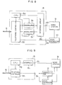
- Fig. 8 shows in brief, as an example, the modem VM-12 having an audio input/output terminal manufactured by Sharp Corp.
- a telephone controller 8b is linked directly to the telephone line 6, and it has the reception wait mode, line connection (off-hook) mode and line disconnection (on-hook) mode switched by the control of a CPU 8a.
- the modem is provided with a digital signal input/output terminal 8f connected to an interface circuit 8d, and an audio signal input/output terminal 8e connected to the telephone controller 8b.
- the CPU 8a activates a demodulation circuit 8c or modulation circuit 8c' depending on the command received on the digital signal input/output terminal 8f.
- the demodulation circuit 8c demodulates the FSK signal, while the modulation circuit 8c' modulates the input digital signal into the FSK signal.
- the work station 9 is connected to the input/output terminal 8f and the voice synthesizer 10 is connected to the audio input/output terminal 8e.
- the modulation circuit 8c' is not used.
- the dial tone signal has its carrier frequencies set to 1080 Hz and 1750 Hz in compliance with the CCITT V21 standard in this case. Accordingly, the foregoing carrier frequencies f 1 and f 2 for the modulation of data by the FSK circuit 3c (Fig. 3) are also set to these frequencies.
- the CPU 8a sets the reception wait mode for the telephone controller 8b in accordance with the modem control signal received from the work station 9 through the interface.
- the dial tone signal is transmitted by the telephone set 5 (Fig. 1) and a call signal comes in by way of the telephone exchange
- the CPU 8a brings the telephone controller 8b to the line connection mode and sends a reception response to the work station 9.
- the work station 9 operates on the voice synthesizer 10 to generate the above-mentioned audio message signal. This audio signal is fed to the modem 8 through the audio input/output terminal 8e, and sent over the telephone line 6 through the telephone controller 8b.
- the order data in the form of the FSK signal is sent to the demodulation circuit 8c through the telephone controller 8b and, after being demodulated by it, sent to the work station 9.
- the work station 9 operates on the voice synthesizer 10 to generate the audio message signal for the response to the normal reception or the request of recursive transmission
- the signal is fed to the modem 8 through the audio input/output terminal 8e and it is sent over the telephone line 6 through the telephone controller 8b.
- the telephone set 5 (Fig. 1) is on-hooked, and in response to an incoming busy-tone signal from the telephone exchange, the CPU 8a brings the telephone controller 8b to the line disconnection mode.
- Fig. 9 shows in brief, as another example of the modem 8 in Fig. 1, the NCU (Network Control Unit), model PNC-3400, manufactured by I/O Data Equipment.
- NCU Network Control Unit
- PNC-3400 manufactured by I/O Data Equipment.
- a telephone controller 8h is linked directly to the telephone line 6, and it has the reception wait mode, line connection mode and line disconnection mode switched by the control of a CPU 8g.
- the CPU 8g is connected to the command input/output terminal 8j through an interface circuit 8i, and the NCU is further provided with an audio input/output terminal 8k connected to the telephone controller 8h.
- the work station 9 is connected through its control terminal to the input/output terminal 8j and the voice synthesizer 10 is connected to the audio input/output terminal 8k.
- the FSK signal demodulator circuit 12 has its input terminal connected to the audio input/output terminal 8k and its output terminal connected to the data terminal of the work station 9.
- the dial tone signal has its carrier frequencies set to 2025 Hz and 2225 Hz in compliance with the BELL 103 standard in this case. Accordingly, the foregoing carrier frequencies f 1 and f 2 of the FSK signal sent from the data collection-transmission unit 1 (Fig. 1) are also set to these frequencies.
- the CPU 8g controls the telephone controller 8h in accordance with the modem control signal which is supplied from the work station 9 through the interface circuit 8e.
- the FSK signal of data sent over the telephone line 6 is supplied from the telephone controller 8h to the demodulator 12, and the demodulated signal is supplied to the work station 9.
- the audio message signal produced by the voice synthesizer 10 is placed on the telephone line 6 by way of the audio input/output terminal 8k and telephone controller 8h.
- the second embodiment is designed such that the memory 2d of the terminal 2 in Fig. 1 can store only order data and the IC card 4 is not used. Accordingly, the IC card controller 2e in Fig. 3 is absent and the personal code registration step 402 in Fig. 4 is absent in this embodiment.
- the data input operation and data transmission operation of this embodiment are virtually identical to those of Fig. 4, and in case the personal code needs to be sent prior to data transmission, the user operates the keyboard 2a to enter the personal code to the terminal 2 and it is converted by the acoustic coupler 3 into a sound signal to be introduced to the telephone set 5.
- the third embodiment is designed such that the memory 2d of the terminal 2 can store order data and also personal code.
- the arrangement is identical to the second embodiment, but this embodiment differs from the second embodiment in that if the personal code is registered in the memory 2d, it is sent automatically at data transmission.
- the fourth embodiment is designed to use a memory card or optical card as an ID card, with the personal code being recorded on it, with the intention of eliminating the need of personal code registration.
- an ID card is set on the terminal 2, which then reads the personal code to enable the transmission.
- the ID card cannot be used to store order data.
- the ID card controller which is equivalent to the IC card controller 2e in Fig. 3 only reads data out of the ID card.
- the fifth embodiment is derived from the fourth embodiment, but order data is stored in the ID card instead of the memory 2d of the terminal 2. At data transmission, the personal code and order data are read out of the ID card.
- the sixth embodiment uses the IC card, and order data is stored in the memory 2d of the terminal 2.
- the personal code is recorded in the IC card in advance, and it is read out and sent at transmission. In this case, the collation with the confidential number of the IC card is necessary at reading out the personal code, and other person cannot read out the personal code.
- the seventh embodiment is derived from the sixth embodiment, but order data is stored in the IC card instead of the memory 2d. At data transmission, the personal code and order data are read out of the IC card and sent.
- the work station 9 it is also possible to register personal codes in the work station 9 so that it introduces transmitted order codes only for legal persons through the collation of personal codes sent from the data collection-transmission unit 1.
- the personal code may have a function of rejecting the entry of illegal data to the work station 9, in addition to the function of distinguishing orders based on person.
- data received by the data reception unit 7 is stored in the work station, it may be stored in other capacious device such as a terminal which is controlled by a large computer.
- voiced messages are produced by using a voice synthesizer board, predetermined signals may be produced by means of a buzzer or the like.
- the foregoing embodiments enable the user to collect necessary data accurately and transmit the collected data to the work station over the telephone line by merely carrying the apparatus of outstanding portability, whereby input data can be transferred to the work station promptly, surely and without error even from a place distant from the work station, the anxiety about the loss of data and the labor of data transaction are eliminated, and the memory capacity needed for data collection can be reduced significantly.
- the data collection-transmission apparatus and the data collection system using the same based on this invention it is possible to transmit data recorded in the portable data collection-transmission unit to the central data reception unit directly based on data communication through the acoustic coupler attached to the data collection-transmission unit for converting data in the unidirectional manner into the signal form of telephone line, and they are useful for data collection from remote places through the telephone line.
Landscapes
- Engineering & Computer Science (AREA)
- General Engineering & Computer Science (AREA)
- Physics & Mathematics (AREA)
- General Physics & Mathematics (AREA)
- Theoretical Computer Science (AREA)
- Signal Processing (AREA)
- Telephonic Communication Services (AREA)
Claims (6)
- Système de collecte de données comprenant :une unité portable (1) de collecte et transmission de données qui comprend :un moyen formant mémoire (2d) pour stocker des données,un moyen d'instruction (2a, 2g) pour entrer des instructions opératoires contenant des instructions d'entrée/sortie de données dans ledit moyen formant mémoire,une unité centrale de traitement (2c) servant à traiter des données entrées et sorties dans ou du moyen formant mémoire en accord avec les instructions opératoires entrées par l'intermédiaire dudit moyen d'instruction, etun coupleur acoustique unidirectionnel (3) contenant un moyen formant circuit de traitement de signal pour convertir des données extraites dudit moyen formant mémoire par ladite unité centrale de traitement en accord avec des instructions opératoires provenant dudit moyen d'instruction en un signal d'entrée de données qui peut être transmis sur une ligne téléphonique (6), et un haut-parleur (3a) réagissant audit signal provenant du moyen formant circuit de traitement de signal, convertissant le signal en un signal acoustique et envoyant le signal acoustique à un combiné téléphonique, etune unité (7) de réception de données qui contient :un moyen de démodulation (8) couplé à ladite ligne téléphonique (6) pour convertir le signal acoustique transmis sur ladite ligne téléphonique en un signal de sortie de données,un moyen (9) formant terminal d'information servant à stocker ledit signal de sortie de données provenant du moyen de démodulation pour juger du résultat des données reçues, etun moyen (10) de synthèse de la parole couplé à ladite ligne téléphonique pour produire un message de réponse synthétisé et coupler ledit message de réponse à ladite unité de collecte et transmission de données sur la ligne téléphonique, en réponse au résultat de jugement des données reçues effectué par ledit moyen formant terminal d'information.
- Système de collecte de données selon la revendication 1, comprenant en outre un circuit (3b) de production de tonalité d'appel, produisant un signal de tonalité d'appel qui représente un certain numéro de téléphone, et un moyen de commutation (3e) servant à choisir, en accord avec l'instruction opératoire venant dudit moyen d'instruction, un signal de tonalité d'appel produit par ledit moyen de production de tonalité d'appel ou le signal d'entrée de données produit par ledit moyen formant circuit de conversion des données et fournir le signal choisi audit haut-parleur (3a).
- Système de collecte de données selon la revendication 1, comprenant en outre une carte de circuits intégrés (CI) amovible, fixée à ladite unité (1) de collecte et transmission de données, ladite unité centrale de traitement (2c) permettant d'entrer et sortir des données avec ladite carte de circuits intégrés et d'échanger des données avec ladite mémoire en accord avec lesdites instructions opératoires fournies par ledit moyen d'instruction.
- Système de collecte de données selon la revendication 1, dans lequel ladite mémoire (2d) de ladite unité (1) de collecte et transmission de données mémorise un code d'identification et ladite unité centrale de traitement (2c) délivre des données extraites de ladite mémoire audit coupleur acoustique unidirectionnel (3) uniquement lorsqu'une information d'entrée, en provenance dudit moyen d'instruction, coïncide avec ledit code d'identification.
- Procédé d'exploitation d'un système de collecte de données comprenant une unité portable (1) de collecte et transmission de données et une unité (7) de réception de données, comprenant les étapes consistant à mémoriser des données dans ladite unité portable de collecte et transmission de données, entrées par un moyen placé dans ladite unité portable de collecte et transmission de données, à composer (411) un certain numéro de téléphone qui correspond à ladite unité de réception de données, à transférer (412) lesdites données de ladite unité portable de collecte et transmission de données à ladite unité de réception de données sur une ligne téléphonique à l'aide d'un coupleur unidirectionnel (3), à recevoir lesdites données en provenance de ladite unité portable de collecte et transmission de données, à juger les données reçues au niveau d'un moyen formant terminal d'information se trouvant dans ladite unité de réception de données, à synthétiser un message en réponse à une condition de réception desdites données reçues avec un moyen de synthèse de la parole et à envoyer le message synthétisé sur ladite ligne téléphonique.
- Procédé selon la revendication 5, comprenant en outre l'étape consistant à entrer et mémoriser un code d'identification dans ladite unité portable de collecte et transmission de données et à comparer une donnée d'instruction entrée dans ladite unité portable de collecte et transmission de données avec ledit code d'identification.
Applications Claiming Priority (3)
| Application Number | Priority Date | Filing Date | Title |
|---|---|---|---|
| JP1265225A JPH03127288A (ja) | 1989-10-13 | 1989-10-13 | データ収集装置およびデータ収集システム |
| JP265225/89 | 1989-10-13 | ||
| PCT/JP1990/001323 WO1991006067A1 (fr) | 1989-10-13 | 1990-10-12 | Dispositif de collecte et de transmission de donnees, et systeme de collecte de donnees |
Publications (3)
| Publication Number | Publication Date |
|---|---|
| EP0451288A1 EP0451288A1 (fr) | 1991-10-16 |
| EP0451288A4 EP0451288A4 (en) | 1992-10-07 |
| EP0451288B1 true EP0451288B1 (fr) | 1998-09-16 |
Family
ID=17414264
Family Applications (1)
| Application Number | Title | Priority Date | Filing Date |
|---|---|---|---|
| EP90914961A Expired - Lifetime EP0451288B1 (fr) | 1989-10-13 | 1990-10-12 | Dispositif et procedure de collecte et de transmission de donnees |
Country Status (3)
| Country | Link |
|---|---|
| EP (1) | EP0451288B1 (fr) |
| JP (1) | JPH03127288A (fr) |
| WO (1) | WO1991006067A1 (fr) |
Families Citing this family (8)
| Publication number | Priority date | Publication date | Assignee | Title |
|---|---|---|---|---|
| JPH04104368U (ja) * | 1991-02-14 | 1992-09-08 | 沖電気工業株式会社 | 携帯用端末 |
| FR2689274A1 (fr) * | 1992-03-26 | 1993-10-01 | Gemplus Card Int | Crayon à détection pour la saisie d'informations et système de saisie comportant un tel crayon. |
| AU729763B2 (en) * | 1992-09-19 | 2001-02-08 | Tunstall Group Plc | Remote activity monitoring system and method |
| GB2301263B (en) * | 1992-09-19 | 1997-04-02 | Tunstall Group Plc | Portable service provision monitoring |
| FR2712102B1 (fr) * | 1993-11-03 | 1996-04-12 | Bruno Robert | Dispositif de saisie d'informations à partir de codes à barres. |
| ATE483217T1 (de) * | 1995-04-28 | 2010-10-15 | Koninkl Kpn Nv | Vorrichtung zur transparenten wechselwirkung zwischen einer chipkarte und einem entfernten endgerät |
| NL1000254C2 (en) * | 1995-04-28 | 1996-10-29 | Nederland Ptt | Data exchange device for IC card and remote terminal |
| US6080064A (en) * | 1996-04-26 | 2000-06-27 | Koninklijke Ptt Nederland N.V. | Device for playing games via a communications network, and a game system using a communications network |
Family Cites Families (9)
| Publication number | Priority date | Publication date | Assignee | Title |
|---|---|---|---|---|
| AU549646B2 (en) * | 1980-09-10 | 1986-02-06 | Porta Printer Systems Inc. | Means of assimilating utility meter data |
| US4503288A (en) * | 1981-08-31 | 1985-03-05 | Novation, Inc. | Intelligent telephone |
| DE3312401C2 (de) * | 1982-04-06 | 1985-06-27 | Sharp K.K., Osaka | Tragbares Dateneingabe- und Datenübertragungsgerät |
| NL8400973A (nl) * | 1983-04-28 | 1984-11-16 | Visa Int Service Ass | Audiotransactiepost met wisselwerking. |
| JPS60180067U (ja) * | 1984-05-08 | 1985-11-29 | 三洋電機株式会社 | デ−タ処理装置 |
| JPS62144456A (ja) * | 1985-12-19 | 1987-06-27 | Canon Inc | デ−タ通信装置 |
| US4799254A (en) * | 1986-06-30 | 1989-01-17 | Wang Laboratories, Inc. | Portable communication terminal for remote database query |
| JPS63255781A (ja) * | 1987-04-13 | 1988-10-24 | Canon Inc | ハンデイタ−ミナル装置 |
| JPS63175266U (fr) * | 1987-04-30 | 1988-11-14 |
-
1989
- 1989-10-13 JP JP1265225A patent/JPH03127288A/ja active Pending
-
1990
- 1990-10-12 EP EP90914961A patent/EP0451288B1/fr not_active Expired - Lifetime
- 1990-10-12 WO PCT/JP1990/001323 patent/WO1991006067A1/fr active IP Right Grant
Also Published As
| Publication number | Publication date |
|---|---|
| EP0451288A1 (fr) | 1991-10-16 |
| EP0451288A4 (en) | 1992-10-07 |
| JPH03127288A (ja) | 1991-05-30 |
| WO1991006067A1 (fr) | 1991-05-02 |
Similar Documents
| Publication | Publication Date | Title |
|---|---|---|
| US5384834A (en) | Telephone apparatus using a detachable memory device | |
| US4677657A (en) | Voice recording card | |
| US5714741A (en) | Device for transparent interaction between an IC card and a remote terminal | |
| US20020193129A1 (en) | Telecommunications system | |
| CN1141710A (zh) | 远程启动蜂窝电话的设备及方法 | |
| US5467475A (en) | Data collection-transmission apparatus and data collection system | |
| JPH0430631B2 (fr) | ||
| WO1991007042A1 (fr) | Appareil de guichet libre service portable | |
| WO1996041461A1 (fr) | Passerelle pour systeme peu onereux d'introduction en teleavertisseur alphanumerique | |
| EP0289590A1 (fr) | Carte de poche a donnees electroniques et systeme et procede de transmissions | |
| JP2002109421A (ja) | 携帯端末を用いた振込方法および振込システム | |
| EP1114549B1 (fr) | Systeme et procede pour l'enregistrement et le traitement d'informations dans un dispositif hertzien | |
| EP0451288B1 (fr) | Dispositif et procedure de collecte et de transmission de donnees | |
| EP0459488B1 (fr) | Appareil de radio-télécommunication | |
| GB2345228A (en) | Radio communication apparatus with telephone number registering function through speech recognition | |
| JPH08307508A (ja) | 国際電話利用装置 | |
| JP3201245B2 (ja) | コードレス電話システム | |
| JPH0345072A (ja) | ファクシミリ装置 | |
| JP3177061B2 (ja) | 通信端末装置 | |
| JP2510957B2 (ja) | 個人別サ―ビス通信システム | |
| CA2193313C (fr) | Methode pour communiquer avec une unite de reponse vocale par le truchement d'un reseau telephonique cellulaire | |
| JP2887093B2 (ja) | データ受信装置 | |
| JPS6314575A (ja) | 自動着信相手先認識方式 | |
| JPH09298588A (ja) | データ送信装置 | |
| JPH11275251A (ja) | ライセンスカードデータ入力装置付電話機 |
Legal Events
| Date | Code | Title | Description |
|---|---|---|---|
| PUAI | Public reference made under article 153(3) epc to a published international application that has entered the european phase |
Free format text: ORIGINAL CODE: 0009012 |
|
| 17P | Request for examination filed |
Effective date: 19910612 |
|
| AK | Designated contracting states |
Kind code of ref document: A1 Designated state(s): FR |
|
| A4 | Supplementary search report drawn up and despatched |
Effective date: 19920820 |
|
| AK | Designated contracting states |
Kind code of ref document: A4 Designated state(s): FR |
|
| 17Q | First examination report despatched |
Effective date: 19950801 |
|
| GRAG | Despatch of communication of intention to grant |
Free format text: ORIGINAL CODE: EPIDOS AGRA |
|
| GRAG | Despatch of communication of intention to grant |
Free format text: ORIGINAL CODE: EPIDOS AGRA |
|
| GRAH | Despatch of communication of intention to grant a patent |
Free format text: ORIGINAL CODE: EPIDOS IGRA |
|
| GRAH | Despatch of communication of intention to grant a patent |
Free format text: ORIGINAL CODE: EPIDOS IGRA |
|
| GRAA | (expected) grant |
Free format text: ORIGINAL CODE: 0009210 |
|
| AK | Designated contracting states |
Kind code of ref document: B1 Designated state(s): FR |
|
| PGFP | Annual fee paid to national office [announced via postgrant information from national office to epo] |
Ref country code: FR Payment date: 19980917 Year of fee payment: 9 |
|
| ET | Fr: translation filed | ||
| PLBE | No opposition filed within time limit |
Free format text: ORIGINAL CODE: 0009261 |
|
| STAA | Information on the status of an ep patent application or granted ep patent |
Free format text: STATUS: NO OPPOSITION FILED WITHIN TIME LIMIT |
|
| 26N | No opposition filed | ||
| PG25 | Lapsed in a contracting state [announced via postgrant information from national office to epo] |
Ref country code: FR Free format text: LAPSE BECAUSE OF NON-PAYMENT OF DUE FEES Effective date: 20000630 |
|
| REG | Reference to a national code |
Ref country code: FR Ref legal event code: ST |