EP0450952B1 - Optische Einrichtung für die Farbbilddarstellung - Google Patents
Optische Einrichtung für die Farbbilddarstellung Download PDFInfo
- Publication number
- EP0450952B1 EP0450952B1 EP91302962A EP91302962A EP0450952B1 EP 0450952 B1 EP0450952 B1 EP 0450952B1 EP 91302962 A EP91302962 A EP 91302962A EP 91302962 A EP91302962 A EP 91302962A EP 0450952 B1 EP0450952 B1 EP 0450952B1
- Authority
- EP
- European Patent Office
- Prior art keywords
- light
- optical
- reading
- polarized light
- liquid crystal
- Prior art date
- Legal status (The legal status is an assumption and is not a legal conclusion. Google has not performed a legal analysis and makes no representation as to the accuracy of the status listed.)
- Expired - Lifetime
Links
- 230000003287 optical effect Effects 0.000 title claims description 75
- 238000000926 separation method Methods 0.000 claims description 21
- 239000004973 liquid crystal related substance Substances 0.000 claims description 17
- 230000010287 polarization Effects 0.000 claims description 14
- 239000003086 colorant Substances 0.000 claims description 12
- 239000002131 composite material Substances 0.000 claims description 5
- 230000000694 effects Effects 0.000 claims description 4
- 239000005264 High molar mass liquid crystal Substances 0.000 claims description 3
- 239000007788 liquid Substances 0.000 claims description 2
- 230000005684 electric field Effects 0.000 description 8
- 238000010276 construction Methods 0.000 description 3
- 238000006243 chemical reaction Methods 0.000 description 2
- RTAQQCXQSZGOHL-UHFFFAOYSA-N Titanium Chemical compound [Ti] RTAQQCXQSZGOHL-UHFFFAOYSA-N 0.000 description 1
- 239000013078 crystal Substances 0.000 description 1
- 230000001419 dependent effect Effects 0.000 description 1
- 238000010586 diagram Methods 0.000 description 1
- 229910052746 lanthanum Inorganic materials 0.000 description 1
- FZLIPJUXYLNCLC-UHFFFAOYSA-N lanthanum atom Chemical compound [La] FZLIPJUXYLNCLC-UHFFFAOYSA-N 0.000 description 1
- GQYHUHYESMUTHG-UHFFFAOYSA-N lithium niobate Chemical compound [Li+].[O-][Nb](=O)=O GQYHUHYESMUTHG-UHFFFAOYSA-N 0.000 description 1
- 238000012986 modification Methods 0.000 description 1
- 230000004048 modification Effects 0.000 description 1
Images
Classifications
-
- G—PHYSICS
- G02—OPTICS
- G02B—OPTICAL ELEMENTS, SYSTEMS OR APPARATUS
- G02B27/00—Optical systems or apparatus not provided for by any of the groups G02B1/00 - G02B26/00, G02B30/00
- G02B27/10—Beam splitting or combining systems
- G02B27/14—Beam splitting or combining systems operating by reflection only
- G02B27/149—Beam splitting or combining systems operating by reflection only using crossed beamsplitting surfaces, e.g. cross-dichroic cubes or X-cubes
-
- G—PHYSICS
- G02—OPTICS
- G02B—OPTICAL ELEMENTS, SYSTEMS OR APPARATUS
- G02B27/00—Optical systems or apparatus not provided for by any of the groups G02B1/00 - G02B26/00, G02B30/00
- G02B27/10—Beam splitting or combining systems
- G02B27/1006—Beam splitting or combining systems for splitting or combining different wavelengths
- G02B27/102—Beam splitting or combining systems for splitting or combining different wavelengths for generating a colour image from monochromatic image signal sources
- G02B27/1026—Beam splitting or combining systems for splitting or combining different wavelengths for generating a colour image from monochromatic image signal sources for use with reflective spatial light modulators
-
- G—PHYSICS
- G02—OPTICS
- G02B—OPTICAL ELEMENTS, SYSTEMS OR APPARATUS
- G02B27/00—Optical systems or apparatus not provided for by any of the groups G02B1/00 - G02B26/00, G02B30/00
- G02B27/10—Beam splitting or combining systems
- G02B27/14—Beam splitting or combining systems operating by reflection only
- G02B27/145—Beam splitting or combining systems operating by reflection only having sequential partially reflecting surfaces
-
- H—ELECTRICITY
- H04—ELECTRIC COMMUNICATION TECHNIQUE
- H04N—PICTORIAL COMMUNICATION, e.g. TELEVISION
- H04N9/00—Details of colour television systems
- H04N9/12—Picture reproducers
- H04N9/31—Projection devices for colour picture display, e.g. using electronic spatial light modulators [ESLM]
- H04N9/3102—Projection devices for colour picture display, e.g. using electronic spatial light modulators [ESLM] using two-dimensional electronic spatial light modulators
- H04N9/312—Driving therefor
Definitions
- the present invention relates to an optical system for a color picture display.
- a known color picture display such as disclosed in "SID International Symposium Digest of Technical Papers", pp. 379-382, 1986, Palisade Institute for Research Service Inc., and also in DE 3829598 illuminates three spatial light modulators of the reflecting type which receive optical images obtained by subjecting a color picture to be displayed to color separation as writing lights, respectively, by reading lights of different wavelengths in predetermined wavelength bands, respectively, transmitted through a dichroic mirror, and composes the reading lights reflected by the three spatial light modulators of the reflecting type by the dichroic mirror to display the color picture.
- This known color picture display produces the reading lights of different wavelengths in the predetermined wavelength bands, respectively, to be applied to the three spatial light modulators of the reflecting type by the dichroic mirror, and displays the color picture by composing the reading lights reflected by the three spatial light modulators of the reflecting type by the dichroic mirror.
- the color picture display has a comparatively large construction.
- an optical system for a colour picture display having three optical devices (SLM) each including a photoconductive member (PCL) in which an optical image of one of three primary colours is written as a charge image by photoelectric effect and a photomodulation member having a liquid crystal which reproduces the optical image by photomodulation of said liquid crystal, writing means for guiding writing lights each carrying an optical image of one of the colours to each device, a light source , optical means having first, second and third prisms a first dichroic filter provided between the first and second prisms and a second dichroic filter provided between the second and the third prisms for decomposing the light from said light into three reading lights each in a region of wavelength of one of the colours and guiding respectively the reading lights to each device and for composing a reading light composed of the reading lights which are emitted from the devices respectively after being optically modulated by said liquid crystal, characterized by
- an optical system for a colour picture display having three optical devices each including a photoconductive member in which an optical image of one of three primary colours is written as a charge image by photoelectric effect and a photomodulation member having a liquid crystal which reproduces the optical image by photomodulation of said liquid crystal, writing means for guiding writing lights each carrying an optical image of one of the colours to each device, a light source , optical means comprising a three colour separation prism for decomposing the light from the light source into three reading lights each in a region of wavelength of one of the colours and means for guiding respectively the reading lights to each device and for composing a reading light composed of the reading lights which are emitted from the devices respectively after being optically modulated by said liquid crystal, characterized by said liquid crystal being of a composite polymer-liquid type operating in the scattering mode,
- the optical system of the invention doubles the fraction of useful reading light, with regards previous embodiments of the optical system which used a semi-transparent mirror for the purpose.
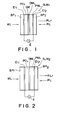
- Spatial light modulators SLM 1 and SLM 2 each comprise electrodes Et1 and Et2, a photoconductive layer PCL, a dielectric mirror layer DML for reflecting a reading light RL, and a photomodulation layer PML, such as a layer of a single crystal of lithium niobate, a liquid crystal layer, a composite polymer-liquid crystal film, PLZT (Lead Lanthanum Zirconate Titanate) or another layer such as these.
- a shading film SM to shade the read side from a writing light WL for writing an optical image as a charge image on the microchannel spatial light modulator SLM 1 and to shade the write side from a reading light RL for reading the charge image formed on the spatial light modulator SLM 1 .
- the electrode Et1 is capable of transmitting the writing light WL
- the electrode Et2 is capable of transmitting the reading light RL.
- each of the spatial light modulators SLM 1 and SLM 2 shown in Figs. 1 and 2 are connected to a power supply E to apply an electric field across the photoconductive layer PCL, and the writing light WL is projected on the electrode Et1, the writing light WL travels through the electrode Et1 and falls on the photoconductive layer PCL.
- the electrical resistance of the photoconductive layer PCL is dependent on the intensity of the writing light WL. Therefore, in the spatial light modulator SLM 1 or SLM 2 shown in Figs. 1 and 2, the image of a resistivity distribution corresponding to the intensity distribution of the writing light WL applied to the photoconductive layer PCL is formed in the photoconductive layer PCL. Thus, an effective electric field is applied to the photomodulation layer PML which varies in accordance with an image applied to the photoconductive layer PCL.
- the reading light RL is reflected by the dielectric mirror DML, transmitted again through the photomodulation layer PML, and then emitted from the electrode Et2.
- a reading light RLr resulting from the change of the plane of polarization of the reading light (linearly polarized light) RL according to the effective electric field applied to the photomodulation layer PML, is emitted from the electrode Et2.
- a reading light RLr resulting from the change of the intensity of the reading light RL (which may be a randomly polarized light) according to the effective electric field applied to the photomodulation layer PML, is emitted from the electrode Et2.
- the condition of the reading light RLr emitted from the electrode Et2 changes according to the effective electric field applied to the photomodulation layer PML, which effective electric field results from the change of the resistivity induced in the photoconductive layer PCL by the writing light WL.
- SLMr In each of Figs. 3 to 6, indicated by SLMr, SLMg and SLMb are spatial light modulators of the reflecting type (light-to-light conversion elements).
- the suffixes "r", “g” and “b” indicate the correspondence of the spatial light modulators respectively with a red image, a green image and a blue image of an optical image to be displayed written in the spatial light modulators by the writing light WL.
- the spatial light modulators SLMr, SLMg and SLMb are denoted inclusively by SLM if described without distinction.
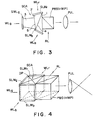
- the optical system shown in Fig. 3 is provided with a three-color separation optical system.
- the three-color separation optical system is a three-color separation prism SCA of a known configuration comprising three prisms 1, 2 and 3, a dichroic filter 4 provided in the interface between the prism 1 and the prism 2, and a dichroic filter 5 provided in the interface between the prisms 2 and 3.
- a reading light RL is projected from a light source onto the prism 1 through the polarizing beam splitter PBS or the semitransparent mirror HMP.
- the polarizing beam splitter PBS receives the reading light RL and a linearly polarized light thereof having a specific plane of polarization (S-polarized light) is reflected there and incident to the prism 1.
- P-polarized light described later is a linearly polarized light of which the plane of polarization is perpendicular to the plane of incidence of the light before the conversion
- S-polarized light is a linearly polarized light of which the plane of polarization is perpendicular to the P-polarized light.
- a light of wavelength in the region of green (hereinafter called a green light) included in the linearly polarized light is transmitted through both the dichroic filters 4 and 5 and falls on the spatial light modulator SLMg provided on the end surface of the prism 3.
- a light of wavelength in the region of red (hereinafter called a red light) included in the linearly polarized light is transmitted through the dichroic filter 4, is reflected by the dichroic filter 5 and falls on the spatial light modulator SLMr provided on the end surface of the prism 2.
- a light of wavelength in the region of blue (hereinafter called a blue light) included in the linearly polarized light RL is reflected by the dichroic filter 4 and falls on the spatial light modulator SLMb provided on the end surface of the prism 1.
- the planes of polarization of the red, green and blue lights respectively outgoing from the spatial light modulators SLMr, SLMg and SLMb are changed by electric fields created by the charge images written in the spatial light modulators SLMr, SLMg and SLMb, respectively while the red, green and blue lights are incident to the photomodulation layers PML of the spatial light modulators SLMr, SLMg and SLMb, respectively.
- the red light outgoing from the spatial light modulator SLMr is reflected by the dichroic filter 5, is transmitted through the dichroic filter 4 and falls on the polarizing beam splitter PBS, and then the P-polarized component of the red light is transmitted through the polarizing beam splitter PBS and falls on a projection lens PJL.
- the green light outgoing from the spatial light modulator SLMg is transmitted through both the dichroic filters 5 and 4 and falls on the polarizing beam splitter PBS, and then the P-polarized component of the green light is transmitted through the polarizing beam splitter PBS and falls on the projection lens PJL.
- the blue light outgoing from the spatial light modulator SLMb is reflected by the dichroic filter 4 and falls on the polarizing beam splitter PBS, and then the P-polarized component of the blue light is transmitted through the polarizing beam splitter PBS and falls on the projection lens PJL.
- the composed light has undergone the intensity changing action of the polarizing beam splitter PBS and is projected on a screen as an optical image corresponding to the color picture.
- a randomly polarized light is used as the read light RL and a semitransparent mirror HMP is used instead of the polarizing beam splitter PBS adopted in the case of a polarized reading light.
- a green light included in the randomly polarized light reflected by the semitransparent mirror HMP toward the prism 1 is transmitted through both the dichroic filters 4 and 5 and falls on the spatial light modulator SLMg provided on the end surface of the prism 3.
- a red light included in the randomly polarized light is transmitted through the dichroic filter 4, is reflected by the dichroic filter 5 and falls on the spatial light modulator SLMr provided on the end surface of the prism 2.
- a blue light included in the randomly polarized light is reflected by the dichroic filter 4 and falls on the spatial light modulator SLMb provided on the end surface of the prism 1.
- the spatial light modulators SLMr, SLMg and SLMb Since charge images corresponding respectively to red, green and blue optical images of the color picture are written in the spatial light modulators SLMr, SLMg and SLMb by writing lights Wr, Wg and Wb, the spatial light modulators SLMr, SLMg and SLMb provide lights modulated by the picture information written as the charge images when the red, green and blue lights are respectively projected on the spatial light modulators SLMr, SLMg and SLMb by the three-color separation prism SCA.
- the respective intensities of the red, green and blue lights provided by the spatial light modulators SLMr, SLMg and SLMb are changed by electric fields created by the electrostatic latent images written in the SLMr, SLMg and SLMb while the red, green and blue lights are incident to the photo modulation layers PML of the spatial light modulators SLMr, SLMg and SLMb, respectively.
- the red light outgoing from the spatial light modulator SLMr is reflected by the dichroic filter 5, is transmitted through the dichroic filter 4 and falls on the semitransparent mirror HMP, and then a component of the red light transmitted through the semitransparent mirror HMP falls on the projection lens PJL.
- the green light outgoing from the spatial light modulator SLMg is transmitted through both the dichroic filters 5 and 4 and falls on the semitransparent mirror HMP, and then a component of the green light transmitted through the semitransparent mirror HMP falls on the projection lens PJL.
- the blue light outgoing from the spatial light modulator SLMb is reflected by the dichroic filter 4 and falls on the semitransparent mirror HMP, and then a component of the blue light transmitted through the semitransparent mirror HMP falls on the projection lens PJL.
- the composed light is projected on the screen in an optical image corresponding to the color picture.
- Optical systems shown in Figs. 4 and 5 for a color picture display are the same in construction as the optical system shown in Fig. 3, except that a three-color separation prism SCA employed as the color separation optical systems shown in Figs. 4 and 5 is different from the three-color separation prism employed in the optical system shown in Figs. 3.
- the three-color separation prism SCA employed as the color separation optical system shown in Fig. 4 comprises a dichroic prism DP.
- the reading light RL transmitted through a polarizing beam splitter PBS or a semitransparent mirror HMP and fallen on the dichroic prism DP is separated into red, green and blue lights by the dichroic prism DP.
- the red, green and blue lights fall on the spatial light modulators SLMr, SLMg and SLMb, respectively.
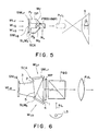
- the optical system shown in Fig. 5 for a color picture display employs the three-color separation prism SCA as the color separation optical system comprising a dichroic prism DP and light path length correction prisms Pr and Pb.
- SCA the color separation optical system comprising a dichroic prism DP and light path length correction prisms Pr and Pb.
- Mr and Mb are total reflection surfaces.
- the dichroic prism DP separates the reading light RL transmitted through a polarizing beam splitter PBS or a semitransparent mirror HMP into red, green and blue lights.
- the red light falls through the prism Pr on the spatial light modulator SLMr, the green light falls on the spatial light modulator SLMg, and the blue light falls through the prism Pb on the spatial light modulator SLMb.
- the three-color separation prism SCA functions satisfactorily in reading image information from the three spatial light modulators SLMr, SLMg and SLMb arranged side by side on a plane.
- the mode of picture information read operation of the optical systems shown in Figs.4 and 5 by using the reading light RL when the spatial light modulators SLMr, SLMg and SLMb act in the double refraction mode, and the mode of picture information read operation of the optical systems shown in Figs.4 and 5 by using the reading light RL when the spatial light modulators SLMr, SLMg and SLMb act in the scattering mode are the same as the modes of picture information read operation of the optical system shown in Fig.3 by using the reading light RL under the same operating modes of the spatial light modulators SLMr, SLMg and SLMb, respectively, and hence the description thereof will be omitted.
- the optical system of the invention shown in Fig. 6 for a color picture display comprises a polarizing beam splitter PBS, a three-color separation prism SCA having prisms 1, 2 and 3, a quarter waveplate WP provided between the polarizing beam splitter PBS and the prism 1, and spatial light modulators SLMr SLMg and SLMb that act in the scattering mode.
- the optical system shown in Fig. 3 employs the semitransparent mirror HMP when the spatial light modulators SLMr, SLMg and SLMb act in the scattering mode, and hence only a quarter of the quantity of light applied to the semitransparent mirror HMP by the light source is used effectively.
- the optical system shown in Fig. 6 employs the polarizing beam splitter PBS to improve such a disadvantage.
- a linearly polarized reading light having a specific plane of polarization (S-polarized light) is reflected toward and falls on the quarter wave plate WP.
- a circularly polarized reading light transmitted through the quarter wave plate WP falls on the prism 1.
- a green light included in the circularly polarized reading light is transmitted through dichroic filters 4 and 5 and falls on the spatial light modulator SLMg provided on the end surface of the prism 3.
- a red light included in the circularly polarized reading light is transmitted through the dichroic filter 4, is reflected by the dichroic filter 5 and falls on the spatial light modulator SLMr provided on the end surface of the prism 2.
- a blue light included in the circularly polarized reading light is reflected by the dichroic filter 4 and falls on the spatial light modulator SLMb provided on the end surface of the prism 1.
- the spatial light modulators SLMr, SLMg and SLMb Since images respectively corresponding to the red, green and blue optical images of a color picture are written in the spatial light modulators SLMr, SLMg and SLMb, which act in the scattering mode, by writing lights Wr, Wg and Wb, respectively, the spatial light modulators SLMr, SLMg and SLMb provide circularly polarized reading lights of intensities modulated according to picture information written in the spatial light modulators SLMr, SLMg and SLMb upon the reception of the red, green and blue lights, respectively.
- the circularly polarized red light provided by the spatial light modulator SLMr is reflected by the dichroic filter 5, is transmitted through the dichroic filter 4, is converted into a P-polarized light by the quarter wave plate WP, travels through the polarizing beam splitter PBS and falls on a projection lens PJL.
- the circularly polarized green light provided by the spatial light modulator SLMg is transmitted through both the dichroic filters 5 and 4, is converted into a P-polarized light by the quarter wave plate WP, travels through the polarizing beam splitter PBS and falls on the projection lens PJL.
- the circularly polarized blue light provided by the spatial light modulator SLMb is reflected by the dichroic filter 4, is converted into a P-polarized light by the quarter wave plate WP travels through the polarizing beam splitter PBS and falls on the projection lens PJL.
- the efficiency of utilization of the reading light RL emitted by the light source LS in the optical system shown in Fig. 6 is twice as large as the efficiency of utilization of the reading light RL in the optical system shown in Fig. 3 provided with the spatial light modulators SLMr, SLMg and SLMb which act in the scattering mode, and the semitransparent mirror HMP for dividing the reading light RL.
Landscapes
- Physics & Mathematics (AREA)
- General Physics & Mathematics (AREA)
- Optics & Photonics (AREA)
- Engineering & Computer Science (AREA)
- Multimedia (AREA)
- Signal Processing (AREA)
- Liquid Crystal (AREA)
- Projection Apparatus (AREA)
Claims (2)
- Ein optisches System für die Farbbildanzeige mit drei optischen Einrichtungen (SLM) von denen jede aufweist: ein photoleitfähiges Element (PCL) auf welches mittels des photoelektrischen Effekts ein optisches Bild in einer der drei Grundfarben als Ladungsbild aufgezeichnet wird und ein Photomodulationselement (PML) mit einem Flüssigkristall, welches das optische Bild mittels der Photomodulation dieses Flüssigkristalls wiedergibt, Schreibeinrichtungen (WL) für das Führen des Schreiblichts, von denen jede ein optisches Bild in einer der Farben auf jede Einrichtung überträgt, eine Lichtquelle (RL), optische Einrichtungen (SCA) die erste, zweite und dritte Prismen (1, 2 und 3) aufweisen, einen ersten dichroitischen Filter (4) der zwischen dem ersten und zweiten Prisma (1 und 2) angeordnet ist und einen zweiten dichroitischen Filter (5) der zwischen dem zweiten und dritten Prisma (2 und 3) angeordnet ist, für die Zerlegung des Lichtes der Lichtquelle in drei Leselichter, jedes im Bereich der Wellenlänge von einer der Farben, beziehungsweise für die Führung der Leselichter zu jeder Einrichtung (SLM) und für das Zusammensetzen eines Leselichtes, welches aus den Leselichtern zusammengesetzt ist, die von den jeweiligen Einrichtungen ausgestrahlt werden nachdem sie mittels des Flüssigkristalls optisch moduliert wurden,
gekennzeichnet durch,den Flüssigkristall der von der Art eines Komposit-Polymer-Flüssigkristalls ist, der im Streumode arbeitet,Strahlteilereinrichtungen (PBS) die nur das S-polarisierte Licht des Lichtes reflektieren, das von der Lichtquelle in Richtung auf die optischen Einrichtungen ausgestrahlt wird, undStrahltrenneinrichtungen (WP) für das Drehen der Polarisationsebene des polarisierten Lichtes, welches von den Strahlteilereinrichtungen in Richtung auf die optischen Einrichtungen reflektiert wird, bevor das S-polarisierte Licht, das von dem Strahlteiler reflektiert wird, von den optischen Einrichtungen zerlegt wird, wobei das S-polarisierte Licht somit zu einem zirkular polarisierten Licht wird, und für das Drehen der Polarisationsebene des Leselichtes, welches durch die optischen Einrichtungen zusammengesetzt wird, wobei das zusammengesetzte Licht somit zu einem P-polarisierten Licht wird. - Ein optisches System für die Farbbildanzeige mit drei optischen Einrichtungen (SLM) von denen jede aufweist: ein photoleitfähiges Element (PCL) auf welches mittels des photoelektrischen Effekts ein optisches Bild in einer der drei Grundfarben als Ladungsbild aufgezeichnet wird und ein Photomodulationselement (PML) mit einem Flüssigkristall, welches das optische Bild mittels der Photomodulation dieses Flüssigkristalls wiedergibt, Schreibeinrichtungen (WL) für das Führen des Schreiblichts, von denen jede ein optisches Bild in einer der Farben auf jede Einrichtung überträgt, eine Lichtquelle (RL), optische Einrichtungen (SCA) die aus einem Drei-Farben-Trennprisma (SCA) bestehen, wobei ein dichroitisches Prisma für die Zerlegung des Lichtes der Lichtquelle in drei Leselichter, jedes im Bereich der Wellenlänge von einer der Farben, eingeschlossen ist, beziehungsweise für die Führung der Leselichter zu jeder Einrichtung (SLM) und für das Zusammensetzen eines Leselichtes, welches aus den Leselichtern zusammengesetzt ist, die von den jeweiligen Einrichtungen ausgestrahlt werden nachdem sie mittels des Flüssigkristalls optisch moduliert wurden,
gekennzeichnet durch,den Flüssigkristall der von der Art eines Komposit-Polymer-Flüssigkristalls ist, der im Streumode arbeitet,Strahlteilereinrichtungen (PBS) die nur das S-polarisierte Licht des Lichtes reflektieren, das von der Lichtquelle in Richtung auf die optischen Einrichtungen ausgestrahlt wird, undStrahltrenneinrichtungen (WP) für das Drehen der Polarisationsebene des polarisierten Lichtes, welches von den Strahlteilereinrichtungen in Richtung auf die optischen Einrichtungen reflektiert wird, bevor das S-polarisierte Licht das von den Strahlteilereinrichtungen reflektiert wird, von den optischen Einrichtungen zerlegt wird, wobei das S-polarisierte Licht somit zu einem zirkular polarisierten Licht wird, und für das Drehen der Polarisationsebene des Leselichtes, welches durch die optischen Einrichtungen zusammengesetzt wird, wobei das zusammengesetzte Licht somit zu einem P-polarisierten Licht wird.
Applications Claiming Priority (2)
| Application Number | Priority Date | Filing Date | Title |
|---|---|---|---|
| JP89777/90 | 1990-04-04 | ||
| JP2089777A JPH03288124A (ja) | 1990-04-04 | 1990-04-04 | カラー画像表示装置の光学系 |
Publications (3)
| Publication Number | Publication Date |
|---|---|
| EP0450952A2 EP0450952A2 (de) | 1991-10-09 |
| EP0450952A3 EP0450952A3 (en) | 1992-06-03 |
| EP0450952B1 true EP0450952B1 (de) | 1996-08-28 |
Family
ID=13980109
Family Applications (1)
| Application Number | Title | Priority Date | Filing Date |
|---|---|---|---|
| EP91302962A Expired - Lifetime EP0450952B1 (de) | 1990-04-04 | 1991-04-04 | Optische Einrichtung für die Farbbilddarstellung |
Country Status (4)
| Country | Link |
|---|---|
| US (1) | US5130826A (de) |
| EP (1) | EP0450952B1 (de) |
| JP (1) | JPH03288124A (de) |
| DE (1) | DE69121620T2 (de) |
Families Citing this family (45)
| Publication number | Priority date | Publication date | Assignee | Title |
|---|---|---|---|---|
| US5264951A (en) * | 1990-04-09 | 1993-11-23 | Victor Company Of Japan, Ltd. | Spatial light modulator system |
| DE69123288T2 (de) * | 1990-05-21 | 1997-04-24 | Victor Company Of Japan | Anzeigegerät |
| FR2669440B1 (fr) * | 1990-11-21 | 1994-08-26 | Sextant Avionique | Dispositif de visualisation en couleur par projection mettant en óoeuvre des valves optiques. |
| GB2252172A (en) * | 1991-01-25 | 1992-07-29 | Rank Brimar Ltd | Colour optical output system |
| DE69228867T2 (de) * | 1991-01-25 | 2000-01-05 | Digital Projection Ltd., Middleton | System mit raumlichem lichtmodulator für ein optisches farbausgangssignal |
| JP2592646Y2 (ja) * | 1991-06-26 | 1999-03-24 | 日本ビクター株式会社 | 投射型表示装置 |
| JP2985906B2 (ja) * | 1991-07-17 | 1999-12-06 | 日本ビクター株式会社 | 投射型表示装置 |
| US5325137A (en) * | 1991-08-28 | 1994-06-28 | Victor Company Of Japan, Ltd. | Overhead projector with a spatial light modulator |
| US5285268A (en) * | 1991-12-10 | 1994-02-08 | Victor Company Of Japan, Ltd. | Projection type display device having a mask for cutting off unnecessary light parts of displayed picture |
| GB9204798D0 (en) * | 1992-03-05 | 1992-04-15 | Rank Brimar Ltd | Spatial light modulator system |
| JPH0579530U (ja) * | 1992-03-24 | 1993-10-29 | 日本ビクター株式会社 | 表示装置の光学系 |
| JPH08510333A (ja) * | 1993-03-31 | 1996-10-29 | ヒューズ − ジェイブイシー テクノロジー コーポレイション | 単一投影レンズのカラー投影システム |
| US5624174A (en) * | 1993-08-25 | 1997-04-29 | Kopin Corporation | Display panel mount for projection display system |
| US5455678A (en) * | 1993-08-25 | 1995-10-03 | Kopin Corporation | Method for mounting light valves for projection display system |
| US5653522A (en) * | 1993-08-25 | 1997-08-05 | Kopin Corporation | Display panel mount for projection dislay system |
| DE4435450A1 (de) * | 1993-10-04 | 1995-04-06 | Matsushita Electric Industrial Co Ltd | Flüssigkristalleinheit und Projektionsanzeige unter Verwendung einer Flüssigkristalleinheit |
| US5526145A (en) * | 1994-06-10 | 1996-06-11 | E. I. Du Pont De Nemours And Company | Color tuned holographic optical elements and methods of making and using the elements |
| EP1376164B1 (de) * | 1994-06-10 | 2009-07-29 | E.I. Du Pont De Nemours And Company | Holographische mehrfarbige optische Elemente zur Verwendung in Flüssigkristallanzeigen und Methoden zu deren Herstellung |
| US5716122A (en) * | 1994-08-25 | 1998-02-10 | Nikon Corporation | Optical apparatus using polarizing beam splitter |
| JP3402527B2 (ja) * | 1994-10-28 | 2003-05-06 | セイコーインスツルメンツ株式会社 | 反射型カラー画像投影装置 |
| US5594591A (en) * | 1995-02-01 | 1997-01-14 | Pioneer Electronic Corporation | Prism system and a liquid crystal projection device |
| US6227670B1 (en) * | 1995-03-06 | 2001-05-08 | Nikon Corporation | Projection type display apparatus |
| DE69611561T2 (de) * | 1995-03-23 | 2001-06-21 | International Business Machines Corp., Armonk | Wirksames optisches System für eine hochauflösende Projektionsanzeige mit Reflexionslichtventilen |
| EP0734182B1 (de) * | 1995-03-23 | 2001-01-17 | International Business Machines Corporation | Wirksames optisches System für eine hochauflösende Projektionsanzeige mit Reflexionslichtventilen |
| EP0734184B1 (de) * | 1995-03-23 | 2001-01-17 | International Business Machines Corporation | Wirksames optisches System für eine hochauflösende Projektionsanzeige mit Reflexionslichtventilen |
| EP0824829B1 (de) * | 1995-05-11 | 2003-02-12 | Digital Projection Limited | Projektionsvorrichtung |
| DE69530425T2 (de) * | 1995-05-29 | 2003-12-18 | International Business Machines Corp., Armonk | Flüssigkristallanzeige und herstellungsverfahren dafür |
| US5621486A (en) * | 1995-06-22 | 1997-04-15 | International Business Machines Corporation | Efficient optical system for a high resolution projection display employing reflection light valves |
| US5897190A (en) * | 1995-09-13 | 1999-04-27 | Victor Company Of Japan, Ltd. | Illumination optical system, projection optical system and display apparatus using the same |
| US6082863A (en) * | 1996-08-16 | 2000-07-04 | Raychem Corporation | Color projection prism |
| CN1231103A (zh) | 1997-05-07 | 1999-10-06 | 皇家菲利浦电子有限公司 | 图像投影系统 |
| JPH10312034A (ja) * | 1997-05-13 | 1998-11-24 | Pioneer Electron Corp | 投写型画像表示装置 |
| US6010221A (en) * | 1997-05-22 | 2000-01-04 | Nikon Corporation | Projection type display apparatus |
| US5951135A (en) * | 1997-10-14 | 1999-09-14 | Raychem Corporation | Color image projection system |
| US7023602B2 (en) * | 1999-05-17 | 2006-04-04 | 3M Innovative Properties Company | Reflective LCD projection system using wide-angle Cartesian polarizing beam splitter and color separation and recombination prisms |
| US5986815A (en) * | 1998-05-15 | 1999-11-16 | Optical Coating Laboratory, Inc. | Systems, methods and apparatus for improving the contrast ratio in reflective imaging systems utilizing color splitters |
| US6398364B1 (en) | 1999-10-06 | 2002-06-04 | Optical Coating Laboratory, Inc. | Off-axis image projection display system |
| JP3858723B2 (ja) * | 2002-02-26 | 2006-12-20 | 株式会社日立製作所 | 光学ユニット及びそれを用いた投射型プロジェクタ装置 |
| US7746681B2 (en) | 2005-01-07 | 2010-06-29 | Invisage Technologies, Inc. | Methods of making quantum dot films |
| US7773404B2 (en) | 2005-01-07 | 2010-08-10 | Invisage Technologies, Inc. | Quantum dot optical devices with enhanced gain and sensitivity and methods of making same |
| US7326908B2 (en) | 2004-04-19 | 2008-02-05 | Edward Sargent | Optically-regulated optical emission using colloidal quantum dot nanocrystals |
| US7742322B2 (en) | 2005-01-07 | 2010-06-22 | Invisage Technologies, Inc. | Electronic and optoelectronic devices with quantum dot films |
| US7347558B2 (en) * | 2004-07-12 | 2008-03-25 | Lightmaster Systems, Inc. | 3D kernel and prism assembly design |
| CN100434972C (zh) * | 2004-07-16 | 2008-11-19 | 台达电子工业股份有限公司 | 分色棱镜组 |
| CA2519608A1 (en) | 2005-01-07 | 2006-07-07 | Edward Sargent | Quantum dot-polymer nanocomposite photodetectors and photovoltaics |
Family Cites Families (16)
| Publication number | Priority date | Publication date | Assignee | Title |
|---|---|---|---|---|
| NL7400148A (nl) * | 1974-01-07 | 1975-07-09 | Philips Nv | Kleurensplitsend prismastelsel met enige opper- en die aan dichroitische lagen grenzen. |
| US4461542A (en) * | 1981-12-28 | 1984-07-24 | Hughes Aircraft Company | High efficiency optical tank for three color liquid crystal light valve image projection with color selective prepolarization |
| US4904061A (en) * | 1984-10-22 | 1990-02-27 | Seiko Epson Corporation | Projection-type liquid crystal display device with even color |
| US4690526A (en) * | 1985-09-12 | 1987-09-01 | Hughes Aircraft Company | Prism assembly for a single light valve full-color projector |
| DE3751233T2 (de) * | 1986-10-31 | 1995-08-24 | Seiko Epson Corp | Anzeigevorrichtung vom Projektionstyp. |
| US4989076A (en) * | 1987-01-27 | 1991-01-29 | Canon Kabushiki Kaisha | Video projection apparatus |
| US4786146A (en) * | 1987-02-11 | 1988-11-22 | Hughes Aircraft Company | Color sequential illumination system for a liquid crystal light valve |
| DE3852776T2 (de) * | 1987-04-14 | 1995-06-22 | Seiko Epson Corp | Projektions-Farbflüssigkristall-Anzeigevorrichtung. |
| DE3720375A1 (de) * | 1987-06-19 | 1988-12-29 | Fraunhofer Ges Forschung | Projektionsvorrichtung |
| JPS6468190A (en) * | 1987-09-09 | 1989-03-14 | Victor Company Of Japan | Three-color separation optical system |
| US5272552A (en) * | 1988-05-11 | 1993-12-21 | Canon Kabushiki Kaisha | Optical modulation device and method using modulation layer of helical polymer liquid crystal having a helical chiral smectic C phase |
| DE3829598A1 (de) * | 1988-08-29 | 1990-03-01 | Hertz Inst Heinrich | Projektionsgeraet |
| JPH0283534A (ja) * | 1988-09-20 | 1990-03-23 | Seiko Epson Corp | 画像形成装置 |
| NL8802517A (nl) * | 1988-10-13 | 1990-05-01 | Philips Nv | Beeldprojektie-inrichting. |
| JPH02143778A (ja) * | 1988-11-25 | 1990-06-01 | Victor Co Of Japan Ltd | 電荷潜像の読取り方式 |
| US5067799A (en) * | 1989-12-27 | 1991-11-26 | Honeywell Inc. | Beam combining/splitter cube prism for color polarization |
-
1990
- 1990-04-04 JP JP2089777A patent/JPH03288124A/ja active Pending
-
1991
- 1991-04-03 US US07/679,602 patent/US5130826A/en not_active Expired - Lifetime
- 1991-04-04 EP EP91302962A patent/EP0450952B1/de not_active Expired - Lifetime
- 1991-04-04 DE DE69121620T patent/DE69121620T2/de not_active Expired - Fee Related
Also Published As
| Publication number | Publication date |
|---|---|
| EP0450952A3 (en) | 1992-06-03 |
| EP0450952A2 (de) | 1991-10-09 |
| JPH03288124A (ja) | 1991-12-18 |
| DE69121620D1 (de) | 1996-10-02 |
| DE69121620T2 (de) | 1997-01-16 |
| US5130826A (en) | 1992-07-14 |
Similar Documents
| Publication | Publication Date | Title |
|---|---|---|
| EP0450952B1 (de) | Optische Einrichtung für die Farbbilddarstellung | |
| JP3060049B2 (ja) | 画像投射装置 | |
| KR900000333B1 (ko) | 3색 액정 광 밸브 영상 프로젝터용 광학시스템 | |
| US4425028A (en) | High efficiency optical tank for three color liquid crystal light valve image projection with color selective prepolarization and single projection lens | |
| JP3480702B2 (ja) | 反射型光バルブ用投影表示システム | |
| US5363222A (en) | Compact optical system for a single light valve full-color projector | |
| EP0301065B1 (de) | Farbsequentielles beleuchtungssystem für ein flüssigkristall-lichtventil | |
| US4464019A (en) | Two-color liquid crystal light valve image projection system with color selective prepolarizers in single optical tank | |
| JPH0579530U (ja) | 表示装置の光学系 | |
| JP4637370B2 (ja) | 変調カラー画像を形成するための光学システム | |
| CA1218546A (en) | High efficiency optical system for three-color liquid crystal light valve image projection with color selective prepolarization | |
| US4842374A (en) | Unitary prepolarizing prism assembly for a four color liquid crystal light valve image projector | |
| JP2001305483A (ja) | 照明光学装置 | |
| JPH09288268A (ja) | 軸外れのフルカラーホログラフフィルタを有する液晶ディスプレイ | |
| KR920009078B1 (ko) | 4색 액정 광밸브 영상 투사기용 단일 선편광 프리즘 조립체 | |
| US6229648B1 (en) | Compact projector | |
| EP0871338B1 (de) | Videobildanzeigegerät nach dem Projektionsprinzip | |
| US4911547A (en) | Compact optical system for a single light valve projector using two axes of polarization | |
| JPH09230301A (ja) | 投射型表示装置 | |
| EP0435288A1 (de) | Bildprojektor | |
| JPH0433016B2 (de) | ||
| JP2003255271A (ja) | 色分離合成光学系及びそれを用いた投写型液晶表示装置 | |
| JP4172532B2 (ja) | 投射型液晶表示装置 | |
| JPH08220657A (ja) | 投射装置 | |
| JPH0318815A (ja) | 光―光変換素子 |
Legal Events
| Date | Code | Title | Description |
|---|---|---|---|
| PUAI | Public reference made under article 153(3) epc to a published international application that has entered the european phase |
Free format text: ORIGINAL CODE: 0009012 |
|
| AK | Designated contracting states |
Kind code of ref document: A2 Designated state(s): DE FR GB NL |
|
| PUAL | Search report despatched |
Free format text: ORIGINAL CODE: 0009013 |
|
| AK | Designated contracting states |
Kind code of ref document: A3 Designated state(s): DE FR GB NL |
|
| 17P | Request for examination filed |
Effective date: 19921123 |
|
| 17Q | First examination report despatched |
Effective date: 19940516 |
|
| GRAH | Despatch of communication of intention to grant a patent |
Free format text: ORIGINAL CODE: EPIDOS IGRA |
|
| GRAH | Despatch of communication of intention to grant a patent |
Free format text: ORIGINAL CODE: EPIDOS IGRA |
|
| GRAA | (expected) grant |
Free format text: ORIGINAL CODE: 0009210 |
|
| AK | Designated contracting states |
Kind code of ref document: B1 Designated state(s): DE FR GB NL |
|
| REF | Corresponds to: |
Ref document number: 69121620 Country of ref document: DE Date of ref document: 19961002 |
|
| ET | Fr: translation filed | ||
| PLBE | No opposition filed within time limit |
Free format text: ORIGINAL CODE: 0009261 |
|
| STAA | Information on the status of an ep patent application or granted ep patent |
Free format text: STATUS: NO OPPOSITION FILED WITHIN TIME LIMIT |
|
| 26N | No opposition filed | ||
| REG | Reference to a national code |
Ref country code: GB Ref legal event code: IF02 |
|
| PGFP | Annual fee paid to national office [announced via postgrant information from national office to epo] |
Ref country code: GB Payment date: 20040331 Year of fee payment: 14 |
|
| PGFP | Annual fee paid to national office [announced via postgrant information from national office to epo] |
Ref country code: NL Payment date: 20040406 Year of fee payment: 14 |
|
| PGFP | Annual fee paid to national office [announced via postgrant information from national office to epo] |
Ref country code: FR Payment date: 20040408 Year of fee payment: 14 |
|
| PGFP | Annual fee paid to national office [announced via postgrant information from national office to epo] |
Ref country code: DE Payment date: 20040415 Year of fee payment: 14 |
|
| PG25 | Lapsed in a contracting state [announced via postgrant information from national office to epo] |
Ref country code: GB Free format text: LAPSE BECAUSE OF NON-PAYMENT OF DUE FEES Effective date: 20050404 |
|
| PG25 | Lapsed in a contracting state [announced via postgrant information from national office to epo] |
Ref country code: NL Free format text: LAPSE BECAUSE OF NON-PAYMENT OF DUE FEES Effective date: 20051101 Ref country code: DE Free format text: LAPSE BECAUSE OF NON-PAYMENT OF DUE FEES Effective date: 20051101 |
|
| GBPC | Gb: european patent ceased through non-payment of renewal fee |
Effective date: 20050404 |
|
| PG25 | Lapsed in a contracting state [announced via postgrant information from national office to epo] |
Ref country code: FR Free format text: LAPSE BECAUSE OF NON-PAYMENT OF DUE FEES Effective date: 20051230 |
|
| NLV4 | Nl: lapsed or anulled due to non-payment of the annual fee |
Effective date: 20051101 |
|
| REG | Reference to a national code |
Ref country code: FR Ref legal event code: ST Effective date: 20051230 |