EP0449628A2 - Système de conditionnement d'air - Google Patents
Système de conditionnement d'air Download PDFInfo
- Publication number
- EP0449628A2 EP0449628A2 EP91302738A EP91302738A EP0449628A2 EP 0449628 A2 EP0449628 A2 EP 0449628A2 EP 91302738 A EP91302738 A EP 91302738A EP 91302738 A EP91302738 A EP 91302738A EP 0449628 A2 EP0449628 A2 EP 0449628A2
- Authority
- EP
- European Patent Office
- Prior art keywords
- air
- conditioning system
- air conditioning
- radiation
- radiation surface
- Prior art date
- Legal status (The legal status is an assumption and is not a legal conclusion. Google has not performed a legal analysis and makes no representation as to the accuracy of the status listed.)
- Withdrawn
Links
Images







Classifications
-
- F—MECHANICAL ENGINEERING; LIGHTING; HEATING; WEAPONS; BLASTING
- F24—HEATING; RANGES; VENTILATING
- F24F—AIR-CONDITIONING; AIR-HUMIDIFICATION; VENTILATION; USE OF AIR CURRENTS FOR SCREENING
- F24F1/00—Room units for air-conditioning, e.g. separate or self-contained units or units receiving primary air from a central station
- F24F1/02—Self-contained room units for air-conditioning, i.e. with all apparatus for treatment installed in a common casing
- F24F1/022—Self-contained room units for air-conditioning, i.e. with all apparatus for treatment installed in a common casing comprising a compressor cycle
-
- F—MECHANICAL ENGINEERING; LIGHTING; HEATING; WEAPONS; BLASTING
- F24—HEATING; RANGES; VENTILATING
- F24F—AIR-CONDITIONING; AIR-HUMIDIFICATION; VENTILATION; USE OF AIR CURRENTS FOR SCREENING
- F24F11/00—Control or safety arrangements
- F24F11/70—Control systems characterised by their outputs; Constructional details thereof
- F24F11/72—Control systems characterised by their outputs; Constructional details thereof for controlling the supply of treated air, e.g. its pressure
-
- F—MECHANICAL ENGINEERING; LIGHTING; HEATING; WEAPONS; BLASTING
- F24—HEATING; RANGES; VENTILATING
- F24F—AIR-CONDITIONING; AIR-HUMIDIFICATION; VENTILATION; USE OF AIR CURRENTS FOR SCREENING
- F24F13/00—Details common to, or for air-conditioning, air-humidification, ventilation or use of air currents for screening
- F24F13/02—Ducting arrangements
- F24F13/06—Outlets for directing or distributing air into rooms or spaces, e.g. ceiling air diffuser
- F24F13/072—Outlets for directing or distributing air into rooms or spaces, e.g. ceiling air diffuser of elongated shape, e.g. between ceiling panels
-
- F—MECHANICAL ENGINEERING; LIGHTING; HEATING; WEAPONS; BLASTING
- F24—HEATING; RANGES; VENTILATING
- F24F—AIR-CONDITIONING; AIR-HUMIDIFICATION; VENTILATION; USE OF AIR CURRENTS FOR SCREENING
- F24F5/00—Air-conditioning systems or apparatus not covered by F24F1/00 or F24F3/00, e.g. using solar heat or combined with household units such as an oven or water heater
- F24F5/0089—Systems using radiation from walls or panels
-
- F—MECHANICAL ENGINEERING; LIGHTING; HEATING; WEAPONS; BLASTING
- F24—HEATING; RANGES; VENTILATING
- F24F—AIR-CONDITIONING; AIR-HUMIDIFICATION; VENTILATION; USE OF AIR CURRENTS FOR SCREENING
- F24F5/00—Air-conditioning systems or apparatus not covered by F24F1/00 or F24F3/00, e.g. using solar heat or combined with household units such as an oven or water heater
- F24F5/0089—Systems using radiation from walls or panels
- F24F5/0092—Systems using radiation from walls or panels ceilings, e.g. cool ceilings
-
- Y—GENERAL TAGGING OF NEW TECHNOLOGICAL DEVELOPMENTS; GENERAL TAGGING OF CROSS-SECTIONAL TECHNOLOGIES SPANNING OVER SEVERAL SECTIONS OF THE IPC; TECHNICAL SUBJECTS COVERED BY FORMER USPC CROSS-REFERENCE ART COLLECTIONS [XRACs] AND DIGESTS
- Y10—TECHNICAL SUBJECTS COVERED BY FORMER USPC
- Y10S—TECHNICAL SUBJECTS COVERED BY FORMER USPC CROSS-REFERENCE ART COLLECTIONS [XRACs] AND DIGESTS
- Y10S165/00—Heat exchange
- Y10S165/904—Radiation
-
- Y—GENERAL TAGGING OF NEW TECHNOLOGICAL DEVELOPMENTS; GENERAL TAGGING OF CROSS-SECTIONAL TECHNOLOGIES SPANNING OVER SEVERAL SECTIONS OF THE IPC; TECHNICAL SUBJECTS COVERED BY FORMER USPC CROSS-REFERENCE ART COLLECTIONS [XRACs] AND DIGESTS
- Y10—TECHNICAL SUBJECTS COVERED BY FORMER USPC
- Y10S—TECHNICAL SUBJECTS COVERED BY FORMER USPC CROSS-REFERENCE ART COLLECTIONS [XRACs] AND DIGESTS
- Y10S62/00—Refrigeration
- Y10S62/01—Radiant cooling
Definitions
- the present invention relates generally to an air conditioning system, such as for use in cooling and heating rooms or similar compartments, and more particularly, to an air conditioning system which heats and cools by radiation.
- the term 'Air conditioning system' refers to a sytem that both cools and heats rooms. Such a system may include what is commonly known as a heat pump type of air conditioning system.
- a conventional air conditioning system used in a house or similar dwelling cools the rooms in the house or dwelling in a cooling mode of operation by supplying a forced flow of cooled air from an indoor unit of the system.
- a forced air cooling operation often supplies uncomfortable drafts of cool air to the people in the rooms.
- some conventional air conditioning systems may heat rooms by radiation (i.e., radiant energy heating) to prevent supplying uncomfortable drafts of heated air into the rooms.
- an air conditioning system may be adapted for radiant energy heating, whereby a radiation surface is formed under or on the surface of a floor, and pipes that circulate high temperature refrigerant from a compressor operating during a heating cycle are arranged on the radiation surface.
- cooling of air in these rooms may also be accomplished by radiation (i.e., radiation cooling) by reversing the flow of refrigerant in such an air conditioning system, whereby the pipes arranged on the radiation surface circulate cooled refrigerant during a cooling mode of operation.
- radiation i.e., radiation cooling
- the present invention primarily seeks to provide an improved air conditioning system with a structure that can cool rooms by radiation.
- the present invention also seeks to provide an improved air conditioning system with a structure that can both heat and cool rooms by radiation.
- the present invention further seeks to provide an improved air conditioning system with a structure that can cool rooms by radiation and increase the cooling efficiency of the system.
- An air conditioning system comprises an indoor unit and an outdoor unit, whereby the indoor unit further comprises a radiation member including a radiation surface facing a room area and a cool air supply means for directing a flow of cool air along the radiation surface of the radiation member.
- An air conditioning system comprises an indoor unit and an outdoor unit, whereby the indoor unit comprises a radiation member including a radiation surface facing a room area and a warm air supply means for directing a flow of warm air along the radiation surface of the radiation member.
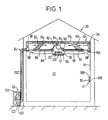
- Figure 1 is a cross sectional view of a house and an air conditioning system in accordance with a preferred embodiment of the present invention.
- Figure 2 is a partially cutaway perspective view of an indoor unit of the air conditioning system shown in Figure 1.
- Figure 3 is a perspective view of a radiation surface of the indoor unit shown in Figure 2.
- Figure 4 is a cross sectional view of the indoor unit shown in Figures 1 and 2.
- Figure 5 is a cross sectional view of the radiation plate shown in Figures 1 and 2.
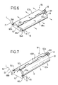
- FIGs 6 and 7 are perspective views of the louver mechanism shown in Figure 2.
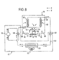
- FIG 8 is a block diagram of the air conditioning system shown in Figure 1.
- Figure 9 is a perspective view of the remote controller shown in Figure 1.
- Figure 10 is a block diagram of the remote controller shown in Figure 9.
- FIG 11 is a block diagram of the control subsystem of the air conditioning system shown in Figure 1.
- Figure 12 is a flow chart illustrating the cooling and heating operations of the air conditioning system shown in Figure 1.
- Figure 13 is a cross sectional view of the cooling and heating by convection of the house shown in Figure 1.
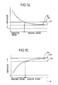
- Figure 14 illustrates the change in room temperature while cooling the house shown in Figure 1.
- Figure 15 illustrates the change in room temperature while heating the house shown in Figure 1.
- Figure 16 is a cross sectional view of a house and an air conditioning system in accordance with a second embodiment of the present invention.
- FIG 17 is a block diagram of the air conditioning system shown in Figure 16.
- Figure 18a is a flow chart illustrating the cooling operation of the air conditioning system shown in Figure 16.
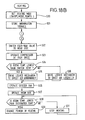
- Figure 18b is a flow chart illustrating the heating operation of the air conditioning system shown in Figure 16.
- Figure 19 is a block diagram of an air conditioning system in accordance with a third embodiment of the present invention.
- Figure 20 is a cross sectional view of a house and an air conditioning system in accordance with a fourth embodiment of the present invention.
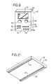
- Figure 21 is a perspective view of a radiation surface of the indoor unit shown in Figure 20.
- Figure 1 is a cross sectional view of a house and an air conditioning system in accordance with a preferred embodiment of the present invention.
- a conventional house 30 includes room 32 which serves as a residential area.
- Air conditioning apparatus 34 includes an indoor unit 36 installed on the ceiling 38 of room 32 and an outdoor unit 40 installed outside the house 30.
- a remote controller 42 is attached to a wall 44 of room 32.
- FIG. 2 is a partially cutaway perspective view of the indoor unit 36.
- Figure 3 is a perspective view of a radiation surface of the indoor unit 36.
- Figures 4 and 5 are cross sectional views of the indoor unit 36 and a radiation plate of indoor unit 36, respectively.
- Container 50 of the indoor unit 36 is shaped like a flat box which covers the entire surface of ceiling 38.
- the upper wall of container 50 is fixedly attached to ceiling 38 (see Figure 1).
- the lower wall of container 50 fixedly attached to ceiling 38 (see Figure 1).
- the lower wall of container 50 includes a projection portion 52 and plates 54 and 56.
- the long projection portion 52 is positioned in the near center portion of the lower wall of container 50 (see Figure 3).
- Plates 54 and 56 each have a material attached which resists the formation of dew or condensed water droplets, and which also has high water absorption and retention properties.
- plate 54 (or plate 56) includes plate-shaped foam urethane portion 58, plastic plates 60 and 62 that sandwich the plate-shaped foam urethane portion 58, and a group of hair-like projections 64 implanted onto the surface of plastic plate 60 and facing the room area.
- the combination of foam urethane portion 58 and plastic plates 60 and 62 possesses low heat conductivity. Consequently, dew or water condensation does not form easily, even with uneven cooling. In the event dew or water condensation occurs, the moisture is retained or absorbed by the group of implanted hair-like projections 64.
- the material used for each of the implanted hair-like projections 64 may be, for example, a fiber.
- the radiation surface 66 of plate 54 (and 56) is formed by implanting the complete surface of plastic plate 60 facing the room area with the group of hair-like projections 64.
- Plates 54 and 56 each include band-shaped inlet portions 68 disposed beside a respective wall 44 of room 32 and running parallel to projection portion 52.
- Band-shaped nozzles 70 and 72 are formed by the areas defined between respective plates 54 and 56 and projection portion 52, and running parallel to inlet portions 68.
- symmetrical air circulation routes 74 and 76 are defied within container 50 from inlet portions 68 toward nozzles 70 and 72.
- stratified heat insulating material 78 is fixedly attached to the complete inner surface of container 50, except for the inner surfaces of plates 54 and 56.
- Indoor heat exchangers 80 and 82 are arranged diagonally from the sides of, and running parallel to, inlet portions 68 in the path of circulation routes 74 and 76.
- a long, cross flow fan 84 is arranged in parallel with projection portion 52.
- One of the ends of cross flow fan 84 is rotatably supported by bearing 86 fixedly attached to a side wall of container 50.
- the other end of cross flow fan 84 is connected directly to the output axis of fan motor 88 (motor not shown) fixedly attached to the opposite side wall of container 50 (see Figure 2).
- Narrowing members 90 and 92 project toward the inlet side of cross flow fan 84 from the ends nearest to the projection portion 52 of plates 54 and 56 respectively.
- Cross flow fan 84 and narrowing members 90 and 92 form room fan 94 (i.e.,a ventilation fan). That is, room fan 94 pulls in air from inlet portions 68 of container 50 and directs the air to nozzles 70 and 72 according to the operation of fan motor 88.
- a louver mechanism 96 is arranged within the area defined by projection portion 52.
- Figures 6 and 7 show perspective views of the louver mechanism 96.
- the louver mechanism 96 include a grille 98 arranged above and running parallel to projection portion 52.
- Grille 98 includes a pair of belt-shaped grille wings 100a and 100b, which are connected pivotably to each other by axis member 102.
- Boss parts 104a and 104b are formed to extend from the sides of grille wings 100a and 100b, respectively.
- Boss parts 104 a and 104b are inserted slidably into slits 106a and 106b which are formed in an end wall of projection portion 52.
- the directions of slits 106a and 106b are horizontal and run parallel to a connecting line between the bottom of inlet portions 68.
- axis member 102 is projected beyond an end surface of grille wing 100a and 100b.
- Projecting portion 102a of axis member 102 is connected rotatably with an eccentric portion of the disc surface of disc cam 108.
- the center portion of disc cam 108 is connected rotatably with an output axis of a louver drive motor 110 which is supported inside the projection portion 52.
- grille wings 100a and 100b are positioned in the horizontal direction (see Figure 6) if projecting portion 102a of axis member 102 is driven to its lowermost position on cam 108 by louver drive motor 110. In this case, grille wings 100a and 100b are disposed parallel to the inner bottom surface of projection portion 52.
- the air circulating through indoor heat exchangers 80 and 82 is directed through nozzles 70 and 72, and along radiation surfaces 66 toward inlet portions 68 (that is, along the lateral direction).
- grille wings 100a and 100b are shaped like a reverse character V from a side view.
- the air circulating through indoor heat exchangers 80 and 82 is blown downward through nozzles 70 and 72 towards the center portion of room 32.
- Outdoor unit 40 includes outdoor heat exchanger 120, outdoor fan 122, compressor 124, four-way (reversible) valve 126, and expansion valve 128 (i.e., a pressure reducing apparatus) disposed in container 130.
- a four-way valve 126, a parallel circuit including indoor heat exchangers 80 and 82 of indoor unit 36, an expansion valve 128, and an outdoor heat exchanger 120 are connected in series with compressor 124, and refrigerant is passed through refrigerant communication tube 132.
- the above-disclosed structure provides a reversible-mode air conditioning system having a refrigerating and heating cycle.
- Remote controller 42 is disclosed below in detail with respect to Figures 1 and 9.
- Figure 9 is a perspective view of remote controller 42.
- a control box 134 which is disposed lnside indoor unit 36 and operated by remote controller 42, is described in more detail at a later point.
- Remote controller 42 includes container 140.
- a display 142 which may be for example a liquid crystal display, is fixedly attached to an upper portion of front panel 144 of container 140.
- Control knobs 146 and 148 are mounted side by side at the middle portion of front panel 144.
- Control knob 146 regulates the temperature setting at which the air conditioning system switches between radiation and convection operations.
- Knob 148 is used to input a predetermined temperature to the system. The operation of both knobs is disclosed in more detail below.
- Mounted on the lower portion of the front panel 144 is an on/off power switch 150, a cooling switch 152 and a heating switch 154 for selecting a cooling or heating mode of operation.
- ventilation slots 156 are formed on the lower portion of front panel 144 in container 140 so that the air in the room 32 comes into contact with temperature sensor 158 disposed in container 140.
- a transmitter 160 Attached to the upper portion of container 140 is a transmitter 160, which may be for example an infrared transmitter, and which transmits signals including control information to be received by control box 134 in indoor unit 36.
- Controller 162 is connected to liquid crystal display 142, temperature sensor 158, transmitter 160 and keys (i.e., knobs and switches) 164, which include inputs from temperature knobs 146 and 148 and switches 150, 152 and 154.
- the controller 162 which may include a known process controller or microcomputer, directs transmitter 160 to transmit the switching and temperature information from knobs 146 and 148, the cooling or heating selection from switches 152 and 154, and the power on/off selection from switch 150 (all provided from the group of keys 164), and the air temperature of room 32 as detected by temperature sensor 158. Except for the power on/off information, the above-described data is transmitted only when the power on/off switch is on.
- the liquid crystal display 142 selectively displays the above-described information with alphanumeric characters.
- the signal transmitted from transmitter 160 is received by receiver 166, which is attached to a lower surface of container 50 of indoor unit 36 (see Figure 1).
- the receiver 166 passes this signal to the control box 134 in indoor unit 36.
- Control box 134 controls the operations of indoor unit 36 and outdoor unit 40 in response to the data included in the received signal.
- control box 134 includes CPU (central processing unit) 168 and memory 170.
- Memory 170 may include a random access memory (RAM) area.
- CPU 168 includes a comparison circuit 172, a processing circuit 174 and a signal identifier 176.
- Memory 170 stores the information about room temperature, the temperature settings of knobs 146 and 148, and so on.
- CPU 168 is connected to indoor unit 36 and outdoor unit 40. That is, CPU 168 is connected to an electric drive motor (not shown) of compressor 124 through inverter circuit 178, to four-way valve 126 through switching circuit 180, to louver drive motor 110 through louver drive circuit 182, to room fan 94 through drive circuit 184, and to outdoor fan 122 through drive circuit 186.
- an electric drive motor (not shown) of compressor 124 through inverter circuit 178
- inverter circuit 178 to four-way valve 126 through switching circuit 180
- louver drive motor 110 through louver drive circuit 182
- room fan 94 through drive circuit 184
- outdoor fan 122 through drive circuit 186.
- CPU 168 controls each component described above in response to the information signal received from transmitter 160 in remote controller 42. Thus, CPU 168 controls the air conditioning system's cycling by switching between the cooling and heating modes in response to the selection signal from transmitter 160. Additionally, CPU 168 controls the operation of compressor 124 in both the heating and cooling modes, by initially operating compressor 124 at a high speed and subsequently operating it at a variable speed by changing the frequency of the input, in response to the difference between the designated (set) temperature selected by knob 148 and the room temperature detected by temperature sensor 158. Compressor 124 is stopped if the temperature detected by temperature sensor 158 equals the designated temperature.
- CPU 168 controls switching of the air conditioning system between the radiation and convection modes of operation, in response to the switching temperature input from knob 146. That is, during a heating cycle of operation, convection heating is selected if the temperature detected by sensor 158 is lower than the switching temperature determined by knob 146. Radiation heating is selected if the temperature detected by sensor 158 is higher than the switching temperature determined by knob 146. Conversely, during a cooling cycle of operation, convection (or radiation) cooling is selected if the temperature detected by the sensor 158 is higher (or lower) than the switching temperature.
- CPU 168 also controls the rotation of louver drive motor 110 so that grille wings 100a and 100b are positioned either in the shape of an inverted V or laterally (horizontally) for convection or radiation air conditioning, respectively.
- either cooled or heated air may be directed toward the center area of room 32 if the air conditioning load is large or the cooling or heating operation has just started.
- FIG 12 is a flow chart that illustrates the cooling and heating operation of the air conditioning system disclosed with respect to Figures 1-11.
- an operator (not shown) first sets on/off switch 150 to the ON position.
- cooling switch 152 is pushed to activate the cooling mode of operation.
- Knob 146 is set to a desired switching temperature, and knob 148 is set to its designated temperature (step S1).
- the above-described cooling mode command signal and the temperature settings from knobs 146 and 148 are transmitted from transmitter 160 to receiver 166, where these signals are then coupled to CPU 168. Under the control of CPU 168, these command and data signals are stored in memory 170 (step S2).
- CPU 168 determines whether the command for cooling is present or not (step S3). In this case, the command signal for the cooling mode is present. Consequently, four-way valve 126 is switched to the cooling cycle position (step S4). As discussed earlier, the electric drive motor of compressor 124 is operated at high speed for the initial startup to provide maximum cooling (step S5). Thus, referring also to Figure 8, during the cooling mode of operation, the refrigerant is compressed in compressor 124 and circulated through the system from compressor 124 to four-way valve 126, outdoor heat exchanger 120, expansion valve 128 and then to indoor heat exchangers 80 and 82 in the direction designated by the dashed arrows (A).
- the room air temperature detected by temperature sensor 158 in remote controller 42 is transmitted by transmitter 160 to receiver 166 and coupled to CPU 168.
- CPU 168 compares the received room temperature with the received switching temperature selected by knob 146 (step S6).
- the temperature sensed in room 32 is relatively high and, consequently, the air conditioning load is large.
- the room temperature is higher than the selected switching temperature. Consequently, CPU 168 provides a command signal to louver drive circuit 182 that causes louver drive motor 110 to position grille wings 100a and 100b in an inverted V (see Figure 7), in order to direct the air from nozzles 70 and 72 downward into the room area (step S7).
- CPU 168 then provides commands to drive circuits 184 and 186 to operate outdoor fan 122 and room fan 94 (steps S8 and S9).
- the air in room 32 is pulled in through inlet portions 68 and directed to air circulation paths 74 and 76.
- the air moving through air circulation paths 74 and 76 is heat-exchanged and cooled by indoor heat exchangers 80 and 82.
- the cooled air moving through indoor heat exchangers 80 and 82 are blown diagonally-downward into the room area from nozzles 70 and 72 (e.g., see Figure 13). In this manner, the residential areas are directly cooled by the use of convection cooling. Consequently, the residential area is cooled rapidly at the onset of the cooling cycle.
- step S10 the sensed room temperature is compared by CPU 168 with the designated temperature set by knob 148 (step S10). If the sensed room temperature is higher than the designated temperature (i.e., if the answer to step S10 is yes), then the cooling mode of operation is continued. However, the amount of cooling (i.e., the cooling output of compressor 124) may be continuously varied in response to the difference between the sensed room temperature and the designated temperature, by changing the operating speed of compressor 124 (step S11). More precisely, the frequency of the electrical input to the compressor 124 may be changed so that the cooling output of compressor 124 is proportional to the magnitude of the difference between the sensed room temperature and the designated temperature.
- CPU 168 again performs the operation of step S6.
- step S6 if the room temperature is determined by CPU 168 to be equal to or less than the switching temperature (i.e., the answer to step S6 is no), then step S12 is performed next.
- CPU 168 provides a command signal for louver drive circuit 182 to drive louver drive motor 110 and position grille wings 100a and 100b laterally or flat (see Figure 6), in order to direct the cooled air from nozzles 70 and 72 (step S12).
- the cool air streams from nozzles 70 and 72 are directed laterally along radiation surface 66 to inlet portions 68 (see Figure 1). These laterally directed streams of cool air from nozzles 70 and 72 are heat-exchanged with the air contacting radiation surface 66, so that the cooled streams of air act to cool radiation surface 66. Consequently, dew or water condensation does not form on radiation surface 66 because radiation surface 66 is cooled indirectly by the moving streams of cooled air instead of being cooled or heat-exchanged directly by circulating the refrigerant next to the radiation surface. Specifically, the temperature of radiation surface 66 is higher than that of the moving streams of cooled air, because radiation surface 66 is cooled by the moving streams of cooled air.
- dew or water condensation does not form on radiation surface 66 because the dew point temperature is lower than the temperature of the surrounding cool air. For example, if the temperature of the cooled column of air is 15°C, the temperature at radiation surface 66 will be higher than 15°C because a heat exchange has occurred between the air stream and the radiation surface. In the case, the relative humidity of the cooled air in contact with radiation surface 66 is generally about 85%, and the dew point temperature is about 12.5°C. Thus, dew or water condensation will not occur. Additionally, the heat conduction ratios for plates 54 and 56 are designed to be low, in order to prevent the formation of dew or water condensation.
- step S12 After performing step S12, steps S7 and S8 are performed as described earlier. Next, steps S9 and S10 are again performed. However, at this point for step S10, if the sensed room temperature is equal to or less than the designated temperature (i.e., the answer to step S10 is no), the next step performed is step S13. For step S13, CPU 168 provides a command signal to stop the operation of compressor 124. Then, step S10 is performed again.
- the air conditioning load responsive to the temperature in room 32 were to increase rapidly by, for example, opening windows in room 32 or the entrance of additional people into the cooled area, the expected increase in room temperature may be prevented by changing the cooling mode from radiation cooling to convection cooling (i.e., by performing steps S6 and S7). Also, an operator need only set knob 148 to a lower temperature if additional cooling is needed or desired (steps S6 and S7 would respond to this new setting).
- step S22 In the heating mode of operation, the answer to step S3 is no. Consequently, the next steps to be performed are steps S22 and S23.
- step S22 CPU 168 provides a command signal to switch four-way valve 126 to the heating position.
- the electric drive motor (not shown) for compressor 124 At the onset of heating, the electric drive motor (not shown) for compressor 124 is operated at high speed (step S23).
- the refrigerant is compressed in compressor 124 and circulated from compressor 124 to four-way valve 126, indoor heat exchangers 80 and 82, expansion valve 128, and outdoor heat exchanger 120 in the direction shown by the solid arrows (B).
- step S24 the next step to be performed is step S25.
- CPU 168 In performing the operation of step S25, CPU 168 provides an output command to louver drive circuit 182, which causes grille wings 100a and 100b of louver mechanism 96 to be positioned diagonally-downward (as shown in Figure 7) by louver drive motor 110. Thus, the heated streams of air from nozzles 70 and 72 are directed downward into the center of room area 32. Then CPU 168 issues command signals that are coupled to drive circuits 184 and 186 that, in turn, cause the operation of outdoor fan 122 and room fan 94 (steps S26 and S27).
- the air in room 32 is pulled in through from inlet portions 68 and circulated through air circulation routes 74 and 76.
- the streams of air that are circulated through air circulation routes 74 and 76 are heated by indoor heat exchangers 80 and 82.
- the heated columns of air flowing through indoor heat exchangers 80 and 82 are directed diagonally-downward from nozzles 70 and 72 into the center of the room. This operation provides convection heating. Consequently, at the onset of the heating mode of operation, the residential area is heated rapidly by convection heating (e.g., see Figure 13).
- step S28 The next step to be performed is step S28.
- CPU 168 compares the current, sensed room temperature with the designated temperature set by knob 148 on remote controller 42. If the sensed room temperature is lower than the designated temperature (i.e., the answer to step S28 is yes), then the heating mode of operation is continued.
- the amount of heat produced by the system i.e., heat power output
- the frequency of the electrical input to compressor 124 may be varied.
- step S24 The next operation to be performed is step S24 in Figure 12.
- the temperature TRH in room area 32 increases as shown in Figure 15.
- the room temperature TRH is increased to at least the value of the switching temperature TSH, the air conditioning load for the room is considered small.
- the next step to be performed is step S30.
- CPU 168 In performing the operation of step S30, CPU 168 provides a command signal to louver drive circuit 182 to drive louver drive motor 110 so as to position grille wings 100a and 100b of louver mechanism 96 in the lateral direction (flat as shown in Figure 6). Consequently, the heated streams of air from nozzles 70 and 72 are directed laterally along radiation surface 66 to inlet portions 68 (see Figure 1). Radiation surface 66 is heated by the warm air from nozzles 70 and 72. Thus, the residential area is heated by radiation heating in accordance with the present invention, and the residents are not subjected to uncomfortable drafts of air.
- step S30 the next steps to be performed in sequence are steps S25 through S28.
- the operations in these steps are similar to those described above with respect to the cooling mode of operation.
- step S28 if CPU 168 determines that the sensed room temperature TRH is equal to or greater than the designated temperature TDH (i.e., the answer to step S28 is no), then the next step to be performed is step S31. In this event, heating is discontinued by stopping the compressor drive motor. After step S31 is performed, CPU 168 then reperforms step S28, and so on.
- the air conditioning load for heating the room 32 is increased rapidly by, for example, opening windows to the heated area, the possibility of a significant decrease in room temperature may be eliminated by changing from the radiation heating mode to the convection heating mode of operation (by performing steps S24 and S25). A similar effect may be achieved so as to rapidly heat the room, by adjusting knob 148 to a higher temperature.
- FIG 16 is a cross sectional view of a second embodiment of the present invention.
- This second embodiment comprises the structure disclosed above in accordance with the first embodiment, and an additional structure of a dehumidifying apparatus.
- like numerals refer to like elements and, in the interest of convenience, the detailed descriptions of the like elements are not repeated.
- a second set of heat exchangers 190 and 192 for auxiliary reheating are fixedly attached to container 50 and supported within circulation routes 74 and 76 between respective indoor heat exchangers 80 and 82, and room fan 94.
- Auxiliary heat exchangers 190 and 192 are activated during heating when the room humidity is exceptionally high.
- Figure 17 is a block diagram of the air conditioning system shown in Figure 16
- Figure 18 is a flow chart that illustrates the cooling and heating modes of operation of the air conditioning system shown in Figure 17.
- auxiliary heat exchangers 190 and 192 are added to the elements disclosed in Figure 2, and heat exchangers 190 and 192 are connected in series with expansion valve 128 and one side of their respective indoor heat exchangers 80 and 82.
- refrigerant flow circuits 194 and 196 each include an on-off valve 198 connected in parallel with acapillary tube 200, which circuits are connected between indoor heat exchangers 80 and 82 and auxiliary heat exchangers (for heating) 190 and 192, respectively.
- on-off valve 202 is connected in parallel with expansion valve 128.
- FIG. 12 is a flow chart that represents the operation of the above-disclosed first embodiment of the present invention.
- the determination of whether or not the sensed room temperature has reached the dew point temperature is made in step S40. If the answer to step S40 is no, then on-off valves 198 and 202 are opened and closed, respectively (step 41). On the other hand, if the answer to step S40 is yes (i.e., dew or water condensation may easily form), then on-off valves 198 and 202 are closed and opened, respectively (step 42).
- auxiliary heat exchangers 190 and 192 are operated as heaters. Thus, the air streams cooled by indoor heat exchangers 80 and 82 are heated by auxiliary heat exchangers 190 and 192. Consequently, the dew point temperature is decreased and dew or water condensation is not likely to form.
- step S40 the next step to be performed is step S40. Thereafter, the loop comprising steps S42 and S40 is continued until the answer to step S40 is determined to be no. In that case, the operation continues with step S41.
- auxiliary heat exchangers 190 and 192 may be adapted to operate as dehumidifiers.
- a consonant structure for controlling the rotation of the room fan 94 must also be adopted. That is, the quantity of air flowing through indoor heat exchangers 80 and 82 should be decreased so that the latent heat exchange is increased by a proportional amount. This operation serves to drop the dew point temperature.
- FIG 19 is a block diagram of an air conditioning system in accordance with the third embodiment of the present invention.
- the third embodiment utilizes electrically-controlled expansion valve 210 whose quantity of reduction is varied widely by a driving member such as an electric drive motor, instead of utilizing expansion valve 128 and on-off valve 202 as disclosed above with respect to the second embodiment shown in Figure 17.
- Figure 20 is a cross sectional view of an air conditioning system in accordance with the fourth embodiment of the present invention.
- the cooled or heated air flowing from heat exchanger 80 in the indoor unit is directed only from one end of the lower surface of the indoor unit to cool or heat radiating surface 66, instead of directing the cooled or heated air from the center portion of the lower surface of the indoor unit. That is, the air conditioning system in the fourth embodiment has a larger radiation surface 66 than that disclosed with respect to the first to third embodiments.
- Figure 21 shows a perspective view of the radiation surface 66 of indoor unit 36.
- the cooled or heated stream of air is directed from a nozzle 212 located at one end of the lower surface of indoor unit 36, and along radiation surface 66.
- Louver mechanism 216 is structured to operate similarly to louver mechanism 96 as positioned in inlet portion 214 and disclosed above with respect to Figure 1. Additionally, auxiliary heat exchanger 190 as disclosed above with respect to the second embodiment may be also adapted as shown in Figure 21 to operate as an active dehumidifier (i.e., to lower room humidity in addition to lowering the dew point temperature).
- the air conditioning system in accordance with the present invention is not intended to be so limited and also may be attached to a wall of the room.
Landscapes
- Engineering & Computer Science (AREA)
- Chemical & Material Sciences (AREA)
- Combustion & Propulsion (AREA)
- Mechanical Engineering (AREA)
- General Engineering & Computer Science (AREA)
- Life Sciences & Earth Sciences (AREA)
- Sustainable Development (AREA)
- Air Conditioning Control Device (AREA)
- Air-Conditioning Room Units, And Self-Contained Units In General (AREA)
Applications Claiming Priority (2)
| Application Number | Priority Date | Filing Date | Title |
|---|---|---|---|
| JP02076615A JP3128127B2 (ja) | 1990-03-28 | 1990-03-28 | 空気調和装置 |
| JP76615/90 | 1990-03-28 |
Publications (2)
| Publication Number | Publication Date |
|---|---|
| EP0449628A2 true EP0449628A2 (fr) | 1991-10-02 |
| EP0449628A3 EP0449628A3 (en) | 1992-09-02 |
Family
ID=13610255
Family Applications (1)
| Application Number | Title | Priority Date | Filing Date |
|---|---|---|---|
| EP19910302738 Withdrawn EP0449628A3 (en) | 1990-03-28 | 1991-03-28 | Air conditioning system |
Country Status (3)
| Country | Link |
|---|---|
| US (1) | US5228500A (fr) |
| EP (1) | EP0449628A3 (fr) |
| JP (1) | JP3128127B2 (fr) |
Cited By (7)
| Publication number | Priority date | Publication date | Assignee | Title |
|---|---|---|---|---|
| DE10128381C1 (de) * | 2001-06-06 | 2003-01-09 | Ltg Ag | Einrichtung und Verfahren zum Heizen und/oder Kühlen eines Raumes |
| GB2378502A (en) * | 2001-06-06 | 2003-02-12 | Ltg Ag | Apparatus for heating or cooling a room |
| US7481627B2 (en) | 2004-08-30 | 2009-01-27 | Mat Industries Llc | Air compressor tools that communicate with an air compressor |
| US7789102B2 (en) | 2004-08-30 | 2010-09-07 | Mat Industries Llc | Air compressor having a pneumatic controller for controlling output air pressure |
| WO2011110975A1 (fr) * | 2010-03-09 | 2011-09-15 | Koninklijke Philips Electronics N.V. | Appareil de régulation de la température et procédé de thermorégulation d'un corps humain |
| CN114440310A (zh) * | 2022-02-24 | 2022-05-06 | 海信(山东)空调有限公司 | 空调器和空调器出风的控制方法 |
| CN115388486A (zh) * | 2022-08-03 | 2022-11-25 | 哈尔滨工业大学(深圳) | 基于自然通风建筑的混合冷却系统 |
Families Citing this family (13)
| Publication number | Priority date | Publication date | Assignee | Title |
|---|---|---|---|---|
| US5632327A (en) * | 1992-03-20 | 1997-05-27 | Energy Ceiling Company Limited | Temperature control |
| KR100539764B1 (ko) * | 2004-05-21 | 2006-01-12 | 엘지전자 주식회사 | 유니터리 공기조화기 및 그의 제어방법 |
| JP4999944B2 (ja) * | 2009-12-17 | 2012-08-15 | 木村工機株式会社 | 誘引放射空調機 |
| JP5466738B2 (ja) * | 2012-08-22 | 2014-04-09 | 株式会社インターセントラル | ヒートポンプエアコンを利用した蓄熱型放射冷暖房システム |
| JP2015055434A (ja) * | 2013-09-13 | 2015-03-23 | 株式会社 テスク資材販売 | 空調システム |
| CN106051911B (zh) * | 2015-04-02 | 2020-10-16 | 松下知识产权经营株式会社 | 风扇装置和天花板吊挂式空调设备 |
| CN105757858B (zh) * | 2016-04-11 | 2018-10-26 | 余志锋 | 防结露型空调辐射板及其工作方法 |
| US10883753B2 (en) | 2016-04-29 | 2021-01-05 | King Fahd University Of Petroleum And Minerals | Radiant cooling apparatus and system |
| CN106061202B (zh) * | 2016-06-27 | 2018-05-01 | 周丐社 | 螺旋降温机房 |
| CN108266868B (zh) * | 2018-01-11 | 2019-12-10 | 广东美的制冷设备有限公司 | 空调器的控制方法和空调器 |
| TWI678504B (zh) * | 2018-10-12 | 2019-12-01 | 群光電能科技股份有限公司 | 儲冰量調整系統與儲冰量調整方法 |
| FR3129959B1 (fr) * | 2021-12-03 | 2024-06-21 | Damien Lang | Plafond diffusant hybride reversible pour elements rayonnants |
| US20250271150A1 (en) * | 2024-02-26 | 2025-08-28 | Warmboard, Inc. | Air conditioning system |
Family Cites Families (16)
| Publication number | Priority date | Publication date | Assignee | Title |
|---|---|---|---|---|
| US2245470A (en) * | 1937-05-03 | 1941-06-10 | Fuchs Gunter | Ceiling heating system |
| US2392240A (en) * | 1943-10-06 | 1946-01-01 | Frankel Enrique | System for heating, cooling, and air conditioning of buildings |
| US2533407A (en) * | 1945-12-04 | 1950-12-12 | Punch Engineering Pty Ltd | Heating and cooling system |
| US3097650A (en) * | 1958-06-12 | 1963-07-16 | Reflectotherm Inc | Therapeutic radiant cooling system |
| US2966780A (en) * | 1958-10-01 | 1961-01-03 | Reflectotherm Inc | Radiant cooling systems |
| US3225788A (en) * | 1959-06-30 | 1965-12-28 | Carrier Corp | Air distributing units |
| DE1279916C2 (de) * | 1963-07-23 | 1973-01-25 | Otto Heinz Brandi Dipl Ing | Verfahren und Vorrichtung zur Beheizung, Kuehlung, Be- und Entlueftung von Innenraeumen mit Zuluft |
| US3453413A (en) * | 1965-12-10 | 1969-07-01 | Aztec Ind Inc | Rough surface radiant heater |
| US3905203A (en) * | 1973-06-15 | 1975-09-16 | Carlyle W Jacob | Refrigeration and water condensate removal apparatus |
| DE2333158A1 (de) * | 1973-06-29 | 1975-01-16 | Bosch Siemens Hausgeraete | Kuehlgeraet, insbesondere konvektiv durch luftumwaelzung gekuehlter no-frostkuehlschrank |
| US4005698A (en) * | 1974-10-18 | 1977-02-01 | International Business Machines Corporation | Photon energy converter |
| US4026271A (en) * | 1976-05-19 | 1977-05-31 | Ametek, Inc. | Solar collector coating |
| US4198222A (en) * | 1977-12-01 | 1980-04-15 | General Electric Company | Condensation preventing arrangement for interior of a household refrigerator |
| JPS5812934A (ja) * | 1981-07-16 | 1983-01-25 | Mitsubishi Electric Corp | 空調機 |
| SE459447B (sv) * | 1987-06-17 | 1989-07-03 | Stefan Jacek Moszkowski | Saett och anordning foer att ventilera ett rum genom inblaasning av luft horisontellt under en vaermevaexlande takmonterad panel |
| JPH0813515B2 (ja) * | 1987-07-09 | 1996-02-14 | 株式会社ブリヂストン | 帯状部材の端部挟持装置 |
-
1990
- 1990-03-28 JP JP02076615A patent/JP3128127B2/ja not_active Expired - Fee Related
-
1991
- 1991-03-19 US US07/672,016 patent/US5228500A/en not_active Expired - Fee Related
- 1991-03-28 EP EP19910302738 patent/EP0449628A3/en not_active Withdrawn
Cited By (9)
| Publication number | Priority date | Publication date | Assignee | Title |
|---|---|---|---|---|
| DE10128381C1 (de) * | 2001-06-06 | 2003-01-09 | Ltg Ag | Einrichtung und Verfahren zum Heizen und/oder Kühlen eines Raumes |
| GB2378502A (en) * | 2001-06-06 | 2003-02-12 | Ltg Ag | Apparatus for heating or cooling a room |
| GB2378502B (en) * | 2001-06-06 | 2006-01-04 | Ltg Ag | Apparatus for,and method of heating or cooling a room |
| US7481627B2 (en) | 2004-08-30 | 2009-01-27 | Mat Industries Llc | Air compressor tools that communicate with an air compressor |
| US7789102B2 (en) | 2004-08-30 | 2010-09-07 | Mat Industries Llc | Air compressor having a pneumatic controller for controlling output air pressure |
| WO2011110975A1 (fr) * | 2010-03-09 | 2011-09-15 | Koninklijke Philips Electronics N.V. | Appareil de régulation de la température et procédé de thermorégulation d'un corps humain |
| CN114440310A (zh) * | 2022-02-24 | 2022-05-06 | 海信(山东)空调有限公司 | 空调器和空调器出风的控制方法 |
| CN114440310B (zh) * | 2022-02-24 | 2023-07-25 | 海信空调有限公司 | 空调器和空调器出风的控制方法 |
| CN115388486A (zh) * | 2022-08-03 | 2022-11-25 | 哈尔滨工业大学(深圳) | 基于自然通风建筑的混合冷却系统 |
Also Published As
| Publication number | Publication date |
|---|---|
| JP3128127B2 (ja) | 2001-01-29 |
| JPH03279728A (ja) | 1991-12-10 |
| US5228500A (en) | 1993-07-20 |
| EP0449628A3 (en) | 1992-09-02 |
Similar Documents
| Publication | Publication Date | Title |
|---|---|---|
| US5228500A (en) | Air conditioning system | |
| US6253559B1 (en) | Heating and cooling unit | |
| US5267450A (en) | Air conditioning apparatus | |
| JP2003074962A (ja) | 空気調和装置 | |
| JPH04143541A (ja) | 空気調和装置 | |
| US5934084A (en) | Air conditioner having a method and apparatus for performing a dry operation to remove humidity during a cooling mode | |
| JP2004116977A (ja) | 空気調和機 | |
| KR100504588B1 (ko) | 공기조화기 | |
| JP3801268B2 (ja) | 空気調和機 | |
| JP2005009849A (ja) | 空気調和機 | |
| JPH05280762A (ja) | 輻射パネル付室内ユニット | |
| JP3523423B2 (ja) | 空気調和機 | |
| CN110274388B (zh) | 一种暖风机及其控制方法 | |
| JP3526367B2 (ja) | 空気調和機 | |
| KR100354065B1 (ko) | 냉난방 겸용 멀티 공기조화기의 운전제어방법 | |
| JP3170556B2 (ja) | 空気調和機 | |
| JP3488763B2 (ja) | 空気調和機 | |
| JP2610271B2 (ja) | 空気調和機 | |
| JP2011075168A (ja) | 空気調和機 | |
| CN208059064U (zh) | 一种智能空调散热器 | |
| JPH10160202A (ja) | 輻射式空気調和装置 | |
| US11525584B2 (en) | Method of modifying air conditioner for heating | |
| JP7437559B1 (ja) | 潜顕分離換気空調システム | |
| JP7648889B2 (ja) | 空気調和装置の室内機 | |
| JP2960418B2 (ja) | 空気調和機 |
Legal Events
| Date | Code | Title | Description |
|---|---|---|---|
| PUAI | Public reference made under article 153(3) epc to a published international application that has entered the european phase |
Free format text: ORIGINAL CODE: 0009012 |
|
| 17P | Request for examination filed |
Effective date: 19910419 |
|
| AK | Designated contracting states |
Kind code of ref document: A2 Designated state(s): DE FR GB |
|
| PUAL | Search report despatched |
Free format text: ORIGINAL CODE: 0009013 |
|
| AK | Designated contracting states |
Kind code of ref document: A3 Designated state(s): DE FR GB |
|
| 17Q | First examination report despatched |
Effective date: 19931018 |
|
| STAA | Information on the status of an ep patent application or granted ep patent |
Free format text: STATUS: THE APPLICATION IS DEEMED TO BE WITHDRAWN |
|
| 18D | Application deemed to be withdrawn |
Effective date: 19940301 |