EP0449013A2 - Dispositif de lecture d'images utilisant des capteurs linéaires à couplage de charge - Google Patents
Dispositif de lecture d'images utilisant des capteurs linéaires à couplage de charge Download PDFInfo
- Publication number
- EP0449013A2 EP0449013A2 EP91103613A EP91103613A EP0449013A2 EP 0449013 A2 EP0449013 A2 EP 0449013A2 EP 91103613 A EP91103613 A EP 91103613A EP 91103613 A EP91103613 A EP 91103613A EP 0449013 A2 EP0449013 A2 EP 0449013A2
- Authority
- EP
- European Patent Office
- Prior art keywords
- color
- difference signals
- color difference
- signals
- regions
- Prior art date
- Legal status (The legal status is an assumption and is not a legal conclusion. Google has not performed a legal analysis and makes no representation as to the accuracy of the status listed.)
- Granted
Links
Images


Classifications
-
- H—ELECTRICITY
- H04—ELECTRIC COMMUNICATION TECHNIQUE
- H04N—PICTORIAL COMMUNICATION, e.g. TELEVISION
- H04N1/00—Scanning, transmission or reproduction of documents or the like, e.g. facsimile transmission; Details thereof
- H04N1/46—Colour picture communication systems
- H04N1/56—Processing of colour picture signals
- H04N1/58—Edge or detail enhancement; Noise or error suppression, e.g. colour misregistration correction
-
- H—ELECTRICITY
- H04—ELECTRIC COMMUNICATION TECHNIQUE
- H04N—PICTORIAL COMMUNICATION, e.g. TELEVISION
- H04N1/00—Scanning, transmission or reproduction of documents or the like, e.g. facsimile transmission; Details thereof
- H04N1/46—Colour picture communication systems
- H04N1/56—Processing of colour picture signals
- H04N1/60—Colour correction or control
- H04N1/6016—Conversion to subtractive colour signals
- H04N1/6022—Generating a fourth subtractive colour signal, e.g. under colour removal, black masking
- H04N1/6025—Generating a fourth subtractive colour signal, e.g. under colour removal, black masking using look-up tables
Definitions
- the present invention relates to an image reader using CCD line sensors, such as a prepress flat-bed color scanner, and more particularly to the technique of reducing noise components included in image signals output from the CCD line sensors.
- Output voltage of a CCD line sensor is not 0V even when there is no incident light (i.e. in a light-shielded state).
- black reference level an output voltage in the light-shielded state for use as a reference (hereinafter referred to as black reference level) and to subtract this black reference level from an output voltage occurring during a light reception to obtain an output voltage proportional to a quantity of incident light.
- a CCD line sensor normally includes, at ends of its pixel array, a plurality of pixels which are constantly in a light-shielded condition (hereinafter referred to as black reference pixels). Conventionally, compensation for the output of the CCD line sensor is carried out using the black reference pixels as set out below.
- the output signal of one particular black reference pixel or an average of output signals of a plurality of black reference pixels in the CCD line sensor is sampled and held as the black reference level for one line.
- the black reference level is subtracted from output signals (image signals) of effective pixels, thereby to compensate for the output of the CCD line sensor.
- the output compensation is effected by subtracting the same black reference level from all image signals covering one line read by the CCD line sensor. If noise is included in the black reference level, all the image signals for one line are prone to its influence. The image recorded by means of these signals will reflect the noise in the form of a streak often striking to sight.
- the noises included in the individual black reference pixels are leveled out. This, of course, results in a reduction in the influence of noise compared with the method of using the output signal of one black reference pixel as the black reference level.
- an image scanner such as a prepress color scanner carries out logarithmic transformation of image signals to obtain density signals. Since the scale of shadow portions is enlarged through this operation, the noise still is visible in the form of a streak in the shadow portions.
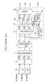
- Fig. 1 is a block diagram showing an outline of a conventional image reader using CCD line sensors.
- Fig. 2 schematically shows levels of B, G and R components in various parts of the image reader and noise levels superposed on the respective components.
- references 1B, 1G and 1R denote CCD line sensors for detecting blue (B), green (G) and red (red) color components of light transmitted from a color original.
- Output signals from the CCD line sensors 1B, 1G and 1R are converted by an analog-to-digital converter 2 into digital image signals DB, DC and DR, respectively, which undergo an output compensation process at an output compensator 3 using a black reference level as described hereinbefore.
- the image signals after the output compensation undergo a logarithmic transformation at a logarithmic transformer 4, and are then applied to a color change circuit 5.
- Fig. 2 (a) shows the image signals B, G and R as applied to the color change circuit 5. As illustrated, noises ⁇ NB, ⁇ NG and ⁇ NR are superimposed on the respective image signals.
- the color change circuit 5 functions to change these log-transformed color image signals B, G and R into four color components of yellow (Y), magenta (M), cyan (C) and black (K).
- the image signals B, G and R output from the logarithmic transformer 4 are applied to a color difference signal extractor 51 and a luminance signal detector 52.
- the luminance signal detector 52 detects, as a luminance signal Max, the signal having the highest signal level among the image signals B, G and R input thereto. It is assumed here that the image signal B is detected as the luminance signal Max (see Fig. 2 (b)).
- the color difference signal extractor 51 extracts color difference signals CB, CG and CR by subtracting the input image signals B, G and R from the luminance signal Max, respectively. As a result of this extraction process, as shown in Fig. 2 (c), noises ⁇ NB and ⁇ NG are superimposed on the color difference signal CG, and noises ⁇ NB and ⁇ NR on the color difference signal CR.
- the color difference signal CB is in zero level at this stage.
- the color difference signals CB, CG and CR are applied to a basic color corrector 53 for correcting turbidity of color inks and variations in spectral characteristics of the optical system.
- the color corrector 53 includes three lookup tables corresponding to the color difference signals CB, CG and CR. Each lookup table is formed of a memory which receives the corresponding color difference signal as an address, and outputs data stored in a corresponding address region as a color-corrected image signal.
- Fig. 3 shows a typical example of color correction characteristics of the color corrector 53.
- Such color correction characteristics are set to the individual lookup tables.
- references KB, KG and KR are coefficients for multiplying the input color difference signals CB, CG and CR to effect color correction, i.e. enlargement ratios of the color difference signals, respectively.
- these coefficients correspond to the gradient of the color correction characteristics.
- an ordinary image reader has such color correction characteristics that, in order to provide a good color reproduction in highlight portions, the gradient is made steep in a region of small color difference signals to enlarge the small color difference signals.
- the noises input to the color corrector 53 as superimposed on the color difference signals are enlarged in the region of small color difference signals.
- Fig. 2 (d) shows color difference signals CY(KB ⁇ CB), CM(KG ⁇ CG) and CC(KR ⁇ CR) corrected by the color corrector 53.
- noise components expressed by ( ⁇ NB ⁇ NG)KG are superimposed on the color difference signal CM
- noise components expressed by ( ⁇ NB ⁇ NR)KR are applied to an adder 55 in the next stage.
- the luminance signal Max output from the luminance signal detector 52 is applied to a subtracter 54 as well as the color difference signal extractor 51 noted above.
- the subtracter 54 forms a black signal K by subtracting the luminance signal Max from a white reference signal W shown in Fig. 2 (e).
- a noise ⁇ NB is superimposed on the black signal K.
- This black signal K is applied to the adder 55.
- the adder 55 outputs image signals Y, M and C resulting from color changes effected by adding the black signal K to the corrected color difference signals CY, CM and CC, respectively.
- a noises expressed by ⁇ NB is superimposed on the image signal Y, noises ⁇ NB(KG-1) ⁇ NG ⁇ KG on the image signal M, and noises ⁇ (KR-1) ⁇ N ⁇ KR on the image signal C.
- the noise ( ⁇ NB ⁇ NG)KG superimposed on the image signal M results from the noise ⁇ NB ⁇ NG superimposed on the color difference signal CG and multiplied by KG at the color corrector 53.
- the noises ( ⁇ NB ⁇ NR)KR superimposed on the image signal C result from the noises ⁇ NB ⁇ NR superimposed on the color difference signal CR and multiplied by KR at the color corrector 53.
- the noises included in the color difference signals are enlarged where the color difference signals are small. Moreover, maximum values of B, G and R are reduced in a shadow portion, with the color difference signals tending to be small. As a consequence, the noises become emphasized in the shadow portion.
- the present invention is based on the findings described above, and its principal object is to provide an image reading apparatus using CCD line sensors, which is capable of reducing noises in image signals readily generated in shadow portions and in regions where color difference signals are small.
- an image reading apparatus using CCD line sensors comprising a logarithmic transformer for effecting logarithmic transformation of blue (B), green (G) and red (R) signals resulting from reading of a color original by the CCD line sensors; a luminance signal detector for detecting a luminance signal among signals emerging from the logarithmic transformation; a color difference signal extractor for extracting color difference signals by subtracting the luminance signal from the respective signals emerging from the logarithmic transformation; a color corrector for effecting color correction of the color difference signals, the color corrector including a plurality of color correcting devices having color correction characteristics with different enlargement ratios of the color difference signals at least for regions where the color difference signals are small; a control device for manually switching the color correcting devices; and an adder for obtaining yellow (Y), magenta (M) and cyan (C) image signals by adding a black signal obtained from the luminance signal to the color difference signals color-corrected by the color corrector.
- a logarithmic transformer for effecting logarith
- the number of color correcting devices included in the color corrector is not limitative.
- Two color correcting devices may be provided, for example, which are a first color correcting device having color correction characteristics for enlarging the color difference signals in the regions where the color difference signals are small, and a second color correcting device having color correction characteristics for limiting the enlargement ratios of the color difference signals in the regions where the color difference signals are small.
- the control device is then operable to select the first color correcting device or the second color correcting device.
- the first and second color correcting devices are formed of a first and a second groups of lookup tables, respectively, for receiving the color difference signals as addresses and outputting data stored in corresponding address regions as color-corrected image signals.
- each of the first and second groups of lookup tables includes three lookup tables corresponding to the three color difference signals.
- the second group of lookup tables has three color correction characteristics for limiting the enlargement ratios of the color difference signals to the same level for the regions where the color difference signals are small, in order to avoid deterioration in color reproducibility in these regions.
- the operator manipulates the control device to select color correcting devices having color correction characteristics with relatively small enlargement ratios of the color difference signals. This operation results in non-enlargement of the color difference signals in shadow portions, thereby suppressing noises in the shadow portions.
- an image reading apparatus using CCD line sensors comprises a logarithmic transformer for effecting logarithmic transformation of blue (B), green (G) and red (R) signals resulting from reading of a color original by the CCD line sensors; a luminance signal detector for detecting a luminance signal among signals emerging from the logarithmic transformation; a color difference signal extractor for extracting color difference signals by subtracting the luminance signal from the respective signals emerging from the logarithmic transformation; a color corrector for effecting color correction of the color difference signals, the color corrector including a plurality of color correcting devices having color correction characteristics with different enlargement ratios of the color difference signals at least for regions where the color difference signals are small; a color correction characteristics selecting device for selecting color correcting devices having color correction characteristics proving reduced enlargement ratios of the color difference signals in response to reductions in level of the luminance signal; and an adder for obtaining yellow (Y), magenta (M) and cyan (C) image signals by adding a black
- the number of color correcting devices included in the color corrector is not limitative.
- Three color correcting devices may be provided, for example, which are a first color correcting device having color correction characteristics for providing large enlargement ratios of the color difference signals in the regions where the color difference signals are small, a second color correcting device having color correction characteristics for providing intermediate enlargement ratios, and a third color correcting device having color correction characteristics for providing limited enlargement ratios.
- the color correction characteristics selecting device is then operable to select the first color correcting device when the luminance signal is in high level, the second color correcting device when the luminance signal is in intermediate level, and the third color correcting device when the luminance signal is in low level.
- the first to third color correcting devices are formed of a first to a third groups of lookup tables having a first to a third color correction characteristics, respectively.
- the color correction characteristics selecting device is operable to select a group of lookup tables in accordance with the luminance signal by applying the luminance signal as an upper address to the first to third groups of lookup tables, the selected group of lookup tables receiving the color difference signals as addresses and outputting data stored in corresponding address regions as color-corrected image signals.
- each of the first to third groups of lookup tables includes three lookup tables corresponding to the three color difference signals.
- the third group of lookup tables has three color correction characteristics for limiting the enlargement ratios of the color difference signals to the same level for the regions where the color difference signals are small, in order to avoid deterioration in color reproducibility in these regions.
- the color corrector may include a color correcting device shared for regions in which the color difference signals are large since there is no difference among the color correction characteristics for these regions.
- the color corrector is formed of a lookup table having a color correction characteristic shared for the regions in which the color difference signals are large, and a group of lookup tables having a plurality of color correction characteristics with different enlargement ratios of the color difference signals for the regions where the color difference signals are small.
- a common lookup table for the region where the color difference signals are large as noted above, a reduced memory capacity may be used for providing the color correcting devices.
- the luminance signal level is checked for each pixel when reading one color original.
- the luminance signal is in high level, automatic switching is made to the color correcting device having the color correction characteristics for enlarging the color difference signals in the regions where the color difference signals are small.
- the luminance signal is in low level, switching is made to the color correcting device having the color correction characteristics for suppressing the color difference signals in the regions where the color difference signals are small.
- Fig. 4 is a block diagram showing an outline of an image reader using CCD line sensors in a first embodiment of the present invention.
- the illustrated image reader comprises, as does the conventional image reader shown in Fig. 1, CCD line sensors 1B, 1G and 1R, an analog-to-digital converter 2, an output compensator 3, a logarithmic transformer 4, a color difference signal extractor 51, a luminance signal detector 52, a subtracter 54 and an adder 55.
- This image reader has characterizing features as set out below.
- the image reader in this embodiment includes two groups of lookup tables acting as devices for color-correcting color difference signals CB, CG and CR.
- the first group of lookup tables has color correction characteristics KBH, KGH and KRH for enlarging the color difference signals in regions where the color difference signals are small.
- the second group of lookup tables has color correction characteristics KBL, KGL and KRL for withholding enlargement of the color difference signals in the regions where the color difference signals are small.
- the two groups of lookup tables are switchable by a control signal from a controller 6.
- the first group of lookup tables has characteristics similar to those of the conventional image reader shown in Fig. 3.
- the color correction characteristics KBL, KGL and KRL of the second group of lookup tables are such that, as shown in Fig. 5, enlargement ratios of the color difference signals are reduced in the regions where the color difference signals are small. While the color correction characteristics KBL, KGL and KRL are set individually for the three color difference signals CB, CG and CR, the enlargement ratios in the regions of small color difference signals are set to the same reduction level to avoid a deterioration in color reproducibility.
- the operator selects the first group of lookup tables (color correction characteristics KBH, KGH and KRH) or the second group of lookup tables (color correction characteristics KBL, KGL and KRL) by manipulating the controller 6 in accordance with a color original to be read.
- the color correction characteristics KBH, KGH and KRH are selected when reading a color original of a wall or a curtain in light colors requiring to be reproduced in light colors, for example.
- the color correction characteristics KBL, KGL and KRL are selected when reading an original including a large number of shadow portions in which noises tend to stand out, or an original having a texture which will show roughness if reproduced too faithfully in a light-colored highlight, thereby to reduce the noises in the shadow portions.
- the two groups of lookup tables are switchable to select a desired one of the two sets of color correction characteristics.
- three or more sets of color correction characteristics may be provided for selection.
- Fig. 6 is a block diagram showing an outline of an image reader using CCD line sensors in a second embodiment of the present invention.
- the image reader in this embodiment includes three groups of lookup tables.
- the first group of lookup tables has color correction characteristics KBH, KGH and KRH providing a large enlargement ratio for regions where the color difference signals are small.
- the second group of lookup tables has color correction characteristics KBM, KGM and KRM providing an intermediate enlargement ratio.
- the third group of lookup tables has color correction characteristics KBL, KGL and KRL providing a limited enlargement ratio.
- This image reader includes a color correction characteristics selecting device for automatically selecting one of the three groups of lookup tables in accordance with the level of a luminance signal Max of each pixel. Specifically, one of the groups of lookup tables is selected in accordance with the level of a luminance signal Max of each pixel, which is based on the luminance signal Max detected by the luminance signal detector 52 and applied as an upper address to the first, second or third group of lookup tables.
- the color difference signals CB, CG and CR are applied as lower bits to the selected group of lookup tables.
- the first group of lookup tables is selected which has the color correction characteristics KBH, KGH and KRH providing the large enlargement ratio for the regions where the color difference signals are small.
- the third group of lookup tables is selected which has the color correction characteristics KBL, KGL and KRL providing the limited enlargement ratio for the regions where the color difference signals are small.
- the second group of lookup tables is selected which has the intermediate color correction characteristics KBM, KGM and KRM.
- one of the groups of lookup tables having different enlargement ratios for the regions in which the color difference signals are small is selected in response to the luminance signal level of each pixel in one color original. Consequently, the same color original has excellent color reproducibility in highlight portions, and yet reduced noises in shadow portions.
- the three groups of lookup tables are switchable in response to the level of the luminance signal Max.
- a greater number of lookup table groups may be provided for selective use of color correction characteristics in multiple sets.
- the color correction characteristics KBH, KBM and KBL are the same in regions where the color difference signal CB is large. Thus, it cannot be said an efficient use of memories to set these color correction characteristics KBH, KBM and KBL to the different lookup tables. This applied also to the color correction characteristics for the other signals CG and CR.
- memory capacity is reduced by setting color correction characteristics (KBL', KGL' KRL', and so on) switchable for use in the regions of small color difference signals CB, CG and CR, and color correction characteristics KBH, KGH and KRH for shared use in the regions of large color difference signals CB, CG and CR.
- KBL', KGL' KRL', and so on color correction characteristics
- KBH, KGH and KRH color correction characteristics
- each of the first, second and third groups of lookup tables which are the same as in the second embodiment is arranged as shown in Fig. 8.
- This arrangement will be described taking for example a group of lookup tables for converting CB into CY.
- Numeral 61 denotes a group of lookup tables with a plurality of color correction characteristics having different enlargement ratios for the color difference signal CB. This group provides 16 types of color correction characteristics.
- Numeral 62 denotes a lookup table having a color correction characteristic shared by regions where the color difference signal CB is large.
- One of the 16 lookup tables constituting the group of lookup tables 16 is selected with application of a 4-bit luminance signal Max as an upper address. That is, as the level of the luminance signal becomes lower, a lookup table is selected which has a color correction characteristic for limiting the enlargement ratio of the color difference signal CB. A data of lower 7 bits in the color difference signal CB having an 11-bit data is applied as a lower address to the lookup table selected as above. On the other hand, the lookup table 62 receives the 11-bit color difference signal CB as an address.
- the latch circuit 65 becomes active and the latch circuit 66 inactive.
- data is taken out of the group of lookup tables 61 through the latch circuit 65.
- An appropriate color correction characteristic is selected at this time in accordance with the level of the luminance signal Max as described above.
- Each of the foregoing embodiments exemplifies an apparatus using three CCD line sensors for simultaneous reading of a color original.
- the present invention is applicable also to an image reader which uses a single CCD line sensor to provide image signals B, G and R by reading the same color original three times.
Applications Claiming Priority (2)
| Application Number | Priority Date | Filing Date | Title |
|---|---|---|---|
| JP77666/90 | 1990-03-27 | ||
| JP2077666A JPH0813093B2 (ja) | 1990-03-27 | 1990-03-27 | Ccdラインセンサを用いた画像読取り装置 |
Publications (3)
| Publication Number | Publication Date |
|---|---|
| EP0449013A2 true EP0449013A2 (fr) | 1991-10-02 |
| EP0449013A3 EP0449013A3 (en) | 1993-01-13 |
| EP0449013B1 EP0449013B1 (fr) | 1997-06-04 |
Family
ID=13640205
Family Applications (1)
| Application Number | Title | Priority Date | Filing Date |
|---|---|---|---|
| EP91103613A Expired - Lifetime EP0449013B1 (fr) | 1990-03-27 | 1991-03-08 | Dispositif de lecture d'images utilisant des capteurs linéaires à couplage de charge |
Country Status (4)
| Country | Link |
|---|---|
| US (1) | US5251024A (fr) |
| EP (1) | EP0449013B1 (fr) |
| JP (1) | JPH0813093B2 (fr) |
| DE (1) | DE69126353T2 (fr) |
Cited By (2)
| Publication number | Priority date | Publication date | Assignee | Title |
|---|---|---|---|---|
| EP0853424A2 (fr) * | 1997-01-09 | 1998-07-15 | Hewlett-Packard Company | Tables séparées de tonalités de couleurs |
| US5917664A (en) * | 1996-02-05 | 1999-06-29 | 3M Innovative Properties Company | Brightness enhancement film with soft cutoff |
Families Citing this family (8)
| Publication number | Priority date | Publication date | Assignee | Title |
|---|---|---|---|---|
| JPH06113126A (ja) * | 1992-09-28 | 1994-04-22 | Mita Ind Co Ltd | 色補正方法および色補正装置 |
| JPH07162599A (ja) * | 1993-12-06 | 1995-06-23 | Sony Corp | 画像読取装置 |
| JP3487361B2 (ja) * | 1994-04-11 | 2004-01-19 | 富士写真フイルム株式会社 | フイルムスキャナの露出制御装置並びに画像信号処理方法及びガンマ補正方法 |
| JPWO2003043306A1 (ja) | 2001-11-13 | 2005-03-10 | セイコーエプソン株式会社 | 色変換プログラムを記録した媒体、色変換テーブルデータを記録した媒体、色変換装置、色変換方法、色変換プログラム、色変換テーブル、色変換テーブル作成プログラムを記録した媒体、補間演算プログラムを記録した媒体、色変換テーブル作成プログラム、補間演算プログラム、色変換テーブル作成装置、補間演算装置、色変換テーブル作成方法、補間演算方法、部分色変換テーブル、印刷装置および印刷方法 |
| JP4135620B2 (ja) * | 2003-10-29 | 2008-08-20 | 富士ゼロックス株式会社 | 画像処理装置 |
| US7567271B2 (en) * | 2006-01-09 | 2009-07-28 | Sony Corporation | Shared color sensors for high-resolution 3-D camera |
| JP2007215907A (ja) * | 2006-02-20 | 2007-08-30 | Pentax Corp | 内視鏡プロセッサ、内視鏡システム、及びブラックバランス調整プログラム |
| JP5262700B2 (ja) * | 2008-03-24 | 2013-08-14 | セイコーエプソン株式会社 | 画像読取装置の制御回路、画像読取装置、画像読取装置の制御方法、および、画像読取装置の制御回路として機能させるためのプログラム |
Citations (2)
| Publication number | Priority date | Publication date | Assignee | Title |
|---|---|---|---|---|
| EP0267793A2 (fr) * | 1986-11-13 | 1988-05-18 | Canon Kabushiki Kaisha | Appareil de lecture d'images en couleurs |
| JPH0216875A (ja) * | 1988-07-04 | 1990-01-19 | Minolta Camera Co Ltd | カラー画像読み取り装置 |
Family Cites Families (7)
| Publication number | Priority date | Publication date | Assignee | Title |
|---|---|---|---|---|
| JPS55142345A (en) * | 1979-04-23 | 1980-11-06 | Dainippon Screen Mfg Co Ltd | Masking operation method in digital color tone control |
| JPS61214862A (ja) * | 1985-03-21 | 1986-09-24 | Canon Inc | カラ−画像形成方法 |
| US4942462A (en) * | 1987-07-15 | 1990-07-17 | Fuji Photo Film Co., Ltd. | Photographic printer having a CRT for illuminating an original with a flying spot to print an image of the original |
| DE3839299C2 (de) * | 1987-11-20 | 1995-06-01 | Canon Kk | Bildverarbeitungseinrichtung |
| US4992863A (en) * | 1987-12-22 | 1991-02-12 | Minolta Camera Kabushiki Kaisha | Colored image reading apparatus |
| US5049985A (en) * | 1988-10-13 | 1991-09-17 | Canon Kabushiki Kaisha | Color images reading apparatus having transformation table formed base on average values of plural color component signals |
| JPH02174381A (ja) * | 1988-12-26 | 1990-07-05 | Dainippon Screen Mfg Co Ltd | Ccdラインセンサの出力補償方法 |
-
1990
- 1990-03-27 JP JP2077666A patent/JPH0813093B2/ja not_active Expired - Lifetime
-
1991
- 1991-03-01 US US07/662,607 patent/US5251024A/en not_active Expired - Fee Related
- 1991-03-08 EP EP91103613A patent/EP0449013B1/fr not_active Expired - Lifetime
- 1991-03-08 DE DE69126353T patent/DE69126353T2/de not_active Expired - Fee Related
Patent Citations (2)
| Publication number | Priority date | Publication date | Assignee | Title |
|---|---|---|---|---|
| EP0267793A2 (fr) * | 1986-11-13 | 1988-05-18 | Canon Kabushiki Kaisha | Appareil de lecture d'images en couleurs |
| JPH0216875A (ja) * | 1988-07-04 | 1990-01-19 | Minolta Camera Co Ltd | カラー画像読み取り装置 |
Cited By (3)
| Publication number | Priority date | Publication date | Assignee | Title |
|---|---|---|---|---|
| US5917664A (en) * | 1996-02-05 | 1999-06-29 | 3M Innovative Properties Company | Brightness enhancement film with soft cutoff |
| EP0853424A2 (fr) * | 1997-01-09 | 1998-07-15 | Hewlett-Packard Company | Tables séparées de tonalités de couleurs |
| EP0853424A3 (fr) * | 1997-01-09 | 2000-06-07 | Hewlett-Packard Company | Tables séparées de tonalités de couleurs |
Also Published As
| Publication number | Publication date |
|---|---|
| DE69126353T2 (de) | 1998-01-29 |
| JPH03276965A (ja) | 1991-12-09 |
| US5251024A (en) | 1993-10-05 |
| DE69126353D1 (de) | 1997-07-10 |
| EP0449013B1 (fr) | 1997-06-04 |
| JPH0813093B2 (ja) | 1996-02-07 |
| EP0449013A3 (en) | 1993-01-13 |
Similar Documents
| Publication | Publication Date | Title |
|---|---|---|
| KR960005016B1 (ko) | 칼라 프린터에 있어서 적응칼라 에러 확산방법 및 회로 | |
| JP3384580B2 (ja) | 地肌除去方法 | |
| US4060829A (en) | Method of color correction | |
| EP0327107B1 (fr) | Procédé et dispositif pour augmenter la netteté d'image pour la reproduction d'images par balayage | |
| US4975768A (en) | Image signal processing with suppression of background portion of image | |
| US4638352A (en) | Color video camera signal processing circuit | |
| JPH07170420A (ja) | カラー画像処理装置 | |
| US5140649A (en) | Gradation correcting apparatus for correcting luminance signal in accordance with detected color signal | |
| US5251024A (en) | Image reader using CCD line sensors | |
| US20060017824A1 (en) | Image processing device, image processing method, electronic camera, and scanner | |
| US7239758B2 (en) | Signal processing device for reducing noise of image signal, signal processing program, and signal processing method | |
| JPS6038972A (ja) | 入力表示装置 | |
| JP2906974B2 (ja) | カラー画像処理方法および装置 | |
| JPH04165873A (ja) | 画像処理装置 | |
| JP3226224B2 (ja) | 画像処理装置 | |
| JP3133409B2 (ja) | ディジタルカラー複写装置 | |
| JP3037336B2 (ja) | カラー複写機 | |
| JPH0591307A (ja) | カラー画像読取り装置 | |
| JPS6038975A (ja) | カラー入力出力装置 | |
| JP2001352456A (ja) | 画像処理方法及び画像処理装置並びにそれを備えた画像形成装置 | |
| JP2618893B2 (ja) | カラー画像処理装置 | |
| JP3049434B2 (ja) | カラー撮像装置 | |
| JPH08279902A (ja) | 撮像装置 | |
| JP2568187B2 (ja) | 色マスキング処理方法 | |
| JP3509230B2 (ja) | カラー画像形成装置 |
Legal Events
| Date | Code | Title | Description |
|---|---|---|---|
| PUAI | Public reference made under article 153(3) epc to a published international application that has entered the european phase |
Free format text: ORIGINAL CODE: 0009012 |
|
| AK | Designated contracting states |
Kind code of ref document: A2 Designated state(s): DE FR GB |
|
| PUAL | Search report despatched |
Free format text: ORIGINAL CODE: 0009013 |
|
| AK | Designated contracting states |
Kind code of ref document: A3 Designated state(s): DE FR GB |
|
| 17P | Request for examination filed |
Effective date: 19930629 |
|
| 17Q | First examination report despatched |
Effective date: 19950530 |
|
| GRAG | Despatch of communication of intention to grant |
Free format text: ORIGINAL CODE: EPIDOS AGRA |
|
| GRAH | Despatch of communication of intention to grant a patent |
Free format text: ORIGINAL CODE: EPIDOS IGRA |
|
| GRAH | Despatch of communication of intention to grant a patent |
Free format text: ORIGINAL CODE: EPIDOS IGRA |
|
| GRAA | (expected) grant |
Free format text: ORIGINAL CODE: 0009210 |
|
| AK | Designated contracting states |
Kind code of ref document: B1 Designated state(s): DE FR GB |
|
| PG25 | Lapsed in a contracting state [announced via postgrant information from national office to epo] |
Ref country code: FR Effective date: 19970604 |
|
| REF | Corresponds to: |
Ref document number: 69126353 Country of ref document: DE Date of ref document: 19970710 |
|
| EN | Fr: translation not filed | ||
| PLBE | No opposition filed within time limit |
Free format text: ORIGINAL CODE: 0009261 |
|
| STAA | Information on the status of an ep patent application or granted ep patent |
Free format text: STATUS: NO OPPOSITION FILED WITHIN TIME LIMIT |
|
| 26N | No opposition filed | ||
| PGFP | Annual fee paid to national office [announced via postgrant information from national office to epo] |
Ref country code: DE Payment date: 20000306 Year of fee payment: 10 |
|
| PGFP | Annual fee paid to national office [announced via postgrant information from national office to epo] |
Ref country code: GB Payment date: 20000308 Year of fee payment: 10 |
|
| PG25 | Lapsed in a contracting state [announced via postgrant information from national office to epo] |
Ref country code: GB Free format text: LAPSE BECAUSE OF NON-PAYMENT OF DUE FEES Effective date: 20010308 |
|
| GBPC | Gb: european patent ceased through non-payment of renewal fee |
Effective date: 20010308 |
|
| PG25 | Lapsed in a contracting state [announced via postgrant information from national office to epo] |
Ref country code: DE Free format text: LAPSE BECAUSE OF NON-PAYMENT OF DUE FEES Effective date: 20020101 |