EP0448505A2 - Dispositif entraîné pour une batterie - Google Patents
Dispositif entraîné pour une batterie Download PDFInfo
- Publication number
- EP0448505A2 EP0448505A2 EP91810044A EP91810044A EP0448505A2 EP 0448505 A2 EP0448505 A2 EP 0448505A2 EP 91810044 A EP91810044 A EP 91810044A EP 91810044 A EP91810044 A EP 91810044A EP 0448505 A2 EP0448505 A2 EP 0448505A2
- Authority
- EP
- European Patent Office
- Prior art keywords
- switch
- battery
- contact connection
- end tap
- operated device
- Prior art date
- Legal status (The legal status is an assumption and is not a legal conclusion. Google has not performed a legal analysis and makes no representation as to the accuracy of the status listed.)
- Granted
Links
- 238000005553 drilling Methods 0.000 claims description 6
- 239000004065 semiconductor Substances 0.000 claims description 2
- 238000010079 rubber tapping Methods 0.000 abstract description 6
- 230000000903 blocking effect Effects 0.000 description 2
- 230000002265 prevention Effects 0.000 description 2
- 230000002427 irreversible effect Effects 0.000 description 1
- 238000000034 method Methods 0.000 description 1
- 230000001681 protective effect Effects 0.000 description 1
- 238000010791 quenching Methods 0.000 description 1
- 230000000171 quenching effect Effects 0.000 description 1
- 230000002441 reversible effect Effects 0.000 description 1
Images


Classifications
-
- H—ELECTRICITY
- H02—GENERATION; CONVERSION OR DISTRIBUTION OF ELECTRIC POWER
- H02P—CONTROL OR REGULATION OF ELECTRIC MOTORS, ELECTRIC GENERATORS OR DYNAMO-ELECTRIC CONVERTERS; CONTROLLING TRANSFORMERS, REACTORS OR CHOKE COILS
- H02P7/00—Arrangements for regulating or controlling the speed or torque of electric DC motors
- H02P7/06—Arrangements for regulating or controlling the speed or torque of electric DC motors for regulating or controlling an individual dc dynamo-electric motor by varying field or armature current
- H02P7/08—Arrangements for regulating or controlling the speed or torque of electric DC motors for regulating or controlling an individual dc dynamo-electric motor by varying field or armature current by manual control without auxiliary power
- H02P7/14—Arrangements for regulating or controlling the speed or torque of electric DC motors for regulating or controlling an individual dc dynamo-electric motor by varying field or armature current by manual control without auxiliary power of voltage applied to the armature with or without control of field
Definitions
- the invention relates to a battery-operated device according to the preamble of patent claim 1.
- Such a battery-operated device is already known from GB-PS 1,395,508.
- This known device which is shown in more detail in Fig. 1, contains a battery 2 consisting of several cells 1 connected in series, which is fed via a bridge circuit 3, which in turn is connected via plugs 4 and 5 to the secondary side of a mains transformer 6.
- a DC motor 8 is connected to the battery 2 via a switch device 7, the switch device 7 first delivering a smaller battery voltage obtained via an intermediate tap 7a of the battery 2 and then a full battery voltage obtained via an end tap 7b of the battery 2 to the DC motor 8 to change its speed.
- a drop in performance also results from the fact that the respective circuits are interrupted when the speed is switched as a result of the switch adjustment.
- the invention has for its object to develop the known battery-operated device so that drops in performance due to short circuits or circuit breaks are largely avoided.
- the battery powered device according to the invention can, for. B. can be divided into an operating part, which contains at least the DC motor and the switch device, and a supply part, which contains at least the battery, both parts being electrically connectable.
- the operating part can e.g. B. be designed as a portable drill or as another electrically operated tool.
- two fixed speeds should be able to be set, namely a small one for a drilling operation and a large one for a main drilling operation after the drilling operation has been carried out.
- a two-pole switch device is used, which has a pusher for closing the first and the second switch.
- the first switch is closed by pressing the button slightly so that the smaller battery voltage from the intermediate tap to the DC motor is supplied directly via it. If the push-button is pressed in further, the second switch is closed at a later point in time, which then directly or indirectly ensures the delivery of the full battery voltage to the DC motor, which is obtained from the end tap of the battery.
- This full battery voltage can also be applied to the DC motor via the first switch or directly via the second switch, depending on the circuit design.
- the first switch must remain closed for the entire further switching path after it has been closed, until the second switch closes, in order not to cause an open circuit which would lead to a drop in power.
- a diode device is arranged in a line branch which leads from the intermediate tap of the battery to the first switch, which remains closed over the entire switch path after closure.
- the diode device allows a current to flow when the first switch is closed by the direct current motor, but the diode device comes to rest between the intermediate tap and the end tap of the battery when the second switch is closed and is consequently blocked by the differential voltage between the intermediate tap and the end tap .
- a short-circuit current of the type described above is prevented by this diode device, even if the second switch is closed when the first switch is still closed. It is thus possible to carry out a switchover operation in which there is neither a drop in power due to a short circuit nor an open circuit.
- another device for preventing the short circuit between the intermediate tap and the end tap of the battery when closing the second switch can be used, for example a relay-controlled or electronic changeover switch.
- This changeover switch is switched over when the second switch is closed and thus supplies the lower battery voltage and the full battery voltage to the DC motor via the closed first switch.
- FIG. 2 shows a battery-operated device according to a first embodiment of the invention.
- This battery-operated device consists of an operating part A and an operating part B. Both operating parts are electrically connected to one another, for example via a flexible or a fixed line connection. They can also be put together so that both parts A and B can be handled as one unit.
- the operating part A is designed in the present case as an accumulator, while the operating part B z. B. is a hand drill.
- a battery 9 which has three cell groups 10, 11 and 12 connected in series, each of which has a voltage of, for. B. 12 V supply.
- the cell groups 10 and 11 or 11 and 12 are each connected to one another via a line connection 13 or 14, so that they supply a total voltage of 36 V, which lies between two end taps 15 and 16.
- the negative pole appears at the end tap 15, while the positive pole appears at the end tap 16.
- the cell group 12 also has an intermediate tap 17 in order to provide a smaller operating voltage, which is, for example, 9.6 V.
- more than three cell groups can also be electrically connected in series with one another in order to obtain a battery that supplies a larger battery voltage.
- the intermediate tap can also be provided elsewhere in order to generate a desired lower battery voltage.
- the individual cell groups have cells so that the intermediate tap can be positioned between two cells.
- the cathode of a diode 18, which in the present case forms the diode device, is connected to the intermediate tap 17 in FIG. 2.
- the anode of the diode 18 is connected to a connector 19.
- Additional connectors 20 and 21 are connected to the end taps 15 and 16, respectively.
- the operating part B contains a DC motor 22 and a two-pole switch device 23 with a first switch 24 and a second switch 25. Both switches 24 and 25 are designed as so-called NO contacts.
- the switch device 23 is designed in the form of a pressure switch and has a mechanically actuable push button 26. In the non-actuated state, the switches 24 and 25 are open. If the pusher 26 is actuated, the switch 24 initially closes and remains closed over the further switch path until the second switch 25 also closes.
- the connector 20 is connected to a contact terminal 25a of the second switch 25, while the connector 19 is connected to a contact terminal 24a of the first switch 24.
- the other contact connections 24b and 25b of the first and second switches 24, 25 are connected to one another and to a connection of the DC motor 22, the other connection of which is connected to the connector plug 21.
- the second switch 25 then closes, but without the first switch 24 opening.
- the DC motor 22 now receives the full battery voltage, which lies between the end taps 15 and 16, so that it rotates at a higher speed.
- a short circuit between the end tap 15 and the intermediate tap 17 via the first and second switches 24, 25 does not occur, however, since the diode 18 is polarized in such a way that it switches to the blocking state due to the voltage difference between the end tap 15 and the intermediate tap 17 becomes.
- the diode 18 which may be a semiconductor diode, for example, must be reversed accordingly.
- FIG. 3 practically corresponds to that according to FIG. 2, but here the two switches 24 and 25 are electrically in series with one another.
- the contact terminal 25b of the second switch 25 is thus with the contact terminal 24a of the first switch 24, while only the other contact terminal 24b of the first switch 24 is connected to the DC motor 22. If both switches 24 and 25 are closed, then the full battery voltage is supplied to the DC motor 22 via both switches 24 and 25.
- the embodiment according to FIG. 3 can also be modified such that the DC motor 22 comes to lie directly in front of the contact connection 24a of the first switch 24 instead of between the contact connection 24b of the first switch 24 and the connecting plug 21 in the line area.
- the DC motor 22 is then between the diode 18 and the contact terminal 24a of the first switch 24 and in the common line area of the two circuits, i.e. between the contact terminal 24a and a node 27, which is connected via a line 28 to the contact terminal 25b of the second switch 25 .
- a relay switch 29 is located here in the line area between the end tap 15 and the connecting plug 20.
- the relay switch 29 can be closed with the aid of a relay 30 when a current flows through it.
- the relay 30 or R is mechanically connected to the relay switch 29. More specifically, the end tap 15 of the battery 9 is connected to a contact terminal 29a of the relay switch 29 and also via the relay 30 and the connector 19 to a contact terminal 25a of the second switch 25.
- the other contact terminal 29b of the relay switch 29 is within the operating part A with the Anode of the diode 18 and also via the connector 20 with one terminal of the DC motor 22, the other terminal of which is connected to the contact terminal 24a of the first switch 24.
- the contact connections 24b and 25b of the first and second switches 24, 25 are connected to one another and via the connecting plug 21 to the battery end tap 16, which has positive polarity.
- the DC motor 22 is supplied with the smaller battery voltage which results as a result of tapping via the terminals 16 and 17. In this case, therefore, a battery current flows from the positively polarized battery end tap 16 via the connecting plug 21 and the first switch 24 to the motor 22 and from there via the connecting plug 20 and the diode 18 back to the intermediate tap 17.
- the direct current motor 22 rotates with less Rotational speed.
- the second switch 25 is finally closed, while the first switch 24 remains in the closed state. There is therefore no circuit interruption at first.
- the relay 30 picks up, so that the relay switch 29 closes.
- no short circuit is generated between the end tap 15 and the intermediate tap 17 due to the selected polarity of the diode 18, since the diode 18 is converted into the blocking state due to the differential voltage between the end tap 15 and the intermediate tap 17.
- the DC motor 22 now receives the full battery voltage via the relay switch 29 and the first switch 24 and therefore rotates at high speed.
- the second switch 25 is opened, as in the previously described cases, so that the DC motor 22 initially again receives the smaller battery voltage and rotates at a lower speed. It is only switched off after the first switch 24 has also opened. Both the startup and the shutdown of the DC motor 22 are therefore carried out in two stages.
- the switch 29 can also be designed as an electronic switch, for. B. as a transistor switch or thyristor.
- the relay coil 30 is then implemented by a control stage for controlling the transistor switch or the thyristor when the second switch 25 is closed.
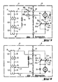
- FIG. 5 A further exemplary embodiment of the battery-operated device according to the invention is shown in FIG. 5.
- the same elements as in FIGS. 2 to 4 are provided with the same reference numerals.
- a changeover switch 32 which is controlled by a relay 33. More specifically, here a common contact connection 32c of the changeover switch 32 is connected via the connector 20 to a connection of the DC motor 22, the other connection of which is connected to the first contact connection 24a of the first switch 24.
- a changeover contact connection 32a of the switch 32 is connected to the intermediate tap 17 via a fuse 34 and a resistor 35, while another changeover contact connection 32b of the changeover switch 32 is connected to the end tap 15 and via the relay 33 and the connecting plug 19 to a contact connection 25a of second switch 25 is connected.
- the further contact connections 24b and 25b are connected to one another and via the connecting plug 21 to the battery end tap 16, which has positive polarity.
- a freewheeling diode 36 is located parallel to the DC motor 22.
- the push button 26 is only slightly actuated, only the first switch 24 is initially closed.
- the DC motor then receives a lower operating voltage, which corresponds to the battery voltage between the intermediate tap 17 and the battery end tap 16.
- a current flows from the battery end tap 16 via the connector 21, the first switch 24, the DC motor 22 and the contact connections 32c and 32a of the changeover switch 32 and also via the fuse 34 and the resistor 35 back to the intermediate tap 17.
- the DC motor 22 then rotates at a low speed.
- the switch device 23 If the switch device 23 is pressed fully, the second switch 25 finally closes, while the first switch 24 remains in the closed state. Due to the closed second switch 25, the full battery voltage between the end taps 15 and 16 reaches the relay coil 33, so that the relay coil 33 picks up. The relay switch 32 is switched over so that its contact connections 32b and 32c are now bridged.
- the DC motor 22 now also receives the full battery voltage, which lies between the end taps 15 and 16, so that a current, starting from the end tap 16, via the connector 21, the first switch 24, the DC motor 22 and the changeover switch 32 to the end tap 15 flows.
- the DC motor 22 is now rotating at a higher rate Rotational speed. During the brief current interruption when switching from 32a to 32b, the freewheeling diode 36 takes over the current flow.
- the changeover switch 32 is constructed in such a way that contact overlap never occurs between the contact connections 32a and 32b.
- the freewheeling diode 36 is polarized in such a way that it ensures an uninterrupted current flow in the DC motor when switching from the contact connection 32a to the contact connection 32b and at the same time also supports arcing between these contact connections. More specifically, the cathode of the diode 36 is connected to the contact terminal 24a of the first switch 24 and the anode of the diode 36 to the connector 20.
- the protective resistor 35 limits a current in the event that an arc still remains between the contact connections 32a and 32b. Should this current assume a value that is too large, the fuse 34 ensures an interruption of the circuit.
- the changeover switch 32 can also be implemented as an electronic switch, for example by means of transistors or thyristors, which are then controlled by a control stage instead of the relay coil when the second switch 25 is closed.
- the DC motor 22 with a freewheeling diode 36 lying in parallel also lie between the connector plug 21 and a node 37, to which the contact connections 25b and 24b of the switches 25 and 24 are connected.
- FIG. 6 A further exemplary embodiment of a battery-operated device according to the invention is shown in FIG. 6.
- the end tap 15 of the battery 9 is connected to the contact terminal 25a of the second switch 25 via the connector 19.
- the intermediate tap 17 is connected via the resistor 35, the fuse 34 and the connector 20 to the contact terminal 24a of the first switch 24.
- Both contact connections 24b and 25b of the first and second switches 24, 25 are connected to one connection of the DC motor 22, the other connection of which is connected via the connector 21 to the battery end tap 16, which has positive polarity.
- the freewheeling diode 36 is in turn parallel to the DC motor 22.
- the switch device 23 If the switch device 23 is first pressed in slightly by the pusher 26, the first switch 24 closes first.
- the DC motor 22 then operates at a low speed, since only the lower battery voltage is supplied to it. A current therefore flows from the battery end tap 16 via the connector 21, the DC motor 22, the first switch 24, the connector 20, the fuse 34 and the resistor 35 back to the intermediate tap 17.
- the first switch 24 is first opened again before the second switch 25 closes.
- the second switch 25 closes abruptly after the first switch 24 has been opened securely.
- the first switch 14 thus has only one wiping contact.
- the DC motor 22 After closing the second switch 25, the DC motor 22 receives the full battery voltage between the end taps 15 and 16 and therefore rotates at high speed. A current now flows from the end tap 16 via the connector 20, the DC motor 22, the second switch 25 and the connector 19 back to the end tap 15.
- the freewheeling diode 36 ensures an uninterrupted current flow in the motor and also supports the arc quenching in the area of the switch device 23.
- the resistor 35 serves to limit the current in the event of a conductive connection between the contact connections 24a and 25a via the switch device 23, the fuse 34 interrupting the line branch in the event of an excessive current flow.
- the inrush current can also be reduced in the start-up phase, thereby protecting switches, switching relays or contact connections and battery cells. Furthermore, the risk of irreversible field damage by switching on the device at low temperatures is reduced.
Landscapes
- Engineering & Computer Science (AREA)
- Power Engineering (AREA)
- Control Of Direct Current Motors (AREA)
- Drilling And Boring (AREA)
- Charge And Discharge Circuits For Batteries Or The Like (AREA)
- Secondary Cells (AREA)
Applications Claiming Priority (2)
| Application Number | Priority Date | Filing Date | Title |
|---|---|---|---|
| DE4009402 | 1990-03-23 | ||
| DE4009402A DE4009402A1 (de) | 1990-03-23 | 1990-03-23 | Batteriebetriebene einrichtung |
Publications (3)
| Publication Number | Publication Date |
|---|---|
| EP0448505A2 true EP0448505A2 (fr) | 1991-09-25 |
| EP0448505A3 EP0448505A3 (en) | 1993-01-20 |
| EP0448505B1 EP0448505B1 (fr) | 1995-10-18 |
Family
ID=6402931
Family Applications (1)
| Application Number | Title | Priority Date | Filing Date |
|---|---|---|---|
| EP91810044A Expired - Lifetime EP0448505B1 (fr) | 1990-03-23 | 1991-01-21 | Dispositif entraîné pour une batterie |
Country Status (4)
| Country | Link |
|---|---|
| US (1) | US5097184A (fr) |
| EP (1) | EP0448505B1 (fr) |
| JP (1) | JPH04251595A (fr) |
| DE (2) | DE4009402A1 (fr) |
Cited By (1)
| Publication number | Priority date | Publication date | Assignee | Title |
|---|---|---|---|---|
| EP1698040A1 (fr) * | 2003-12-05 | 2006-09-06 | Precursor Engineering Pty Ltd | Machine electrique cc commutee |
Families Citing this family (12)
| Publication number | Priority date | Publication date | Assignee | Title |
|---|---|---|---|---|
| US6422330B1 (en) * | 1999-10-04 | 2002-07-23 | Pic Switches, Inc. | Switch for use in ride-on vehicles for children |
| ITVA20010022A1 (it) * | 2001-07-11 | 2003-01-11 | Chemieco Srl | Invertitore statico di tensione per sistema a batterie |
| ITVA20010041A1 (it) * | 2001-11-16 | 2003-05-16 | Chemieco Srl | Sistema di accumulo e/o trasformazione di energia da sorgenti a tensione e frequenza mutevoli |
| US6909201B2 (en) * | 2003-01-06 | 2005-06-21 | General Motors Corporation | Dual voltage architecture for automotive electrical systems |
| US6957645B1 (en) * | 2004-01-21 | 2005-10-25 | Wade Shields | Play enhancement system for a pneumatic projectile launcher and method for enhancing play |
| JP2007015045A (ja) * | 2005-07-06 | 2007-01-25 | Nidec Shibaura Corp | コードレス電動工具 |
| KR100887063B1 (ko) * | 2007-05-14 | 2009-03-04 | 삼성전기주식회사 | 시스템 온 칩(soc)의 전원 공급 장치 |
| US7825615B2 (en) | 2007-10-16 | 2010-11-02 | Glj, Llc | Intelligent motorized appliances with multiple power sources |
| DE102008042799A1 (de) * | 2008-10-13 | 2010-04-15 | Robert Bosch Gmbh | Schalteranordnung, elektrischer Verbraucher sowie Werkzeugmaschine |
| DE102009041878A1 (de) * | 2009-09-07 | 2011-03-10 | C. & E. Fein Gmbh | Steuerbarer Gleichstrom-Motor mit modifizierter Kennlinie |
| DE102010063783A1 (de) * | 2010-12-21 | 2012-06-21 | Endress + Hauser Process Solutions Ag | Feldgerät mit einer Batterieeinheit |
| US20130099574A1 (en) * | 2011-10-24 | 2013-04-25 | Richard Scott Bourgeois | System and method for multiple power supplies |
Citations (4)
| Publication number | Priority date | Publication date | Assignee | Title |
|---|---|---|---|---|
| US2353410A (en) * | 1941-12-04 | 1944-07-11 | Marshall William James | Switching arrangement for employing rectifiers in conjunction with battery regulating switches |
| BE674057A (fr) * | 1965-03-19 | 1966-04-15 | ||
| GB1395508A (en) * | 1971-11-17 | 1975-05-29 | Tower Housewares Ltd | Battery-powered electrical apparatus |
| DE2851841A1 (de) * | 1978-11-30 | 1980-06-12 | Outboard Marine Corp | Erregerschaltung fuer einen gleichstrommotor |
Family Cites Families (11)
| Publication number | Priority date | Publication date | Assignee | Title |
|---|---|---|---|---|
| US635139A (en) * | 1899-08-04 | 1899-10-17 | Martin T A Kubierschky | Regulating electric motors. |
| US2387262A (en) * | 1944-08-25 | 1945-10-23 | Westinghouse Electric Corp | Control system |
| US3336516A (en) * | 1965-02-15 | 1967-08-15 | Ite Circuit Breaker Ltd | Control circuit for d-c motors having dual series field windings |
| US4296363A (en) * | 1974-09-09 | 1981-10-20 | Outboard Marine Corporation | Speed selection for a direct current permanent magnet motor |
| US3984744A (en) * | 1974-09-26 | 1976-10-05 | Moody Warren E | D.C. voltage control system |
| GB1545202A (en) * | 1975-02-28 | 1979-05-02 | Lucas Industries Ltd | Control circuits for electrically driven vehicles |
| US4406982A (en) * | 1981-11-12 | 1983-09-27 | T. & L. Enterprises, Inc. | DC Motor control circuit |
| US4465958A (en) * | 1982-04-26 | 1984-08-14 | Allied Corporation | Motor speed control circuit |
| US4639646A (en) * | 1985-02-04 | 1987-01-27 | Kransco Manufacturing, Inc. | Two pedal, three-way control for child's riding toy |
| GB2204287B (en) * | 1987-03-31 | 1991-04-17 | Hitachi Ltd | Electric power steering control system |
| US4788480A (en) * | 1987-08-07 | 1988-11-29 | Tennant Company | Voltage control for battery powered motor or the like |
-
1990
- 1990-03-23 DE DE4009402A patent/DE4009402A1/de not_active Withdrawn
-
1991
- 1991-01-21 EP EP91810044A patent/EP0448505B1/fr not_active Expired - Lifetime
- 1991-01-21 DE DE59106697T patent/DE59106697D1/de not_active Expired - Lifetime
- 1991-03-22 JP JP3081225A patent/JPH04251595A/ja active Pending
- 1991-03-25 US US07/674,568 patent/US5097184A/en not_active Expired - Fee Related
Patent Citations (4)
| Publication number | Priority date | Publication date | Assignee | Title |
|---|---|---|---|---|
| US2353410A (en) * | 1941-12-04 | 1944-07-11 | Marshall William James | Switching arrangement for employing rectifiers in conjunction with battery regulating switches |
| BE674057A (fr) * | 1965-03-19 | 1966-04-15 | ||
| GB1395508A (en) * | 1971-11-17 | 1975-05-29 | Tower Housewares Ltd | Battery-powered electrical apparatus |
| DE2851841A1 (de) * | 1978-11-30 | 1980-06-12 | Outboard Marine Corp | Erregerschaltung fuer einen gleichstrommotor |
Cited By (2)
| Publication number | Priority date | Publication date | Assignee | Title |
|---|---|---|---|---|
| EP1698040A1 (fr) * | 2003-12-05 | 2006-09-06 | Precursor Engineering Pty Ltd | Machine electrique cc commutee |
| EP1698040A4 (fr) * | 2003-12-05 | 2008-12-31 | Precursor Engineering Pty Ltd | Machine electrique cc commutee |
Also Published As
| Publication number | Publication date |
|---|---|
| DE4009402A1 (de) | 1991-09-26 |
| JPH04251595A (ja) | 1992-09-07 |
| EP0448505A3 (en) | 1993-01-20 |
| EP0448505B1 (fr) | 1995-10-18 |
| US5097184A (en) | 1992-03-17 |
| DE59106697D1 (de) | 1995-11-23 |
Similar Documents
| Publication | Publication Date | Title |
|---|---|---|
| EP0423885B1 (fr) | Dispositif d'alimentation avec limitation du courant d'appel | |
| DE3215147C2 (fr) | ||
| DE19824283B4 (de) | Stromsteuerungsschaltkreis | |
| EP0448505B1 (fr) | Dispositif entraîné pour une batterie | |
| DE3734989A1 (de) | Gleichstromleitungsunterbrecher und verfahren zu dessen kommutierung | |
| DE2135494A1 (de) | Schutzschaltung für einen statischen Schalter | |
| DE19800049A1 (de) | Anordnung zum Übertragen von Daten und/oder Energie mit Trenneinheit | |
| DE69510717T2 (de) | Überstromschutzvorrichtung | |
| DE3045715C2 (de) | Fernsteuerbares nachrichtentechnisches Gerät | |
| EP0025913A2 (fr) | Circuit de sécurité pour la surveillance de soupapes magnétiques de véhicules | |
| DE69702869T2 (de) | Sicherheitsrelais | |
| DE2019184C3 (de) | Starkstromschalteinrichtung | |
| EP0594115B1 (fr) | Méthode pour fonctionnement d'un moteur électrique freiné électriquement et circuit de freinage associé | |
| DE19750958C2 (de) | Schaltungsanordnung zur manuellen oder automatischen Steuerung von zumindest einem Freigabepfad | |
| DE1233475B (de) | Elektronischer UEberstromausschalter | |
| BE1031301B1 (de) | Schaltgerät zum elektrischen Ein- und Ausschalten einer mit einer Gleichspannungs-Versorgungseinrichtung verbindbaren elektrischen Last | |
| DE2713310C3 (de) | Schutzanordnung für eine Niederspannungs-Steuerschaltung | |
| EP0090336B1 (fr) | Circuit pour décharger des condensateurs à l'aide d'un relais | |
| DE102023102236A1 (de) | Schaltgerät zum elektrischen Ein- und Ausschalten einer mit einer Gleichspannungs-Versorgungseinrichtung verbindbaren elektrischen Last | |
| DE2438149A1 (de) | Schaltungsanordnung zum schutz elektrischer akkumulatoren vor tiefentladung | |
| DE4116947C2 (de) | Koppelrelaisschaltung | |
| DE3801875C2 (fr) | ||
| DE2602910C2 (de) | Elektrische Sicherheitsschaltung von Maschinen | |
| DE2419610C3 (de) | Elektrischer Leistungsschalter mit einer Einschaltsperre und einem Sekundärauslöser | |
| EP0807948A2 (fr) | Circuit pour répondre à une pente négative |
Legal Events
| Date | Code | Title | Description |
|---|---|---|---|
| PUAI | Public reference made under article 153(3) epc to a published international application that has entered the european phase |
Free format text: ORIGINAL CODE: 0009012 |
|
| AK | Designated contracting states |
Kind code of ref document: A2 Designated state(s): CH DE FR GB LI |
|
| PUAL | Search report despatched |
Free format text: ORIGINAL CODE: 0009013 |
|
| AK | Designated contracting states |
Kind code of ref document: A3 Designated state(s): CH DE FR GB LI |
|
| 17P | Request for examination filed |
Effective date: 19930220 |
|
| 17Q | First examination report despatched |
Effective date: 19940818 |
|
| GRAA | (expected) grant |
Free format text: ORIGINAL CODE: 0009210 |
|
| AK | Designated contracting states |
Kind code of ref document: B1 Designated state(s): CH DE FR GB LI |
|
| GBT | Gb: translation of ep patent filed (gb section 77(6)(a)/1977) |
Effective date: 19951024 |
|
| REF | Corresponds to: |
Ref document number: 59106697 Country of ref document: DE Date of ref document: 19951123 |
|
| ET | Fr: translation filed | ||
| PLBE | No opposition filed within time limit |
Free format text: ORIGINAL CODE: 0009261 |
|
| STAA | Information on the status of an ep patent application or granted ep patent |
Free format text: STATUS: NO OPPOSITION FILED WITHIN TIME LIMIT |
|
| 26N | No opposition filed | ||
| PGFP | Annual fee paid to national office [announced via postgrant information from national office to epo] |
Ref country code: FR Payment date: 19981217 Year of fee payment: 9 |
|
| PGFP | Annual fee paid to national office [announced via postgrant information from national office to epo] |
Ref country code: GB Payment date: 19990111 Year of fee payment: 9 |
|
| PG25 | Lapsed in a contracting state [announced via postgrant information from national office to epo] |
Ref country code: GB Free format text: LAPSE BECAUSE OF NON-PAYMENT OF DUE FEES Effective date: 20000121 |
|
| GBPC | Gb: european patent ceased through non-payment of renewal fee |
Effective date: 20000121 |
|
| PG25 | Lapsed in a contracting state [announced via postgrant information from national office to epo] |
Ref country code: FR Free format text: LAPSE BECAUSE OF NON-PAYMENT OF DUE FEES Effective date: 20000929 |
|
| REG | Reference to a national code |
Ref country code: FR Ref legal event code: ST |
|
| PGFP | Annual fee paid to national office [announced via postgrant information from national office to epo] |
Ref country code: CH Payment date: 20050117 Year of fee payment: 15 |
|
| PG25 | Lapsed in a contracting state [announced via postgrant information from national office to epo] |
Ref country code: CH Free format text: LAPSE BECAUSE OF NON-PAYMENT OF DUE FEES Effective date: 20060131 Ref country code: LI Free format text: LAPSE BECAUSE OF NON-PAYMENT OF DUE FEES Effective date: 20060131 |
|
| REG | Reference to a national code |
Ref country code: CH Ref legal event code: PL |
|
| PGFP | Annual fee paid to national office [announced via postgrant information from national office to epo] |
Ref country code: DE Payment date: 20091224 Year of fee payment: 20 |
|
| PG25 | Lapsed in a contracting state [announced via postgrant information from national office to epo] |
Ref country code: DE Free format text: LAPSE BECAUSE OF EXPIRATION OF PROTECTION Effective date: 20110121 |