EP0447214A2 - Kompatibles Fernsehsystem mit komprimiertem Zusatzsignal - Google Patents
Kompatibles Fernsehsystem mit komprimiertem Zusatzsignal Download PDFInfo
- Publication number
- EP0447214A2 EP0447214A2 EP91302125A EP91302125A EP0447214A2 EP 0447214 A2 EP0447214 A2 EP 0447214A2 EP 91302125 A EP91302125 A EP 91302125A EP 91302125 A EP91302125 A EP 91302125A EP 0447214 A2 EP0447214 A2 EP 0447214A2
- Authority
- EP
- European Patent Office
- Prior art keywords
- signal
- auxiliary
- interpolating
- output
- field
- Prior art date
- Legal status (The legal status is an assumption and is not a legal conclusion. Google has not performed a legal analysis and makes no representation as to the accuracy of the status listed.)
- Withdrawn
Links
- 230000002123 temporal effect Effects 0.000 description 21
- 238000010586 diagram Methods 0.000 description 19
- 238000001228 spectrum Methods 0.000 description 16
- 230000000750 progressive effect Effects 0.000 description 14
- 238000006243 chemical reaction Methods 0.000 description 11
- 238000012360 testing method Methods 0.000 description 9
- 238000012545 processing Methods 0.000 description 6
- 238000010276 construction Methods 0.000 description 5
- 238000000034 method Methods 0.000 description 5
- 238000011045 prefiltration Methods 0.000 description 5
- 230000015556 catabolic process Effects 0.000 description 4
- 238000006731 degradation reaction Methods 0.000 description 4
- 230000006866 deterioration Effects 0.000 description 4
- 230000005540 biological transmission Effects 0.000 description 3
- 239000002131 composite material Substances 0.000 description 2
- 230000007547 defect Effects 0.000 description 2
- 238000012986 modification Methods 0.000 description 2
- 230000004048 modification Effects 0.000 description 2
- 238000012935 Averaging Methods 0.000 description 1
- 230000003044 adaptive effect Effects 0.000 description 1
- 239000000463 material Substances 0.000 description 1
- 230000015654 memory Effects 0.000 description 1
- 238000000926 separation method Methods 0.000 description 1
Images


Classifications
-
- H—ELECTRICITY
- H04—ELECTRIC COMMUNICATION TECHNIQUE
- H04N—PICTORIAL COMMUNICATION, e.g. TELEVISION
- H04N7/00—Television systems
- H04N7/015—High-definition television systems
-
- H—ELECTRICITY
- H04—ELECTRIC COMMUNICATION TECHNIQUE
- H04N—PICTORIAL COMMUNICATION, e.g. TELEVISION
- H04N11/00—Colour television systems
- H04N11/24—High-definition television systems
- H04N11/30—High-definition television systems with transmission of the extra information by means of quadrature modulation
-
- H—ELECTRICITY
- H04—ELECTRIC COMMUNICATION TECHNIQUE
- H04N—PICTORIAL COMMUNICATION, e.g. TELEVISION
- H04N7/00—Television systems
- H04N7/01—Conversion of standards, e.g. involving analogue television standards or digital television standards processed at pixel level
- H04N7/0117—Conversion of standards, e.g. involving analogue television standards or digital television standards processed at pixel level involving conversion of the spatial resolution of the incoming video signal
- H04N7/012—Conversion between an interlaced and a progressive signal
-
- Y—GENERAL TAGGING OF NEW TECHNOLOGICAL DEVELOPMENTS; GENERAL TAGGING OF CROSS-SECTIONAL TECHNOLOGIES SPANNING OVER SEVERAL SECTIONS OF THE IPC; TECHNICAL SUBJECTS COVERED BY FORMER USPC CROSS-REFERENCE ART COLLECTIONS [XRACs] AND DIGESTS
- Y10—TECHNICAL SUBJECTS COVERED BY FORMER USPC
- Y10S—TECHNICAL SUBJECTS COVERED BY FORMER USPC CROSS-REFERENCE ART COLLECTIONS [XRACs] AND DIGESTS
- Y10S348/00—Television
- Y10S348/904—Separation or joining of side and center panels
Definitions
- the present invention relates generally to a television system, and more particularly to a compatible television system with conpanding auxiliary signal.
- a conventional television receiver such as a receiver in accordance with NTSC broadcast standards adopted in the United States, Japan and elsewhere, has a 4:3 aspect ratio (the ratio of the width to the height of a displayed image).
- Video information signals with a 5:3 aspect ratio have received particular attention since this ratio approximates that of motion picture film, and thus such signals can be transmitted and received without cropping the image information.
- wide aspect television systems which simply transmit signals having an increased aspect ratio as compared to conventional systems are incompatible with conventional aspect ratio receivers. This makes widespread adoption of wide aspect television systems difficult.
- FIGURE 1 shows again the compatible wide aspect television system disclosed in the U.S. Patent 4,855,824.
- 1201 is an original wide aspect progressive-scan signal with the aspect ratio 16:9 or 5:3.
- This signal 1201 is comprised of left, right and center panel information and processed so as to develop four separate encoding components 1202, 1205, 1209 and 1210.
- the first component 1202 contains time expanded center panel information and time compressed side panel information of low frequency.
- the second component 1205 contains time expanded side panel information of high frequency.
- the third component 1209 contains high frequency luminance information.
- the fourth component 1210 contains vertical temporal helper information of high frequency.
- the center panel information in the first component 1202 does not cause a pattern distortion when decoded on a standard television receiver because it has been time expanded. Further, the side panel information of the first component 1202 is multiplexed to the horizontal over-scan regions where such information is hidden from view in a standard television receiver image display.
- the side panel information in the second component 1205 is time expanded four times. Therefore, the band of the second component 1205 is compressed to 1/4. As will be described later, the present invention is intended to improve the first and second components 1202 and 1205.
- the second component 1205 is processed in an intraframe averager circuit 1206.
- a resulting intra-frame average signal output from the intra-frame averager circuit 1206 is converted into a progressive scan format signal.
- This output is quadrature modulated (frequency shift modulated) with the third component 1209, which has been inter-frame averaged, by a quadrature modulator 1207.
- the main signal i.e., the first component 1202 is also intra-frame averaged in an intra-frame averager circuit 1203.
- This main signal 1202 is added to a carrier signal from the quadrature modulator 1207 by the adder 1204 and the added output becomes a transmission signal via the quadrature modulator 1208.
- the reason for summing of the main signal 1202 in the frames is to facilitate separation of the main signal 1202 from the side panel high-pass signal 1205 at the receiving side. Further, the quadrature modulator 1207 reverses carrier phase between lines.
- FIGURE 2 is a diagram for illustrating the process of intra-frame averaging in the context of the system of FIGURE 1.
- pairs of pixels 262H apart within a frame i.e., pixels in different fields of the same field of the first component 1202 are averaged.
- a pair of original pixels Y1+C1 and Y2+C2 are averaged.
- the pixels in the different fields of the averaged frame e.g., 1303 have the same value.
- the averaged values X1, X3 in the frame 1304 are quadrature modulated in the quadrature modulator 1305 (equivalent to the quadrature modulator 1208 shown in FIGURE 2).
- the modulated signals in adjacent lines of the same frame 1306 become opposite in phase, as shown by -A1 and A1.
- the signal 1306 is added to the signal 1303 in the adder 1308.
- a resulting output signal 1307 becomes M1-A1 in the first field and M1+A1 in the second field.
- the main signal M can be restored by summing the signals in the different fields, while the side panel high-pass component A can be restored by subtracting them.
- FIGURE 3 shows the construction of the encoder and 1405 is a terminal to which the main signal 1202 is led. From the signal from the terminal 1405, a signal in the area to which auxiliary signal (the side band high-pass component) is multiplexed by the band-pass filter (BPF) 1406 is extracted. The inter-field sum of this signal in the multiplex area is performed by the intra-frame averager circuit composed of the field delay unit 1408 and the adder 1409. The inter-field sum output from the adder 1409 is progressively scanned by the selector 1412. The output of the selector 1412 is added to a signal outside the multiplex area from the one field delay unit 1411. The signal outside the multiplex area is a signal from the adder 1407 which adds the main signal 1201 to a signal passed through the band-pass filter 1406.
- BPF band-pass filter
- Another input terminal 1401 receives the time expanded side panel high-pass component signal 1205.
- the inter-field summing of the signal from the terminal 1401 is carried out by the field delay unit 1416 and the adder 1417.
- the interfield summed output from the adder 1417 is converted into a progressive-scan format by the field delay unit 1418 and the selector 1419.
- the progressive-scan format signal is frequency shifted to the multiplex area through the modulator 1420.
- the phase of the signal shifted to the multiplex area is reversed for every line by the phase reversing circuit 1403 and the selector 1404.
- This phase reversed output from the selector 1404 is input to the adder 1414 where it is added to the main signal with the side panel signal from the adder 1413 added.
- the phase reversed output from the selector 1404 is a signal equivalent to the frame signal 1303 shown in FIGURE 2.
- the auxiliary signal multiplexed output from the adder 1414 is obtained at the output terminal 1415.
- FIGURE 4 shows the construction of the decoder.
- the auxiliary signal multiplexed output from the output terminal 1415 is fed to the terminal 1501.
- the signal from the multiplex area is extracted at the terminal 1501 by the band-pass filter 1502.
- the inter-field difference and sum calculations are carried out for the signal from the bandpass filter by the field delay unit 1505 and the adders 1506 and 1507.
- the difference signal encoded from the adder 1506 is the side panel high-pass component of with its phase reversed between the fields.
- This signal is demodulated by the demodulator 1508.
- the summed signal output from the adder 1507 is the multiplex area signal of the main signal with the side panel high-pass component removed.
- This signal is input into the adder 1511 after being processed by the field delay unit 1509 and the selector 1510 and added to the signal outside the multiplex area from the field delay unit 1504.
- the main signal with the side panel low-pass component superposed on the horizontal over-scanning area is obtained at the output terminal 1513.
- the main signal outside the multiplex area is output by the adder 1503 which adds up the output of the band-pass filter 1502 and the signal from the terminal 1501.
- auxiliary signals it is possible to perform the multiplex transmission of auxiliary signals by performing inter-field summing and processing.
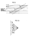
- multiplex transmission of auxiliary signals according to this system deteriorates a smooth oblique line into a zigzag line on the image display by the vertical aliasing distortion as shown in FIGURE 5.
- the phenomenon on the edge is produced because the first field signal is also used in the second field. It is seen that on the encoder shown in FIGURE 3, the edge part is made obscure through the inter-field summing by the field delay unit 1408 and the adder 1409 but it cannot be thoroughly improved. Even when a pre-filter (vertical LPF) having a steep frequency characteristic is used instead of the inter-field summing, the zigzag deterioration is caused in accordance with the progressive-scan format conversion.
- a pre-filter vertical LPF
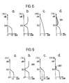
- FIGURES 6(a) through 6(d) illustrate the phenomenon produced at the edge in terms of spectrum.
- the ordinate represents the number of vertical scanning lines and the abscissa represents gains.
- FIGURE 6(a) When the vertical band is limited to 240 lines in advance by a vertical pre-filter, vertical spectra are expressed as shown in FIGURE 6(a).
- the signal having this spectrum produces the folded component as shown in FIGURE 6(b) (the output from the adder 1409). If the progressive-scan format conversion is carried out for such a signal at the receiving side, the result would become the same when a vertical interpolating filter-shown in FIGURE 6(c) was used and the signal obtained from the terminal 1512 or 1513 presents the spectrum shown in FIGURE 6(d).
- the oblique lined section 9001 is left as the folded component, causing notches.
- the present invention therefore seeks to provide a compatible television system with companding of auxiliary signal which is able to prevent a deterioration of the picture caused by multiplexing auxiliary information on the television signal.
- a compatible television signal encoder includes a divider for dividing the wide aspect television signal into a main signal having the first signal and low-frequency components of the second signal multiplexed in the horizontal overscan regions of the first signal and an auxiliary signal, an interpolator for producing an interpolating scanning field signal using a first scanning field signal of the main signal output from the divider, a field switch for replacing a second scanning field signal of the main signal with the interpolating scanning field signal output from the interpolator and an adder for adding the auxiliary signal from the divider to the signal output from the field switch.
- a compatible television signal decoder includes an interpolator for producing a compensating field signal using the first scanning field signal of the television signal, a first adder for separating the auxiliary signal by subtracting the compensating field signal output from the interpolator from the second field signal output from the television signal, a frequency demodulator for shifting the auxiliary signal to the original frequency and a second adder for adding the second scanning field signal of the television signal and the compensating field signal output from the interpolator.
- FIGURES 7 through 27 The present invention will be described in detail with reference to the FIGURES 7 through 27.
- reference numerals or letters used in FIGURES 1 through 6 will be used to designate like or equivalent elements for simplicity of explanation.
- FIGURES 7 and 8 a first embodiment of the auxiliary signal multiplexed television system according to the present invention will be described in detail.
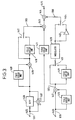
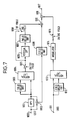
- FIGURE 7 is a block diagram showing an embodiment of the auxiliary signal multiplexed television signal encoder involved in the present invention.
- the main signal 1202 (see FIGURE 2) with the low-pass component of the side panel information which was time compressed and multiplexed in the horizontal over-scanning area is led to the terminal 1000.
- the signal from terminal 1000 is input to a pre-filter (a temporal vertical LPF processing block) composed of the field delay unit 1003 and the vertical LPF 1004 through the band-pass filter (BPF) 1001 which allows a signal of an area to which the auxiliary signal (the side band high-pass component) is multiplexed to pass.
- This pre-filter limits the vertical band of the signal from the band-pass filter 1001 to 240 lines.
- the signal of the first field only is selected by the switch 1005 for the output from the vertical LPF 1004.
- Signals from the switch 1005 are divided into signals to be induced into the vertical interpolating filter (IPF) 1006 and signals to be induced into the first input terminal of the selector 1008.
- the signal induced into the vertical interpolating filter 1006 is led to the second input terminal of the selector 1008 through the field delay unit 1007.
- the selector 1008 selects the second field signal produced through interpolation from the field delay unit 1007 after selecting the first field signal induced into the first input terminal.
- the output signal from the selector 1008 is input into the adder 1010 and added to the main signal outside the multiplex area from the field delay unit 1009.
- the main signal outside the multiplex area is the signal from the adder 1002 which adds the main signal 1202 end the signal passed through the band-pass filter 1001.
- the 1011 is the terminal to which the signal of the time expanded side panel high-pass component 1205 is provided.
- the vertical band of the signal from the terminal 1011 is limited to 240 lines by a pre-filter composed of the field delay unit 1012 and the vertical LPF 1013.
- Output from the vertical LPF 1013 is input into the adder 1016 through the modulator 1014 and the switch 1015 connected to the second field and the side panel information of the signal from the adder 1010 is added to the main signal multiplexed to one field.
- Auxiliary signal multiplexed output composed of the side panel high-pass signal 1205 and the main signal 1202 is led to the output terminal 1017.
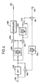
- FIGURE 8 An embodiment of the auxiliary signal multiplexed television signal decoder involved in the present invention is shown in FIGURE 8.
- the auxiliary signal multiplexed output from the sending side output terminal 1017 is led to the terminal 2001.
- the signal from the band-pass filter 2002 is divided into three parts which are induced into the vertical interpolating filter 2004, the first input terminal of the adder 2012, and the first input terminal of the selector 2006, respectively.
- the signal input into the vertical interpolating filter 2004 is led to the second input terminals of the adder 2012 and the selector 2006 through the field delay unit 2005.
- the vertical interpolating filter 2004 interpolates the second field signal from the first field signal and loads the secondary field signal generated through the interpolation into the second input terminal of the adder 2012, and adds the second field signal led to the first input terminal of the adder 2012 and the second field signal generated through the interpolation.
- the auxiliary signal is separated from the second field signal with the auxiliary signal multiplexed at the sending side.
- the auxiliary signal from the adder 2012 is led to the output terminal 2009 through the switch 2007 which is conducted during the second field period and the demodulator 2011.
- the selector 2006 provides the signal from the band-pass filter 2002 in the first field to the adder 2008 as well as the signal in the multiplex area from the delay unit 2005, which is obtained through the interpolation by the vertical interpolating filter 2004 and the signal outside the multiplex area in the second field. These are added to the signal from the delay unit 2013. As a result, the main signal is separated from the adder 2008 and led to the output terminal 2010.
- FIGURE 9 shows spectra at operating points and filter characteristics of the encoder shown in FIGURE 7.
- the spectrum characteristic of the signal from the vertical LPF 1004 is as shown in FIGURE 9 (a) because components of more than 240 lines are eliminated.
- the signal from the vertical LPF 1004 produces the folded component 3003 as shown in FIGURE 9 (b) because the number of scanning lines is reduced to the half by the switch 1005.
- This signal has spectrum with less folded component 3002 as shown in FIGURE 9 (d) by the field interpolating characteristic of the vertical interpolating filter 1006 shown in FIGURE 9 (c). This is clearly seen when compared with the folded spectrum 9001 shown in FIGURE 6.
- the processings described above are performed for the multiplex area components which are output from the band-pass filter 1001, in the horizontal-vertical frequency areas, the spectrum will become as shown in FIGURE 10 (The oblique lined part).
- fl and fn in FIGURE 10 show upper and lower cut-off frequencies of the band-pass filter 101, respectively. Therefore, the auxiliary signal multiplexed output led out of the output terminal 1017 has the spectra 3006 and 3007 shown in FIGURE 10 and becomes a good signal in which the oblique high-frequency band having only visually low contribution is partially eliminated.
- the second field scanning lines shown by 4001 are interpolated by the first field scanning lines m1, m2 and so on shown by 4002.
- the second field scanning lines will be expressed by; (m1 + m2)/2, (m2 + m3)/2, ...
- the auxiliary signal multiplexed signals can be expressed by; (m1 + m2)/2 + a1, (m2 + m3)/2 + a2, ...
- the auxiliary signal multiplexed signals will become as follows as shown by 4004 because differences of the second field are taken after interpolation using the first field scanning lines m1, m2, ... shown by 4003 in FIGURE 11; (m1 + m2)/2 + a1 - (m1 + m2)/2, (m2 + m3)/2 + a2 - (m2 + m3)/2, ... ...
- auxiliary signals a1, a2 ?? crosstalk does not become a problem. Further, in the case of receiving by a standard television receiver, it is possible to prevent occurrence of jammings such as flicker, etc.
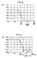
- FIGURE 12 shows the vertical interpolating filter characteristic when the interpolation was made using two lines between the upper and lower scanning lines described above.
- the abscissa shows the number of scanning lines and the ordinate shows level.
- the number of scanning lines is approximately 180 lines and the interpolation without attenuation is possible.
- the interpolation may be performed by 10 scanning lines as shown in FIGURE 13.
- FIGURE 14 shows the filter characteristic in this case. It can be seen that the number of scanning lines is approximately 240 lines and it is possible to perform the interpolation without causing attenuation.
- FIGURES 15 and 16 shown an embodiment of the present invention where the present invention has been applied to a system which encodes auxiliary signal multiplexed television signals together with color difference signals.
- the block 700 enclosed by a dotted line at the sending side in FIGURE 15 is the same as the encoder shown in FIGURE 7.
- Main signal, auxiliary signal and color difference signals I and Q are induced into the input terminals 701, 702, 703 and 704, respectively.
- the main signal and auxiliary signal are encoded through the processing described above and the encoded and acquired luminance signal is input into the NTSC encoder 706.
- the cut-off frequency at the upper side of the band-pass filter 1001 is set at around 2.0 MHz with no color difference signal component multiplexed (crosstalk removed).
- the color difference signals I and Q are input to the NTSC encoder 706 through the delay circuit 705 and multiplexed to the auxiliary signal multiplexed luminance signal.
- the outputs from the NTSC encoder 706 are output from the output terminal 707 as composite color television signals.
- the block 800 enclosed by a dotted line at the receiving side shown in FIGURE 16 is a decoder of the same construction as that shown in FIGURE 8.
- the composite color TV signals from the sending side are led to the terminal 801 and decoded to NTSC color signals by the NTSC decoder 802.
- the decoded color difference signals are output from the output terminals 805 and 806 as the color difference signals I and Q, respectively.
- the decoder 800 leads auxiliary signal and luminance signal (main signal) Y to the output terminals 803 and 804.
- the interpolation was performed based on the first field scanning lines in the embodiment of the present invention, it is needless to say that the interpolation can be performed by the second field scanning lines.
- the first and second fields referred to in the claims of the present invention do not mean the first and second fields in a general means but mean that when either one of two fields is called the first field, the other is called the second filed.
- the second field signal is interpolated from the first field using a vertical interpolating filter and auxiliary signal is produced by negating the interpolated signal multiplexed in the second field.
- Another embodiment of the present invention takes a form of scan conversion encoder and decoder. This embodiment will be described below.
- FIGURE 17 shows a conventional progressive scan converter.
- An interlace scan signal is converted into a progressive scan signal by a motion adaptive scan line interpolator.
- the scan line interpolator has an intro-field processor, an inter-field processor and a motion detector.
- the inter-field processor interpolates a scan signal from the preceding field signal. It is a temporal low pass filter. Therefore, vertical resolution is not degraded.
- the intra-field processor interpolates scan line signals from a pair of adjacent the two scan line signals in the same field. Therefore, the interpolated scan line signals of motion picture are produced by vertical low pass filter. It limits vertical resolution up to 240 TVL/PH.
- a higher frequency component of the input signal more than 240 TVL/PH causes an aliasing distortion.
- a progressive scan signal has the advantage of vertical and temporal high resolution. It, however, requires twice bandwidth as much as interlace scan signal. A redundant vertical/temporal spectrum of a progressive scan signal is examined by a subjective test.
- FIGURE 19 shows a test set-up for the subjective test.
- a progressive scan monitor (aspect ratio of 16:9) is used for the test.
- HDTV high definition television
- the converted progressive scan signal is decomposed to a frame average signal (temporal low frequency component) and a frame difference signal (temporal high frequency component).
- the frame difference signal is limited up to 2.7 MHz.
- This band-limited signal causes almost no degradation of motion picture.
- It is band-limited by a vertical low pass filter. This filter is designated as 2-dimensional filter as shown in FIGURE 18.
- the invertors evaluated the difference between the band-limited picture and the original progressive scan picture.
- FIGURE 19 The result of the subjective test is shown in FIGURE 19. It shows the vertical component of the temporal high frequency component of the temporal high frequency component can be band-limited up to 240 TVL/PH without degradation of a motion picture.
- FIGURE 19 a mark ⁇ presents the result of the spectrum which is eliminated the diagonal high frequency component as shown in FIGURE 20.
- the degradation of the eliminated spectrum is almost negligible.
- the band-limited signal as shown in FIGURE 20 cannot be directly converted into an interlace scan signal, because the vertical and temporal high frequency component (0-1.35 Mhz, 120-240 TVL/PH, 15-30 Hz) is aliased into the low frequency component.
- a scan converter encodes into the spectrum as shown in FIGURE 21.
- the vertical and temporal high frequency component is multiplexed in the diagonal high frequency region of the temporal low frequency component.
- the encoded signal can be converted into the interlace scan signal without aliasing distortion.
- the temporal high and vertical low frequency component (0-2.7 MHz, 0-120 TVL/PH, 15-30 Hz) is transmitted by the interlace format without aliasing confusion.
- the transmitted interlace scan signal is compatible with existing NTSC receivers.
- the temporal low frequency component is transmitted as shown in FIGURE 22.
- FIGURE 23 shows the principle of the multiplexing process.
- the horizontal high frequency component more than 2 MHz of the second field is interpolated from first field.
- the auxiliary signal M j which is the vertical and temporal high frequency component described above, is multiplexed into the interpolated signal ⁇ h i a i .
- the multiplexed signal ⁇ h i a i +Mj is transmitted.
- the auxiliary signal M j is obtained after subtracting the interpolated signal from the multiplexed signal ⁇ h i a i +M j .
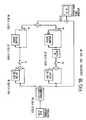
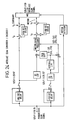
- FIGURE 24 The block diagram of the scan conversion encoder according to the present invention is shown in FIGURE 24.
- An input progressive scan signal is decomposed to the intraframe average signal (temporal low) and the intra-frame difference signal (temporal high). These two decomposed signals are also progressive scan signals. These frame frequencies, however, are 29.97 Hz.
- the intra-frame average signal presents vertical and horizontal resolution and the intra-frame difference signal presents temporal resolution.
- the diagonal high frequency component of the intra-frame difference signal is eliminated by a two dimensional filter as shown in FIGURE 20.
- the intra-frame average signal is band-shaped by the two dimensional low pass filter.
- the intra-frame difference signal is multiplexed into the diagonal high frequency region of the intra-frame average signals as shown in FIGURE 21.
- the intra-frame average signal is transmitted as shown in FIGURE 22.
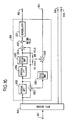
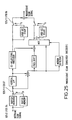
- FIGURE 25 shows a block diagram of the decoder according to the present invention.
- the first and the second fields of the interlace signal are converted to the progressive scan signal with frame frequency 29.97 Hz by the buffer memories.
- the vertical high frequency component (more than 360 TVL/PH) of the signal is separated by the vertical filter.
- the separated signal is the vertical high frequency component.
- the separated signal is shifted to the temporal high frequency region.
- the multiplexed auxiliary signal which is vertical and temporal high frequency component, is de-multiplexed by the de-multiplexing processor. These two signals are processed to the intra-frame difference signal.
- the motion mode or the stationary mode is selected by the mixer circuit.
- the intra-frame average and difference signals are converted to progressive scan signals with frame frequency 59.94 Hz by field repitition. It is noted that the frame difference signal is phase altered by field.
- FIGURE 26 shows the picture reproduced by the conventional scan converter. There is an aliasing distortion caused by the vertical and temporal high frequency component.
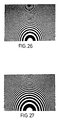
- FIGURE 27 shows the picture reproduced by the scan converter according to the present invention. This scan converter improves the degradation.
- the present invention can provide an extremely preferable compatible auxiliary signal multiplexed television system.
- the present invention extends the diagonal resolution of the side panel signals.
- Horizontal resolution of the center panel signal is also extended up to 6.6. MHz (400 TVL/PH).
- the present invention extends vertical resolution (360 TVL/PH) without aliasing distortion.
Landscapes
- Engineering & Computer Science (AREA)
- Multimedia (AREA)
- Signal Processing (AREA)
- Computer Graphics (AREA)
- Television Systems (AREA)
Applications Claiming Priority (2)
| Application Number | Priority Date | Filing Date | Title |
|---|---|---|---|
| JP63331/90 | 1990-03-13 | ||
| JP2063331A JPH03263987A (ja) | 1990-03-13 | 1990-03-13 | 付加信号多重テレビジョン信号の送信装置及び受信装置 |
Publications (2)
| Publication Number | Publication Date |
|---|---|
| EP0447214A2 true EP0447214A2 (de) | 1991-09-18 |
| EP0447214A3 EP0447214A3 (en) | 1992-12-16 |
Family
ID=13226161
Family Applications (1)
| Application Number | Title | Priority Date | Filing Date |
|---|---|---|---|
| EP19910302125 Withdrawn EP0447214A3 (en) | 1990-03-13 | 1991-03-13 | Compatible television system with companded auxiliary signal |
Country Status (3)
| Country | Link |
|---|---|
| US (1) | US5161003A (de) |
| EP (1) | EP0447214A3 (de) |
| JP (1) | JPH03263987A (de) |
Cited By (1)
| Publication number | Priority date | Publication date | Assignee | Title |
|---|---|---|---|---|
| EP0651568A3 (de) * | 1993-10-29 | 1995-05-24 | Kabushiki Kaisha Toshiba | Signalverarbeitungsvorrichtung zum Umwandlen der Zeilenanzahl eines Fernsehsignals |
Families Citing this family (4)
| Publication number | Priority date | Publication date | Assignee | Title |
|---|---|---|---|---|
| JP3332093B2 (ja) * | 1992-09-04 | 2002-10-07 | 株式会社東芝 | テレビジョン信号処理装置 |
| US6858526B2 (en) * | 1998-07-14 | 2005-02-22 | Micron Technology, Inc. | Methods of forming materials between conductive electrical components, and insulating materials |
| JP4691812B2 (ja) * | 2001-03-29 | 2011-06-01 | ソニー株式会社 | 係数データの生成装置および生成方法、それを使用した情報信号の処理装置および処理方法 |
| JP2005020512A (ja) * | 2003-06-27 | 2005-01-20 | Pioneer Electronic Corp | 映像信号処理装置 |
Family Cites Families (5)
| Publication number | Priority date | Publication date | Assignee | Title |
|---|---|---|---|---|
| DE3304030A1 (de) * | 1983-02-07 | 1984-08-09 | Robert Bosch Gmbh, 7000 Stuttgart | Verfahren und schaltung zur umwandlung eines videosignals einer zeilenzahl in ein videosignal einer anderen zeilenzahl |
| ATE107112T1 (de) * | 1987-09-14 | 1994-06-15 | Gen Electric | Kompatibles fernsehsystem mit kompandierung von hilfsignal kodierter information. |
| GB8721565D0 (en) * | 1987-09-14 | 1987-10-21 | Rca Corp | Video signal processing system |
| US5014116A (en) * | 1988-03-10 | 1991-05-07 | Kabushiki Kaisha Toshiba | Color television system |
| JPH02142288A (ja) * | 1988-11-24 | 1990-05-31 | Hitachi Ltd | 信号処理装置 |
-
1990
- 1990-03-13 JP JP2063331A patent/JPH03263987A/ja active Pending
-
1991
- 1991-03-11 US US07/667,297 patent/US5161003A/en not_active Expired - Fee Related
- 1991-03-13 EP EP19910302125 patent/EP0447214A3/en not_active Withdrawn
Cited By (2)
| Publication number | Priority date | Publication date | Assignee | Title |
|---|---|---|---|---|
| EP0651568A3 (de) * | 1993-10-29 | 1995-05-24 | Kabushiki Kaisha Toshiba | Signalverarbeitungsvorrichtung zum Umwandlen der Zeilenanzahl eines Fernsehsignals |
| US5534935A (en) * | 1993-10-29 | 1996-07-09 | Kabushiki Kaisha Toshiba | Processing apparatus for progressive scan generation of a television signal |
Also Published As
| Publication number | Publication date |
|---|---|
| EP0447214A3 (en) | 1992-12-16 |
| JPH03263987A (ja) | 1991-11-25 |
| US5161003A (en) | 1992-11-03 |
Similar Documents
| Publication | Publication Date | Title |
|---|---|---|
| KR910000548B1 (ko) | 칼라 텔레비젼 표시 장치 | |
| JP2588636B2 (ja) | Ntscテレビジョンとhdテレビジョンの画面信号の互換方法及び装置 | |
| US5161006A (en) | Method for separating chrominance and luminance components of a television signal | |
| US5161003A (en) | Compatible television system with companding auxiliary signal | |
| JPS60158785A (ja) | 画像信号帯域圧縮伝送方式 | |
| JPH0346479A (ja) | テレビジョン信号変換装置 | |
| JPH03220990A (ja) | 画質改善tvシステムにおける垂直高域成分の分離伝送方式 | |
| US5068729A (en) | Compatible extended-definition television | |
| GB2262859A (en) | Letterbox television signal with chrominance helper signal | |
| JP2600446B2 (ja) | 映像信号処理装置 | |
| JP2594596B2 (ja) | 画像信号伝送方式 | |
| JP3278465B2 (ja) | テレビジョン信号処理装置 | |
| JP2751844B2 (ja) | ワイドテレビジョン信号処理装置およびワイドテレビジョン信号受信装置 | |
| JP2848946B2 (ja) | テレビジョン信号処理回路 | |
| JP2928561B2 (ja) | テレビジョン信号の形成方法及び装置 | |
| JPH01253381A (ja) | テレビジョン信号走査変換伝送方法 | |
| JP2855738B2 (ja) | 動画像信号伝送方式 | |
| JPH07327211A (ja) | ワイドテレビジョン信号処理装置 | |
| JPH04322583A (ja) | テレビジョン信号変換装置 | |
| JPH01229584A (ja) | 多重化信号受信装置 | |
| JPH07143258A (ja) | テレビジョン信号処理装置 | |
| JPH0556456A (ja) | 画像信号伝送方法 | |
| Mishina et al. | A study on three-dimensional (spatio-temporal) noise characteristics of letterbox EPITV | |
| JPS63502156A (ja) | テレビジョン信号のための帯域幅圧縮 | |
| JPH0851603A (ja) | テレビジョン受信機 |
Legal Events
| Date | Code | Title | Description |
|---|---|---|---|
| PUAI | Public reference made under article 153(3) epc to a published international application that has entered the european phase |
Free format text: ORIGINAL CODE: 0009012 |
|
| 17P | Request for examination filed |
Effective date: 19910405 |
|
| AK | Designated contracting states |
Kind code of ref document: A2 Designated state(s): DE FR GB |
|
| RAP1 | Party data changed (applicant data changed or rights of an application transferred) |
Owner name: KABUSHIKI KAISHA TOSHIBA Owner name: TOSHIBA AVE CO., LTD |
|
| PUAL | Search report despatched |
Free format text: ORIGINAL CODE: 0009013 |
|
| AK | Designated contracting states |
Kind code of ref document: A3 Designated state(s): DE FR GB |
|
| R17P | Request for examination filed (corrected) |
Effective date: 19910405 |
|
| K1C1 | Correction of patent application (title page) published |
Effective date: 19910918 |
|
| STAA | Information on the status of an ep patent application or granted ep patent |
Free format text: STATUS: THE APPLICATION HAS BEEN WITHDRAWN |
|
| 18W | Application withdrawn |
Withdrawal date: 19931215 |