EP0446934B1 - Verfahren zur Herstellung von Kompositmaterial - Google Patents
Verfahren zur Herstellung von Kompositmaterial Download PDFInfo
- Publication number
- EP0446934B1 EP0446934B1 EP91103974A EP91103974A EP0446934B1 EP 0446934 B1 EP0446934 B1 EP 0446934B1 EP 91103974 A EP91103974 A EP 91103974A EP 91103974 A EP91103974 A EP 91103974A EP 0446934 B1 EP0446934 B1 EP 0446934B1
- Authority
- EP
- European Patent Office
- Prior art keywords
- substep
- porosity
- powder
- sub
- fabricating method
- Prior art date
- Legal status (The legal status is an assumption and is not a legal conclusion. Google has not performed a legal analysis and makes no representation as to the accuracy of the status listed.)
- Expired - Lifetime
Links
- 239000002131 composite material Substances 0.000 title claims description 33
- 238000004519 manufacturing process Methods 0.000 title claims description 9
- 239000000463 material Substances 0.000 claims description 123
- 238000000034 method Methods 0.000 claims description 74
- 239000000203 mixture Substances 0.000 claims description 48
- 239000000843 powder Substances 0.000 claims description 37
- 239000011148 porous material Substances 0.000 claims description 33
- 238000002844 melting Methods 0.000 claims description 29
- 230000008018 melting Effects 0.000 claims description 29
- 238000009826 distribution Methods 0.000 claims description 24
- 239000000758 substrate Substances 0.000 claims description 20
- 238000001513 hot isostatic pressing Methods 0.000 claims description 16
- 238000005245 sintering Methods 0.000 claims description 16
- 239000006104 solid solution Substances 0.000 claims description 13
- 238000010290 vacuum plasma spraying Methods 0.000 claims description 12
- 238000005507 spraying Methods 0.000 claims description 10
- 238000002156 mixing Methods 0.000 claims description 6
- 239000004020 conductor Substances 0.000 claims description 5
- 238000005275 alloying Methods 0.000 claims description 4
- 150000001875 compounds Chemical class 0.000 claims description 4
- 230000003247 decreasing effect Effects 0.000 claims description 4
- 239000002775 capsule Substances 0.000 claims description 3
- 238000005242 forging Methods 0.000 claims description 3
- 238000007751 thermal spraying Methods 0.000 claims description 3
- 238000005234 chemical deposition Methods 0.000 claims description 2
- 238000005289 physical deposition Methods 0.000 claims description 2
- 238000005096 rolling process Methods 0.000 claims description 2
- 238000000465 moulding Methods 0.000 claims 4
- 230000007423 decrease Effects 0.000 claims 3
- 230000002787 reinforcement Effects 0.000 claims 1
- 230000003014 reinforcing effect Effects 0.000 claims 1
- 239000010949 copper Substances 0.000 description 65
- 229910052721 tungsten Inorganic materials 0.000 description 39
- 229910052802 copper Inorganic materials 0.000 description 30
- 238000010894 electron beam technology Methods 0.000 description 25
- 230000008646 thermal stress Effects 0.000 description 21
- 238000010586 diagram Methods 0.000 description 19
- 229910001080 W alloy Inorganic materials 0.000 description 16
- 229910052751 metal Inorganic materials 0.000 description 14
- 239000002184 metal Substances 0.000 description 14
- 239000002245 particle Substances 0.000 description 13
- 229910052750 molybdenum Inorganic materials 0.000 description 12
- 230000035882 stress Effects 0.000 description 11
- 230000008595 infiltration Effects 0.000 description 9
- 238000001764 infiltration Methods 0.000 description 9
- 238000001816 cooling Methods 0.000 description 8
- 239000013078 crystal Substances 0.000 description 8
- 230000000694 effects Effects 0.000 description 8
- 238000010438 heat treatment Methods 0.000 description 8
- 239000007769 metal material Substances 0.000 description 7
- 229910045601 alloy Inorganic materials 0.000 description 5
- 239000000956 alloy Substances 0.000 description 5
- 229910052702 rhenium Inorganic materials 0.000 description 5
- ZCUFMDLYAMJYST-UHFFFAOYSA-N thorium dioxide Chemical compound O=[Th]=O ZCUFMDLYAMJYST-UHFFFAOYSA-N 0.000 description 5
- XLYOFNOQVPJJNP-UHFFFAOYSA-N water Substances O XLYOFNOQVPJJNP-UHFFFAOYSA-N 0.000 description 5
- 229910004369 ThO2 Inorganic materials 0.000 description 4
- MCMNRKCIXSYSNV-UHFFFAOYSA-N Zirconium dioxide Chemical compound O=[Zr]=O MCMNRKCIXSYSNV-UHFFFAOYSA-N 0.000 description 4
- 238000013329 compounding Methods 0.000 description 4
- 239000006185 dispersion Substances 0.000 description 4
- 239000011261 inert gas Substances 0.000 description 4
- 239000007788 liquid Substances 0.000 description 4
- 239000007921 spray Substances 0.000 description 4
- 238000004026 adhesive bonding Methods 0.000 description 3
- 230000015556 catabolic process Effects 0.000 description 3
- 238000009694 cold isostatic pressing Methods 0.000 description 3
- 239000010955 niobium Substances 0.000 description 3
- 239000013077 target material Substances 0.000 description 3
- 229910052720 vanadium Inorganic materials 0.000 description 3
- 238000005219 brazing Methods 0.000 description 2
- 238000006243 chemical reaction Methods 0.000 description 2
- 239000011248 coating agent Substances 0.000 description 2
- 238000000576 coating method Methods 0.000 description 2
- 238000005336 cracking Methods 0.000 description 2
- 230000007547 defect Effects 0.000 description 2
- -1 for example Substances 0.000 description 2
- 239000007789 gas Substances 0.000 description 2
- 238000005470 impregnation Methods 0.000 description 2
- 229910052742 iron Inorganic materials 0.000 description 2
- 229910052758 niobium Inorganic materials 0.000 description 2
- 230000003647 oxidation Effects 0.000 description 2
- 238000007254 oxidation reaction Methods 0.000 description 2
- 238000012545 processing Methods 0.000 description 2
- 239000000047 product Substances 0.000 description 2
- 239000012744 reinforcing agent Substances 0.000 description 2
- 229910052709 silver Inorganic materials 0.000 description 2
- 239000007787 solid Substances 0.000 description 2
- 229910052715 tantalum Inorganic materials 0.000 description 2
- RUDFQVOCFDJEEF-UHFFFAOYSA-N yttrium(III) oxide Inorganic materials [O-2].[O-2].[O-2].[Y+3].[Y+3] RUDFQVOCFDJEEF-UHFFFAOYSA-N 0.000 description 2
- 229910017944 Ag—Cu Inorganic materials 0.000 description 1
- QYEXBYZXHDUPRC-UHFFFAOYSA-N B#[Ti]#B Chemical compound B#[Ti]#B QYEXBYZXHDUPRC-UHFFFAOYSA-N 0.000 description 1
- OKTJSMMVPCPJKN-UHFFFAOYSA-N Carbon Chemical compound [C] OKTJSMMVPCPJKN-UHFFFAOYSA-N 0.000 description 1
- RYGMFSIKBFXOCR-UHFFFAOYSA-N Copper Chemical compound [Cu] RYGMFSIKBFXOCR-UHFFFAOYSA-N 0.000 description 1
- 229910003862 HfB2 Inorganic materials 0.000 description 1
- 229910052581 Si3N4 Inorganic materials 0.000 description 1
- 229910004533 TaB2 Inorganic materials 0.000 description 1
- 229910033181 TiB2 Inorganic materials 0.000 description 1
- PNEYBMLMFCGWSK-UHFFFAOYSA-N aluminium oxide Inorganic materials [O-2].[O-2].[O-2].[Al+3].[Al+3] PNEYBMLMFCGWSK-UHFFFAOYSA-N 0.000 description 1
- 238000005452 bending Methods 0.000 description 1
- 238000005422 blasting Methods 0.000 description 1
- 230000006835 compression Effects 0.000 description 1
- 238000007906 compression Methods 0.000 description 1
- 229910052593 corundum Inorganic materials 0.000 description 1
- 230000001419 dependent effect Effects 0.000 description 1
- 230000002708 enhancing effect Effects 0.000 description 1
- 239000012530 fluid Substances 0.000 description 1
- 229910002804 graphite Inorganic materials 0.000 description 1
- 239000010439 graphite Substances 0.000 description 1
- 229910052735 hafnium Inorganic materials 0.000 description 1
- VBJZVLUMGGDVMO-UHFFFAOYSA-N hafnium atom Chemical compound [Hf] VBJZVLUMGGDVMO-UHFFFAOYSA-N 0.000 description 1
- 238000010030 laminating Methods 0.000 description 1
- 238000003475 lamination Methods 0.000 description 1
- 238000003754 machining Methods 0.000 description 1
- CPLXHLVBOLITMK-UHFFFAOYSA-N magnesium oxide Inorganic materials [Mg]=O CPLXHLVBOLITMK-UHFFFAOYSA-N 0.000 description 1
- 238000005259 measurement Methods 0.000 description 1
- 239000002923 metal particle Substances 0.000 description 1
- 150000002739 metals Chemical class 0.000 description 1
- 229910003465 moissanite Inorganic materials 0.000 description 1
- 239000012768 molten material Substances 0.000 description 1
- 229910052759 nickel Inorganic materials 0.000 description 1
- GUCVJGMIXFAOAE-UHFFFAOYSA-N niobium atom Chemical compound [Nb] GUCVJGMIXFAOAE-UHFFFAOYSA-N 0.000 description 1
- 230000000149 penetrating effect Effects 0.000 description 1
- 239000012466 permeate Substances 0.000 description 1
- 238000007750 plasma spraying Methods 0.000 description 1
- 238000012805 post-processing Methods 0.000 description 1
- 238000001953 recrystallisation Methods 0.000 description 1
- 239000012779 reinforcing material Substances 0.000 description 1
- WUAPFZMCVAUBPE-UHFFFAOYSA-N rhenium atom Chemical compound [Re] WUAPFZMCVAUBPE-UHFFFAOYSA-N 0.000 description 1
- 230000000630 rising effect Effects 0.000 description 1
- 229910010271 silicon carbide Inorganic materials 0.000 description 1
- 229910000679 solder Inorganic materials 0.000 description 1
- GUVRBAGPIYLISA-UHFFFAOYSA-N tantalum atom Chemical compound [Ta] GUVRBAGPIYLISA-UHFFFAOYSA-N 0.000 description 1
- WFKWXMTUELFFGS-UHFFFAOYSA-N tungsten Chemical compound [W] WFKWXMTUELFFGS-UHFFFAOYSA-N 0.000 description 1
- 239000010937 tungsten Substances 0.000 description 1
- 229910001845 yogo sapphire Inorganic materials 0.000 description 1
Images


Classifications
-
- C—CHEMISTRY; METALLURGY
- C22—METALLURGY; FERROUS OR NON-FERROUS ALLOYS; TREATMENT OF ALLOYS OR NON-FERROUS METALS
- C22C—ALLOYS
- C22C1/00—Making non-ferrous alloys
-
- C—CHEMISTRY; METALLURGY
- C23—COATING METALLIC MATERIAL; COATING MATERIAL WITH METALLIC MATERIAL; CHEMICAL SURFACE TREATMENT; DIFFUSION TREATMENT OF METALLIC MATERIAL; COATING BY VACUUM EVAPORATION, BY SPUTTERING, BY ION IMPLANTATION OR BY CHEMICAL VAPOUR DEPOSITION, IN GENERAL; INHIBITING CORROSION OF METALLIC MATERIAL OR INCRUSTATION IN GENERAL
- C23C—COATING METALLIC MATERIAL; COATING MATERIAL WITH METALLIC MATERIAL; SURFACE TREATMENT OF METALLIC MATERIAL BY DIFFUSION INTO THE SURFACE, BY CHEMICAL CONVERSION OR SUBSTITUTION; COATING BY VACUUM EVAPORATION, BY SPUTTERING, BY ION IMPLANTATION OR BY CHEMICAL VAPOUR DEPOSITION, IN GENERAL
- C23C4/00—Coating by spraying the coating material in the molten state, e.g. by flame, plasma or electric discharge
- C23C4/18—After-treatment
-
- B—PERFORMING OPERATIONS; TRANSPORTING
- B22—CASTING; POWDER METALLURGY
- B22F—WORKING METALLIC POWDER; MANUFACTURE OF ARTICLES FROM METALLIC POWDER; MAKING METALLIC POWDER; APPARATUS OR DEVICES SPECIALLY ADAPTED FOR METALLIC POWDER
- B22F3/00—Manufacture of workpieces or articles from metallic powder characterised by the manner of compacting or sintering; Apparatus specially adapted therefor ; Presses and furnaces
- B22F3/24—After-treatment of workpieces or articles
- B22F3/26—Impregnating
-
- C—CHEMISTRY; METALLURGY
- C22—METALLURGY; FERROUS OR NON-FERROUS ALLOYS; TREATMENT OF ALLOYS OR NON-FERROUS METALS
- C22C—ALLOYS
- C22C9/00—Alloys based on copper
-
- C—CHEMISTRY; METALLURGY
- C23—COATING METALLIC MATERIAL; COATING MATERIAL WITH METALLIC MATERIAL; CHEMICAL SURFACE TREATMENT; DIFFUSION TREATMENT OF METALLIC MATERIAL; COATING BY VACUUM EVAPORATION, BY SPUTTERING, BY ION IMPLANTATION OR BY CHEMICAL VAPOUR DEPOSITION, IN GENERAL; INHIBITING CORROSION OF METALLIC MATERIAL OR INCRUSTATION IN GENERAL
- C23C—COATING METALLIC MATERIAL; COATING MATERIAL WITH METALLIC MATERIAL; SURFACE TREATMENT OF METALLIC MATERIAL BY DIFFUSION INTO THE SURFACE, BY CHEMICAL CONVERSION OR SUBSTITUTION; COATING BY VACUUM EVAPORATION, BY SPUTTERING, BY ION IMPLANTATION OR BY CHEMICAL VAPOUR DEPOSITION, IN GENERAL
- C23C4/00—Coating by spraying the coating material in the molten state, e.g. by flame, plasma or electric discharge
- C23C4/02—Pretreatment of the material to be coated, e.g. for coating on selected surface areas
-
- F—MECHANICAL ENGINEERING; LIGHTING; HEATING; WEAPONS; BLASTING
- F28—HEAT EXCHANGE IN GENERAL
- F28F—DETAILS OF HEAT-EXCHANGE AND HEAT-TRANSFER APPARATUS, OF GENERAL APPLICATION
- F28F13/00—Arrangements for modifying heat-transfer, e.g. increasing, decreasing
-
- B—PERFORMING OPERATIONS; TRANSPORTING
- B22—CASTING; POWDER METALLURGY
- B22F—WORKING METALLIC POWDER; MANUFACTURE OF ARTICLES FROM METALLIC POWDER; MAKING METALLIC POWDER; APPARATUS OR DEVICES SPECIALLY ADAPTED FOR METALLIC POWDER
- B22F2998/00—Supplementary information concerning processes or compositions relating to powder metallurgy
- B22F2998/10—Processes characterised by the sequence of their steps
-
- B—PERFORMING OPERATIONS; TRANSPORTING
- B22—CASTING; POWDER METALLURGY
- B22F—WORKING METALLIC POWDER; MANUFACTURE OF ARTICLES FROM METALLIC POWDER; MAKING METALLIC POWDER; APPARATUS OR DEVICES SPECIALLY ADAPTED FOR METALLIC POWDER
- B22F2999/00—Aspects linked to processes or compositions used in powder metallurgy
-
- F—MECHANICAL ENGINEERING; LIGHTING; HEATING; WEAPONS; BLASTING
- F28—HEAT EXCHANGE IN GENERAL
- F28F—DETAILS OF HEAT-EXCHANGE AND HEAT-TRANSFER APPARATUS, OF GENERAL APPLICATION
- F28F2255/00—Heat exchanger elements made of materials having special features or resulting from particular manufacturing processes
- F28F2255/18—Heat exchanger elements made of materials having special features or resulting from particular manufacturing processes sintered
Definitions
- the present invention relates to a method of fabricating a composite material for compounding two materials differing in melting point and not mixing with each other in solid solution, such as W (tungsten) and Cu (copper).
- the composite material shall be suitable for conducting heat.
- the beam target material Since the beam target material is used in rugged condition, it is required to satisfy the following two characteristics: (1) sufficient resistance to heat directly beneath heat source rising in temperature, (2) excellent heat conductivity and cooling characteristic. The second point is needed because the opposite side of the heat source is generally cooled by some means.
- W has thermal expansion factor of 4.5 ⁇ 10 -6 /K
- Cu has that of 17.1 ⁇ 10 -6 /K
- the generated thermal stress is extremely large. Accordingly, when W and Cu are merely brazed and compounded, cracks are likely to be formed in W which has the smaller thermal expansion factor, due to tensile stress when heating, as well as peeling due to thermal stress caused in the interface of W and Cu. Such cracking and peeling will lower the total thermal conductivity, which may lead to temperature rise of materials, or meltdown accident in worst cases.
- gradient material with structure control (hereafter referred to as "gradient material”) by mixing two powders, laminating by varying their mixing ratio, and sintering the laminates.
- This technique is capable of obtaining gradient materials if the melting points of two powders to be mixed are similar to each other, but when extremely different, only one material is molten while the other is not, and it is difficult to fabricate a gradient material with structure control.
- DE-A-2 450 361 discloses sintering a skeleton from metal particles having various sizes in order to obtain the desired gradient of porosity within the skeleton of said first metal.
- a second metal having a lower melting point than that of the first metal is brought in a liquid state and infiltrated into the pores of the skeleton.
- the bonding strength (adhesion) of the interface of two materials and thermal conductivity are superior.
- a gradient composition is made of a three-dimensional surface such as cylinder.
- the continuously changing composition eliminates grain boundary brittleness.
- the obtained bond between the high melting and the lower melting materials can withstand both stationary and nonstationary thermal loads.
- the composite material thus is suitable for use as a heat conductive material.
- Fig. 1 is a process chart for explaining a first embodiment of the fabricating method of composite material of the invention.
- step 1 in order to form W powder in specified shape, it is charged into a pattern (not shown).
- step 2 the W powder obtained at step 1 is formed.
- step 3 the form obtained at step 2 is sintered to form pores, and a sintered W body increased in the porosity toward the infiltrating side (the side where the infiltrated material becomes 100% as a result of infiltration) is obtained.
- Cu is melted in a container (not shown), and it is infiltrated in the pores of the sintered W body obtained at step 3.
- step 5 the material obtained at step 4 is machined and a finally desired product shape is obtained.
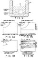
- Fig. 5A is a sectional view showing a crucible for melting active metal main body 11 and water-cooled hearth 13
- Fig. 5B is a schematic diagram of fine texture of part A of Fig. 5A.
- the crucible main body 11 side is exposed to high temperature and is hence made of high melting metal W
- the water-cooled hearth 13 is made of Cu which is excellent in thermal conductivity
- the gradient composition region 14 of W and Cu is a so-called gradient composition varying continuously in composition.
- Numeral 12 is a water cooling hole.
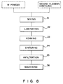
- the process is as shown in Fig. 6. That is, at the first step 21, W fine powder is prepared, and it is laminated in the shape of the crucible main body 11 in Fig. 5.
- the laminate obtained in the first step 21 is formed, for example, by CIP (cold isostatic pressing) to produce a W form.
- the W form obtained in the second step 22 is held in H 2 or other reducing high-temperature atmosphere for about several hours to produce a W sinter.
- the sintered W body obtained in the third step 23 is machined to finally finish into a crucible shape. In this case, it is machined including the gradient portion of the interface.
- the density becomes 95% or more at the inside of the crucible main body 11.
- the manufacturing conditions such as material powder, forming pressure, sintering temperature and others are controlled so that the density may change continuously to about 50% at the outside of the crucible main body 11.
- the fifth step 25 Cu is melted by some means, and the sintered W obtained in the third process 23 is infiltrated into this molten bath of W, and after holding until the molten Cu is sufficiently penetrating into the pores of the sintered W, it is cooled.
- the fifth process 25 is conducted in reducing high temperature atmosphere of H 2 or the like, and in the sixth process 26, after sufficiently cooling, it is taken out into the atmosphere, and is machined to the specified dimensions of the crucible main body 11 and water-cooled hearth 13.
- the crucible made of such composite metal material manufactured in such fabricating method (Fig. 5) is wide in the contact area of the gradient composition region 14 with W and Cu, and hence the adhesion and thermal conductivity are excellent. Moreover, since the composition of the gradient composition region 14 is gradient, it is effective to reduce the peak value of the thermal stress caused when heating due to the difference in the coefficient of thermal expansion between W and Cu.
- the crucible of the embodiment is characteristic in that a sintered W crucible continuously varying in the porosity at the outside of the crucible main body 11 is fabricated.
- the effect of the material powder on the density of sintered body as shown in Fig. 7 by varying the powder particle size within a range of 1 ⁇ m to 10 ⁇ m, it is possible to fabricate a W sinter possessing the relative density of 60% to 95%.
- the sintered W crucible varying continuously in density from 95% to 60% can be manufactured.
- the effect is not so great as to change the powder particle size, it is also a method to vary the forming pressure and sintering temperature for changing the density of the sinter, and by combining them, it is possible to fabricate the sintered W crucible main body 11 more effectively.
- the molten Cu is very likely on a solid W to wet, and it penetrates into the closed pores in the sintered W body. Since the boundary of the closed pores and open pores of the sintered W body is about 90%, the majority is infiltrated into the low density area of the outside of the sintered W crucible main body 11. Therefore, since the density of the outside of the sintered W crucible main body 11 changes continuously, a crucible of gradient composition of W and Cu is completed in this way.
- the interface composition of W and Cu is gradient, and the contact area of W and Cu is increased, so that the following effects are brought about.
- the second embodiment relates to an active metal melting crucible or heat receiving plate, but it may be also applied in other high temperature devices that require the combination of W and Cu.
- the combination of W and Cu is presented, but it is not limitative, and it may be applied to any other two materials as far as they differ in melting point and are not mutually miscible in solid solution.
- the mechanical strength is not fully satisfactory because it requires a step of manufacturing a sintered W body having a porosity distribution in the plate thicknesswise direction, and a step of sintering and infiltrating of molten Cu into pores of the sintered W body. That is, since the W which is responsible for mechanical strength undergoes a step of sintering, the grain boundary is particularly weak in the recrystallized grains.
- this sintered W body is required to have a porosity distribution in the plate thicknesswise direction, hot forging cannot be applied as the post-processing for enhancing the mechanical strength. Therefore, even if the thermal stress is alleviated by sloping the composition at the interface of W and Cu, since the mechanical strength is low, cracks may be formed in the W.
- the solid solution composition in order to enhance the mechanical strength of the first embodiment, in a combination of two materials of single composition such as W/Cu gradient material, by adding a second element which is miscible in solid solution, for example, powder of Re (rhenium), Ta (tantalum), Nb (niobium) or Hf (hafnium), the solid solution composition is sloped, so that only the mechanical strength is enhanced while holding the same functions.
- a second element which is miscible in solid solution for example, powder of Re (rhenium), Ta (tantalum), Nb (niobium) or Hf (hafnium
- Re powder is added to the W powder differing in particle size.
- the laminate laminated in the second step 32 is formed by die press forming or CIP forming method.
- the form obtained in the third step 33 is sintered, and the solid-solution element is alloyed with W, thereby obtaining a W alloy sintered body having a porosity distribution in the plate thicknesswise direction (W-HIP material in Fig. 9).
- the W alloy sintered body obtained in the fourth step 34 is impregnated in molten Cu and Cu is infiltrated in pores, and it is cooled.
- the infiltrated material obtained in the fifth step 35 is machined and finished to a desired product shape.
- the fourth embodiment is, similar to the third embodiment, a fabricating method of composite material enhanced only in the mechanical strength, while maintaining the functions, in which, in order to enhance the mechanical strength of the first embodiment, in a combination of two materials of single composition such as W/Cu gradient material, a second element or compound not miscible in solid solution, such as ThO 2 (thoria) powder is added, and the dispersion is intensified to slope the composition.
- a second element or compound not miscible in solid solution such as ThO 2 (thoria) powder
- the four embodiment is same as the third embodiment except that, as shown in the process chart in Fig. 8, ThO 2 powder is added to the W powder differing in particle size in the first step 31.
- the materials obtained by the third and fourth embodiments feature the following points.
- ThO 2 is used as the dispersion reinforcing agent, but basically any other material may be used as far as it is stable chemically and high in melting point, and any of the dispersion reinforcing agents shown in Fig. 10, that is, TaB 2 , TiB 2 , HfB 2 , Y 2 O 3 , ZrO 2 , may be used.
- peeling at the interface of W and Cu and cracks in material may be eliminated, and finally rise of material temperature and melting accident derived from the increase of thermal stress due to peeling or cracking may be eradicated.
- Fig. 11A, Fig. 11B relate to an example of application of the composite material obtained in the third embodiment in the beam target for active metal melting crucible or the like, in which Fig. 11A is a schematic diagram of a target for electron beam (EB), and Fig. 11B is a sectional view showing the section cut in the direction of the arrow along the line A-A in Fig. 11A. Since the C side of the beam target 121 is exposed to the EB 116 and high in temperature, it is made of W alloy of high melting point and high strength.
- EB target for electron beam
- the D side on the opposite side of the beam target 121 is made of Cu which is excellent in thermal conductivity and machinability, and it is cooled in water with water cooling pipe 117. Between the C side and D side, the composition ratio of W alloy and Cu changes continuously, that is, the so-called gradient composition is made.
- the composite material used in Fig. 11A, Fig. 11B is manufactured in the following procedure.
- the W alloy sintered body 118 is fabricated same as shown in Fig. 8, from the first to the fourth steps.
- the low porosity side is set at the upper side, and the build-up part of Cu is disposed at the opposite side.
- the water-cooling pipe 117 is brazed by using Ag-Cu solder or the like, thereby completing the beam target 121.
- the W alloy and Cu are in gradient composition, and the Cu of excellent thermal conductivity is in network structure, and therefore the temperature reached during use may be lowered, and the thermal stress may be alleviated.
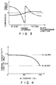
- Fig. 13 shows the result of analysis of temperature distribution and thermal stress (principal stress) distribution when the electron beam target shown in Fig. 11 is exposed to electron beam.
- Fig. 13A and Fig. 13C are to compare the result of analysis by finite element method of temperature distribution when heated by linear EB of 5 kW/cm 2 each, between the W alloy/Cu gradient material, and W alloy/Cu brazed material.
- Fig. 13B and Fig. 13D are to compare the thermal tress distribution when heated by linear EB of 5 kW/cm 2 each by the same finite element method, between the W alloy/Cu gradient material and W alloy/Cu brazed material. It is known from the result that the maximum reaching temperature may be lowered by about 80 K by composing gradient material. Besides immediately, beneath the EB where the temperature gradient is the greatest, the maximum thermal stress is known to be reduced to about 1/3.
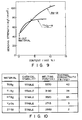
- Fig. 14 shows the EB input heat density, generated maximum thermal stress, and maximum reaching temperature as analyzed by finite element method.
- the maximum thermal stress is generated in the W alloy layer immediately beneath the heat source, and since the degree of lowering of strength of each part does not seem to be so great owing to compounding with Cu, the breakdown of beam target 121 is considered to be induced when the stress generated in the alloy layer becomes larger than its strength.
- Figs. 13A to 13D are central lines of distribution diagrams. Only right half of each distribution diagram is, hence, illustrated, since the left half if symmetrical to the right half.
- the strength is about 0.4 GPa, and the maximum applicable input heat density is about 4 kW/cm 2 at most, but in the case of W-5Re alloy adding 5% Re, the strength is increased about twice to 0.8 GPa, so that an EB input of about 8 kW/cm 2 is possible.
- the input heat density is 9 kW/cm 2 the maximum reaching temperature exceeds the melting point of W alloy, and it is meaningless if the Re content is increased to raise the strength, which is the application limit for the beam target 121.
- the beam target 121 especially linear EB heating, is mentioned, but it may be also applied to all other high temperature equipment parts requiring heat resistance and thermal conductivity, and the beam form is not limited to EB, but it may be applied to all heat sources.
- a fifth embodiment is described below by reference to Figs. 15, 16.
- the fabricating method of the fifth embodiment comprises the first step 41 through fourth step 44.
- a high strength substrate 45 is prepared by rolling, forging or other plastic processing.
- the high strength substrate 45 fabricated in the first step 41 is sprayed by a known vacuum plasma spraying apparatus as mentioned below, On the heating surface in the case of EB irradiated beam target, or a material producing a large stress locally, and the sprayed film with gradient porosity is made of two materials.
- the material obtained in the second step 42 is applied to a capsule-free HIP (hot isostatic pressing) device to remove the closed pores (defects) which may initiate breakdown.
- a composite material having a gradient composition layer 46 is completed as shown in Fig. 16.
- VPS vacuum plasma spraying
- the capsule-free HIP (open HIP) is a process of conducting hot isostatic pressing on the material not contained in a capsule, and is different from the ordinary HIP in which no pressure is applied to the inner part of the material which is contained in a capsule which collapses at high temperatures.
- the porosity by spraying method depends greatly on the particle size of the powder to be used, in other words, a spray film with gradient porosity is formed only by varying the particle size of the powder to be used.
- the vacuum plasma spraying method is to spray in a reduced inert atmosphere of about tens to hundreds of Torr, it is possible to form a film less in oxide coating, strong in bonding force among particles, and tight in contact with the high strength substrate.
- a capsule-free HIP it is possible to eliminate causes of increase of thermal resistance, or closed pores where stress is concentrated. In this case, by performing infiltration at ordinary pressure or high pressure with inert gas or in reducing atmosphere, the open pores may be filled up with the second material.
- cracks and other defects in electron beam heating may be reduced, while the input heat density may be increased.
- this method comprises the first step 51 through the fifth step 55.
- substrate surface is cleaned at the first step.
- the substrate cleaned in the first step 51 and the same material are sprayed, for example by vacuum plasma spraying, to slope the composition continuously.
- the third step 53 by the open HIP, leaving the open pores (communicating with outside) formed in the second step 52, the closed pores (not communicating with outside) are destroyed.
- a low melting metal for example, Cu is infiltrated into the pores obtained in the third step 53.
- the fifth step 55 is for machining.
- the sixth embodiment brings about the following effects. Since the vacuum plasma spraying in the second step 52 is to spray in an inert gas atmosphere at tens of Torr, the material is not oxidized. By using powder material of large particle size for spraying, the internal unmolten particles drift and deposit, and a film of a relatively large porosity may be formed.
- the closed pores can be eliminated while leaving the open pores formed by vacuum plasma spraying in the second step 52.
- the low melting material Cu By infiltrating the low melting material Cu into the material W possessing only open pores and having gradient pores obtained in this way, it is possible to spray in a relatively wide area, and a large and continuous gradient material may be fabricated.
- a gradient structure may be formed, and the gradient is continuous, while it was stepwise in the first embodiment, so that the thermal stress may be alleviated furthermore. Consequently, the thermal stress alleviation on the interface of different materials such as coating and joint may function effectively, so that the heat cycle characteristic and heat resistance may be improved.
- any one of W, Mo, Ta, Nb, Re, V, ZrO 2 , MgO, Al 2 O 3 , Y 2 O 3 , SiC, Si 3 N 4 , BN, AlN may be used, and the low melting material may be selected from Cu, Ag, Fe, Ni, Co or their alloys.
- the vacuum plasma spraying in the sixth embodiment is not limitative, but as far as the material is excellent in oxidation resistance, any atmospheric spraying method such as plasma spraying, gas spraying and arc spraying method may be applied, and same effects will be obtained.
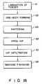
- a seventh embodiment is explained by reference to the process chart in Fig. 18.
- This embodiment is characterized by the HIP infiltration to treat at high pressure, when infiltrating the second material into the pores of the first material in the fourth step of the first embodiment. That is, after obtaining the sintered body in the third step 63, infiltration by open HIP is conducted at the fourth step 64, and then HIP infiltration is carried out at the fifth step 65.
- the second material can be securely infiltrated into open pores.
- inert gas such as Ar and He
- the problem of oxidation of material may be eliminated.
- an active element may be added in the liquid to promote infiltration into the fine pores.
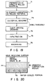
- FIG. 19 is a process chart for explaining the fabricating method, and at the first step 71, the dope rolled material is fabricated to make the heat receiving side with single crystals of W, Mo. At the step 72, the surface of the rolled material obtained in the first step 71 is roughened by blasting or the like, and W powder is laminated in gradient.
- the materials are sent to the fourth step 74, in which, simultaneously with the third step 73, by making use of secondary recrystallization, the minimum surface doped W, Mo rolled materials of W, Mo are grown into giant crystal grains to prepare a skeleton of W or Mo.
- the heat receiving side is the single crystal.
- Cu is infiltrated into the pores sloped at the fourth step 74, and it is machined and finished at the sixth step 76.
- the heat receiving material 77 made in such process is shown in Fig. 20.
- the large thermal stress receiving unstationarily is borne by the single crystal W Or Mo excelling in ductility on the heat receiving surface 78, while the stationary thermal stress is alleviated by the W/Cu gradient composition beneath it.
- the W/Cu gradient composition beneath it By eliminating the grain boundary of W and Mo where grain boundary brittleness is likely to occur, a heat receiving material having W, Mo extremely excellent in ductility disposed at the heating side is obtained. Aside from superior heating performance, the thermal impact property by quick heating is improved.
- This embodiment for manufacturing the heat receiving material also avoids the following points. That is, in fabrication of sintered body of W, Mo and giant crystal grain growth, sintering of W, Mo powder is sometimes promoted too much, and a porosity gradient region may not be fabricated sufficiently. Accordingly, in this embodiment, by using particles of about 10 microns, this problem is avoided. Besides, by vacuum plasma spraying, it is possible to form a gradient region 80 of W, Mo on the rear side of the single crystal plate. Moreover, by executing the giant crystal growth in the first place, the powder may be laminated in gradient on the surface of the single crystal material, and then the sintered bond Cu is infiltrated, so that a similar heat receiving plate may be manufactured.
- the heat receiving side 78 is W, or Mo, but this heat receiving side may be also made of Re or V, or an alloy mainly comprising W, Mo, Re or V.
- a high thermal conductive material such as Cu, Ag, Fe or their alloy may be formed, and the composition may be sloped from the heat receiving side 78 to the opposite side.
Landscapes
- Chemical & Material Sciences (AREA)
- Engineering & Computer Science (AREA)
- Mechanical Engineering (AREA)
- Materials Engineering (AREA)
- Metallurgy (AREA)
- Organic Chemistry (AREA)
- Physics & Mathematics (AREA)
- Plasma & Fusion (AREA)
- Chemical Kinetics & Catalysis (AREA)
- General Engineering & Computer Science (AREA)
- Thermal Sciences (AREA)
- Manufacturing & Machinery (AREA)
- Powder Metallurgy (AREA)
- Coating By Spraying Or Casting (AREA)
Claims (11)
- Verfahren zur Herstellung eines Kompositwerkstoffs aus einem ersten Material und einem zweiten Material, die sich miteinander in fester Lösung nicht mischen und einen relativ hohen bzw. relativ niedrigen Schmelzpunkt aufweisen,durch Ausbilden von Poren in dem ersten Material in einer ersten Stufe zur Gewinnung eines Substratmaterials mit Porositätsverteilung, wobei die Porosität schrittweise von einem in dem ersten Material festgelegten Oberflächenbereich in Richtung auf einen zweiten Bereich abnimmt, unter Anwendung einer oder mehrerer Methode(n), ausgewählt aus der Gruppe thermische Spritzmethode, chemische Abscheidungsmethode und physikalische Abscheidungsmethode, undInfiltrieren des zweiten Materials in aufgeschmolzenem Zustand in die Poren des in der ersten Stufe erhaltenen ersten Materials mit der Porositätsverteilung, bei der die Porosität schrittweise abnimmt, in einer zweiten Stufe zur Gewinnung eines Werkstoffs mit Zusammensetzungsgradienten einer Gradientenverteilung des Kompositverhältnisses erstes Material und zweites Material.
- Herstellungsverfahren nach Anspruch 1, wobei die erste Stufe zur Gewinnung des die Porositätsverteilung aufweisenden Substratmaterials mit schrittweise abnehmender Porosität folgende Unterstufen umfaßt:(a) Ausformen eines Gemischs aus dem ersten Material und einem mit dem ersten Material mischbaren Element im Zustand einer festen Lösung während des Ausformens zur Bildung eines Formlings und(b) Sintern des in der Unterstufe (a) erhaltenen Formlings zur Verstärkung der festen Lösung unter Gewinnung des Substratmaterials mit Porositätsverteilung, bei der die Porosität schrittweise abnimmt.
- Herstellungsverfahren nach Anspruch 1, wobei die erste Stufe zur Gewinnung des die Porositätsverteilung aufweisenden Substratmaterials mit schrittweise abnehmender Porosität folgende Unterstufen umfaßt:(c) Ausformen eines Gemischs des ersten Materials und eines aus der Gruppe Mehrzahl von Arten von Verbindungsmaterialien mit der Eigenschaft, ohne mit dem ersten Material während der Formgebung chemisch zu reagieren, dispergiert zu werden, ausgewählten Materials zur Gewinnung eines Formlings und(d) Sintern des in der Unterstufe (c) erhaltenen Formlings zur Dispersionsverstärkung unter Gewinnung des Substratmaterials mit Porositätsverteilung, bei der die Porosität schrittweise abnimmt.
- Herstellungsverfahren nach Anspruch 1, wobei die erste Stufe umfaßt:(e) Herstellen eines verstärkten Teils durch Verstärken des ersten Materials nach einer Methode, ausgewählt aus der Gruppe Walzen, Schmieden und Legieren, und(f) Aufsprühen eines gemeinsamen Materials auf das erhaltene verstärkte Teil durch Vakuumplasmaspritzmaßnahmen zur Gewinnung eines Substratmaterials mit Porositätsverteilung.
- Herstellungsverfahren nach Anspruch 4, wobei die erste Stufe der Porenbildung durch Aufsprühen eines dem verstärkten Teil ähnlichen Materials durch Spritzmaßnahmen ausgeführt werden kann.
- Herstellungsverfahren nach Anspruch 4, wobei die erste Stufe folgende Unterstufen umfaßt:(g) Behandeln des in der ersten Stufe erhaltenen verstärkten Teils durch Aufsprühen eines dem verstärkten Teil ähnlichen Materials mit Hilfe von Spritzmaßnahmen zur Herstellung des porenhaltigen Substratmaterials und(h) Behandeln des in Unterstufe (g) erhaltenen Substratmaterials durch isotaktisches Heißpressen.
- Herstellungsverfahren nach Anspruch 6, wobei die isotaktische Heißpreßbehandlung nach einem kapselfreien Verfahren, bei dem das Substrat ohne in eine Kapsel eingebracht zu werden, behandelt wird, erfolgt.
- Herstellungsverfahren nach Anspruch 1, wobei die erste Stufe folgende Stufen umfaßt:Ausbilden eines Laminats aus einem Substratmaterial, ausgewählt aus der Gruppe mit einem Dopemittel versetztes, preßgewalztes Material und geschmiedetes Material als schwach wärmeleitender Werkstoff, und einem Pulver derselben Art wie das Substratmaterial, wobei das Pulver auf einer Seite des gewählten Substratmaterials angehäuft ist, undHerstellen eines Sintermaterials mit Porositätsverteilung durch Sintern des Laminats.
- Herstellungsverfahren nach Anspruch 8, wobei eine Seite des gewählten Substratmaterials durch Vakuumplasmaspritzen mit dem Pulver bedeckt wird.
- Herstellungsverfahren nach Anspruch 1, wobei die erste Stufe folgende Unterstufen umfaßt:Zubereiten einer Mehrzahl von Gemischen unterschiedlicher Korngröße durch Mischen eines pulverförmigen ersten Materials unterschiedlicher Korngröße mit einem zweiten pulverförmigen Element, das mit dem ersten pulverförmigen Material in fester Lösung löslich ist,Ausbilden eines Laminatteils, bei dem die in der ersten Unterstufe gebildeten Mischungen derart aufeinandergestapelt sind, daß die Korngröße der Mischungen vom Boden des Laminatteils zu seiner Oberseite hin zunimmt,Ausbilden eines in fester Lösung verstärkten Teils durch Behandeln des in der zweiten Unterstufe erhaltenen Laminatteils, undHerstellen eines gesinterten Teils durch Sintern des in der dritten Unterstufe gebildeten Laminatteils dergestalt, daß das gesinterte Teil eine poröse Verteilung erhält.
- Herstellungsverfahren nach Anspruch 1, wobei die erste Stufe folgende Unterstufen umfaßt:Zubereiten einer Mehrzahl von Gemischen unterschiedlicher Korngröße durch Mischen eines pulverförmigen ersten Materials unterschiedlicher Korngröße mit einem zweiten pulverförmigen Element, das mit dem ersten pulverförmigen Material in fester Lösung löslich ist,Ausbilden eines Laminatteils, bei dem die in der ersten Unterstufe gebildeten Gemische derart aufeinandergestapelt sind, daß die Korngröße der Gemische vom Boden des Laminatteils zu seiner Oberseite hin zunimmt,Ausbilden eines dispergierten und verstärkten Teils durch Behandeln des in der zweiten Unterstufe gebildeten Laminatteils undHerstellen eines gesinterten porösen Teils durch Sintern des in der dritten Unterstufe gebildeten Laminatteils dergestalt, daß das gesinterte Teil eine Porositätsverteilung erhält.
Applications Claiming Priority (4)
| Application Number | Priority Date | Filing Date | Title |
|---|---|---|---|
| JP6519790 | 1990-03-15 | ||
| JP65197/90 | 1990-03-15 | ||
| JP59545/91 | 1991-02-28 | ||
| JP3059545A JP2950436B2 (ja) | 1990-03-15 | 1991-02-28 | 複合化材料の製造方法 |
Publications (3)
| Publication Number | Publication Date |
|---|---|
| EP0446934A2 EP0446934A2 (de) | 1991-09-18 |
| EP0446934A3 EP0446934A3 (en) | 1993-06-30 |
| EP0446934B1 true EP0446934B1 (de) | 1998-09-23 |
Family
ID=26400588
Family Applications (1)
| Application Number | Title | Priority Date | Filing Date |
|---|---|---|---|
| EP91103974A Expired - Lifetime EP0446934B1 (de) | 1990-03-15 | 1991-03-14 | Verfahren zur Herstellung von Kompositmaterial |
Country Status (4)
| Country | Link |
|---|---|
| EP (1) | EP0446934B1 (de) |
| JP (1) | JP2950436B2 (de) |
| KR (1) | KR940008937B1 (de) |
| DE (1) | DE69130237T2 (de) |
Families Citing this family (13)
| Publication number | Priority date | Publication date | Assignee | Title |
|---|---|---|---|---|
| US5204055A (en) * | 1989-12-08 | 1993-04-20 | Massachusetts Institute Of Technology | Three-dimensional printing techniques |
| US5814161A (en) * | 1992-11-30 | 1998-09-29 | Massachusetts Institute Of Technology | Ceramic mold finishing techniques for removing powder |
| US5775402A (en) * | 1995-10-31 | 1998-07-07 | Massachusetts Institute Of Technology | Enhancement of thermal properties of tooling made by solid free form fabrication techniques |
| US6146567A (en) * | 1993-02-18 | 2000-11-14 | Massachusetts Institute Of Technology | Three dimensional printing methods |
| GB2287038A (en) * | 1993-09-30 | 1995-09-06 | Automotive Products Plc | Metal matrix composites |
| GB9320150D0 (en) * | 1993-09-30 | 1993-11-17 | Automotive Products Plc | Metal matrix composite components |
| US5660621A (en) * | 1995-12-29 | 1997-08-26 | Massachusetts Institute Of Technology | Binder composition for use in three dimensional printing |
| RU2167741C2 (ru) * | 1999-06-08 | 2001-05-27 | Южно-Российский государственный технический университет | Способ изготовления низкопористых порошковых материалов |
| DE10301175B4 (de) * | 2003-01-08 | 2006-12-07 | Fraunhofer-Gesellschaft zur Förderung der angewandten Forschung e.V. | Verfahren zur pulvermetallurgischen Herstellung von Bauteilen |
| AT13536U1 (de) * | 2013-05-07 | 2014-02-15 | Plansee Se | Verfahren zur Herstellung eines Formkörpers und damit herstellbarer Formkörper |
| DE102015207602A1 (de) * | 2015-04-24 | 2016-10-27 | Gfe Metalle Und Materialien Gmbh | Verfahren zur Herstellung einer Rohrkathode zum Einsatz in PVD-ARC-Beschichtungsanlagen |
| JP6366643B2 (ja) * | 2016-06-20 | 2018-08-01 | 新日鉄住金マテリアルズ株式会社 | 溶射膜を有する基材の製造方法 |
| CN115923262A (zh) * | 2022-11-30 | 2023-04-07 | 青海大学 | 一种采用粉末夹层法制备W和Al多层复合板材的方法 |
Family Cites Families (7)
| Publication number | Priority date | Publication date | Assignee | Title |
|---|---|---|---|---|
| US3929424A (en) * | 1973-10-23 | 1975-12-30 | Mallory & Co Inc P R | Infiltration of refractory metal base materials |
| US3960554A (en) * | 1974-06-03 | 1976-06-01 | Westinghouse Electric Corporation | Powdered metallurgical process for forming vacuum interrupter contacts |
| US4718941A (en) * | 1986-06-17 | 1988-01-12 | The Regents Of The University Of California | Infiltration processing of boron carbide-, boron-, and boride-reactive metal cermets |
| DE3627775A1 (de) * | 1986-08-16 | 1988-02-18 | Demetron | Verfahren zur herstellung von targets |
| DE3724995A1 (de) * | 1987-02-26 | 1988-09-08 | Radex Heraklith | Verfahren zur herstellung eines verbundkoerpers und verbundkoerper selbst |
| US4917722A (en) * | 1988-05-18 | 1990-04-17 | Tosoh Corporation | Single crystals of chromium and method for producing the same |
| DE3907625C1 (de) * | 1989-03-09 | 1990-02-15 | Mtu Muenchen Gmbh |
-
1991
- 1991-02-28 JP JP3059545A patent/JP2950436B2/ja not_active Expired - Fee Related
- 1991-03-14 EP EP91103974A patent/EP0446934B1/de not_active Expired - Lifetime
- 1991-03-14 DE DE69130237T patent/DE69130237T2/de not_active Expired - Fee Related
- 1991-03-15 KR KR1019910004112A patent/KR940008937B1/ko not_active Expired - Fee Related
Also Published As
| Publication number | Publication date |
|---|---|
| JPH04214826A (ja) | 1992-08-05 |
| EP0446934A2 (de) | 1991-09-18 |
| EP0446934A3 (en) | 1993-06-30 |
| DE69130237T2 (de) | 1999-03-25 |
| DE69130237D1 (de) | 1998-10-29 |
| KR940008937B1 (ko) | 1994-09-28 |
| JP2950436B2 (ja) | 1999-09-20 |
| KR910016950A (ko) | 1991-11-05 |
Similar Documents
| Publication | Publication Date | Title |
|---|---|---|
| US5126102A (en) | Fabricating method of composite material | |
| EP0446934B1 (de) | Verfahren zur Herstellung von Kompositmaterial | |
| US5130209A (en) | Arc sprayed continuously reinforced aluminum base composites and method | |
| US6037066A (en) | Functionally gradient material and method for producing the same | |
| CA2462491C (en) | Laminated component for fusion reactors | |
| US20090252984A1 (en) | Biaxially textured composite article | |
| EP1678733B1 (de) | Verfahren zur herstellung eines verbundkörpers durch hochtemperaturlöten einer nichtmetallischen komponente mit einer metallischen oder nichtmetallischen komponente | |
| JP7018603B2 (ja) | クラッド層の製造方法 | |
| US5963773A (en) | Tungsten skeleton structure fabrication method employed in application of copper infiltration and tungsten-copper composite material fabrication method thereof | |
| Sampath et al. | Plasma spray forming metals, intermetallics, and composites | |
| IE902034L (en) | Dimensionally reproducible compacts | |
| JP4051141B2 (ja) | タングステン,タングステン繊維強化複合材料およびモリブデン,モリブデン繊維強化複合材料およびその製造方法ならびに同材料を用いた高温部品 | |
| KR101200578B1 (ko) | 복합 소재 | |
| US5229165A (en) | Plasma sprayed continuously reinforced aluminum base composites | |
| US5217815A (en) | Arc sprayed continously reinforced aluminum base composites | |
| US5141145A (en) | Arc sprayed continuously reinforced aluminum base composites | |
| JPH05186276A (ja) | カーボンファイバ強化カーボン複合材を用いた受熱板材料およびその製造方法 | |
| JP2008169463A (ja) | コバルト−タングステン・スパッタターゲット及びその製造方法 | |
| WO2008124436A1 (en) | Composite substrates for high temperature superconductors having improved properties | |
| Dahotre et al. | Laser induced liquid phase reaction synthesis assisted joining of metal matrix composites | |
| Li et al. | Joining reaction-bonded silicon carbide using Inconel 600 superalloy. | |
| JPH07232261A (ja) | 複合金属材料とその製造方法、およびそれを用いた電磁調理器用容器 | |
| Binczyk et al. | Intermetallic Fe-Al layers obtained by the powder cloth method | |
| KR20190050561A (ko) | 알루미늄-티타늄 이종 경사기능복합재료 및 이의 제조방법 | |
| JPH07258816A (ja) | 金属基材へのセラミックコーティング構造およびその形成方法 |
Legal Events
| Date | Code | Title | Description |
|---|---|---|---|
| PUAI | Public reference made under article 153(3) epc to a published international application that has entered the european phase |
Free format text: ORIGINAL CODE: 0009012 |
|
| 17P | Request for examination filed |
Effective date: 19910411 |
|
| AK | Designated contracting states |
Kind code of ref document: A2 Designated state(s): DE FR GB |
|
| PUAL | Search report despatched |
Free format text: ORIGINAL CODE: 0009013 |
|
| AK | Designated contracting states |
Kind code of ref document: A3 Designated state(s): DE FR GB |
|
| 17Q | First examination report despatched |
Effective date: 19950302 |
|
| GRAG | Despatch of communication of intention to grant |
Free format text: ORIGINAL CODE: EPIDOS AGRA |
|
| GRAG | Despatch of communication of intention to grant |
Free format text: ORIGINAL CODE: EPIDOS AGRA |
|
| GRAH | Despatch of communication of intention to grant a patent |
Free format text: ORIGINAL CODE: EPIDOS IGRA |
|
| GRAH | Despatch of communication of intention to grant a patent |
Free format text: ORIGINAL CODE: EPIDOS IGRA |
|
| GRAA | (expected) grant |
Free format text: ORIGINAL CODE: 0009210 |
|
| AK | Designated contracting states |
Kind code of ref document: B1 Designated state(s): DE FR GB |
|
| REF | Corresponds to: |
Ref document number: 69130237 Country of ref document: DE Date of ref document: 19981029 |
|
| ET | Fr: translation filed | ||
| PLBE | No opposition filed within time limit |
Free format text: ORIGINAL CODE: 0009261 |
|
| STAA | Information on the status of an ep patent application or granted ep patent |
Free format text: STATUS: NO OPPOSITION FILED WITHIN TIME LIMIT |
|
| 26N | No opposition filed | ||
| REG | Reference to a national code |
Ref country code: GB Ref legal event code: IF02 |
|
| PGFP | Annual fee paid to national office [announced via postgrant information from national office to epo] |
Ref country code: GB Payment date: 20020313 Year of fee payment: 12 |
|
| PG25 | Lapsed in a contracting state [announced via postgrant information from national office to epo] |
Ref country code: GB Free format text: LAPSE BECAUSE OF NON-PAYMENT OF DUE FEES Effective date: 20030314 |
|
| GBPC | Gb: european patent ceased through non-payment of renewal fee |
Effective date: 20030314 |
|
| PGFP | Annual fee paid to national office [announced via postgrant information from national office to epo] |
Ref country code: DE Payment date: 20080306 Year of fee payment: 18 Ref country code: FR Payment date: 20080311 Year of fee payment: 18 |
|
| REG | Reference to a national code |
Ref country code: FR Ref legal event code: ST Effective date: 20091130 |
|
| PG25 | Lapsed in a contracting state [announced via postgrant information from national office to epo] |
Ref country code: DE Free format text: LAPSE BECAUSE OF NON-PAYMENT OF DUE FEES Effective date: 20091001 |
|
| PG25 | Lapsed in a contracting state [announced via postgrant information from national office to epo] |
Ref country code: FR Free format text: LAPSE BECAUSE OF NON-PAYMENT OF DUE FEES Effective date: 20091123 |