EP0446902B1 - Gerät zum automatischen Fahren - Google Patents
Gerät zum automatischen Fahren Download PDFInfo
- Publication number
- EP0446902B1 EP0446902B1 EP91103852A EP91103852A EP0446902B1 EP 0446902 B1 EP0446902 B1 EP 0446902B1 EP 91103852 A EP91103852 A EP 91103852A EP 91103852 A EP91103852 A EP 91103852A EP 0446902 B1 EP0446902 B1 EP 0446902B1
- Authority
- EP
- European Patent Office
- Prior art keywords
- vehicle
- target course
- image
- steering
- course
- Prior art date
- Legal status (The legal status is an assumption and is not a legal conclusion. Google has not performed a legal analysis and makes no representation as to the accuracy of the status listed.)
- Expired - Lifetime
Links
- 238000012545 processing Methods 0.000 claims description 26
- 238000005070 sampling Methods 0.000 claims description 19
- 230000008859 change Effects 0.000 claims description 4
- 238000006243 chemical reaction Methods 0.000 description 6
- 230000009466 transformation Effects 0.000 description 6
- 230000000007 visual effect Effects 0.000 description 3
- 230000007423 decrease Effects 0.000 description 2
- 230000004069 differentiation Effects 0.000 description 2
- 230000009471 action Effects 0.000 description 1
- 238000013459 approach Methods 0.000 description 1
- 230000008901 benefit Effects 0.000 description 1
- 238000001514 detection method Methods 0.000 description 1
- 238000010586 diagram Methods 0.000 description 1
- 238000006073 displacement reaction Methods 0.000 description 1
- 238000000605 extraction Methods 0.000 description 1
- 230000015654 memory Effects 0.000 description 1
- 238000000034 method Methods 0.000 description 1
- 230000008569 process Effects 0.000 description 1
- 230000004044 response Effects 0.000 description 1
Images


Classifications
-
- G—PHYSICS
- G05—CONTROLLING; REGULATING
- G05D—SYSTEMS FOR CONTROLLING OR REGULATING NON-ELECTRIC VARIABLES
- G05D1/00—Control of position, course, altitude or attitude of land, water, air or space vehicles, e.g. using automatic pilots
- G05D1/02—Control of position or course in two dimensions
- G05D1/021—Control of position or course in two dimensions specially adapted to land vehicles
- G05D1/0212—Control of position or course in two dimensions specially adapted to land vehicles with means for defining a desired trajectory
-
- G—PHYSICS
- G05—CONTROLLING; REGULATING
- G05D—SYSTEMS FOR CONTROLLING OR REGULATING NON-ELECTRIC VARIABLES
- G05D1/00—Control of position, course, altitude or attitude of land, water, air or space vehicles, e.g. using automatic pilots
- G05D1/02—Control of position or course in two dimensions
- G05D1/021—Control of position or course in two dimensions specially adapted to land vehicles
- G05D1/0231—Control of position or course in two dimensions specially adapted to land vehicles using optical position detecting means
- G05D1/0246—Control of position or course in two dimensions specially adapted to land vehicles using optical position detecting means using a video camera in combination with image processing means
Definitions
- the present invention relates to an automatic travelling apparatus according to the preamble part of Claim 1.
- Such an automatic travelling apparatus is eg. known from the EP-A-0 354 361.
- the known apparatus is intended to continuously take an image of an area ahead of a vehicle in its running direction by an image pick-up device attached to the vehicle; make sampling of the image thus taken and data processing for extracting therefrom continuous line segments such as road edges; determine a a permissible travelling area ahead of the vehicle on the basis of the extracted continuous line segments; set a target course in the determined permissible travelling area; estimate a steering amount necessary for following the target course on the basis of the currently detected running condition of the vehicle; and steer the vehicle to follow the target course with reference to the steering amount.
- the steering control may be more accurate as the sampling period i.e., steering control cycle is shorter.
- the time required for processing each image and finally determining a permissible travelling area is fairly longer in comparison with the processing time for steering vehicle to follow the target course set in the permissible travelling area.
- the image processing time is 500 milliseconds whereas the processing time for steering control is 10 milliseconds.
- the vehicle may travel enough to produce a deviation of its actual position with respect to the determined permissible travelling area, i.e., higher running speed brings larger deviation, causing a considerable decrease in accuracy of the steering control.
- an automatic travelling apparatus which corresponds, with respect to features of interest, essentially to the known automatic travelling apparatus corresponding to the preamble part of claim 1, discussed in the foregoing. From figure 10 of DE 38 20 589 A1, it may clearly be derived that there is only one control cycle for image processing (step 1001 of fig. 10) and steering control (steps 1004 and 1005), the steering amount therefore being estimated only once during each period of image sampling. Therefore, this automatic travelling apparatus has essentially the same drawbacks as the automatic travelling apparatus as discussed in the foregoing, i.e. that the accuracy of the steering control is limited because of the rather long image sampling period. For higher running speed this can result in larger deviations of the vehicle from the target course.
- the EP 0 273 976 A1 discloses an automatic travelling apparatus designed for following a fixed course.
- the apparatus determines its coordinate position and posture with respect to the fixed course by dead-reckoning (referred to as speculation navigation) and compares the "speculated" coordinate data with predetermined target coordinate data with respect to the fixed course. If the difference between the speculated coordinate data and the target coordinate data is higher than a respective threshold, the rotational speed of the driving wheels is altered according to a predetermined formula, whereby the rotational speed of one wheel increases by the amount ⁇ V, whereas the rotational speed of the other wheel decreases by the amount ⁇ V.
- This scheme of controlling a vehicle along a fixed course corresponds to a sort of closed-loop control.
- visual recognizing means comprising, for example, a TV-camera, are provided, which allow the estimation of the true coordinates on the basis of ground marks besides or on the fixed course of the vehicle.
- the coordinate data obtained by visual recognition serve for correcting the speculated coordinate data for directly correcting the position of the vehicle with respect to the fixed course.
- the position of the vehicle is corrected by the motors M R and M L correspondingly.
- a smooth overall course of the vehicle is not to be expected.
- the fixed target course is defined by a series of target displacement d i and target declination angles ⁇ i referring to positions P i , which apparently are the positions of respective ground marks, where the fixed target course changes with respect to a reference passage constituted by line sections connecting the ground marks.
- the duration of the image sampling period does not limit the accuracy of the steering control, since the steering amount is repeatedly newly estimated during a period of image sampling on the basis of the Instantaneous running condition and on the renewed vehicle position, permitting the vehicle to follow the target course smoothly and accurately. If necessary, for example in case of a deviation of the vehicle with respect to the target course, the target course is reset in the permissible travelling area instead of correcting the position and/or posture of the vehicle. This measure allows the vehicle to follow a smooth overall course in the permissible travelling area since the vehicle is not forced back on the old target course once having set in the permissible travelling area.
- Fig. 1 is a block diagram showing a structure of an automatic travelling apparatus embodying the present invention.
- Fig. 2 shows a line segment of a road obtained on the basis of processing an image taken by a video camera.
- Fig. 3 shows an image obtained by projective transformation of the image shown in Fig. 2.
- Fig. 4 shows an example of a target course set in a permissible area within a road width.
- Figs. 5 (a) and 5 (b) show target courses set on a road which a vehicle is to travel at a low speed (a) and a high speed (b) respectively.
- Fig. 6 shows a relationship between a target course and a presumed course.
- Fig. 7 shows a relationship between a vehicle's steering angle and its turning radius.
- Fig. 8 shows a travelling state of a vehicle in a permissible travelling area.
- Fig. 9 (a) shows a position and a running direction of a vehicle in a permissible travelling area at a certain time.
- Fig. 9 (b) shows a state obtained by coordinate transformation of a permissible travelling area in relation to a position and a running direction of a vehicle in a permissible travelling area.
- Fig. 10 shows a line segment in the X-Y coordinates.
- Fig. 11 shows a point on the ⁇ - ⁇ point coordinates obtained by the Hough conversion of the line segment shown in Fig. 10.
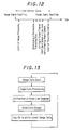
- Fig. 12 shows timings of processings in one control cycle.
- Fig. 13 shows a flow chart of image processing.
- Fig. 14 shows a flow chart of updating the vehicle position during image sampling.
- 1 is an image pick-up device, 2 an image processor, 3 a means for determining a permissible travelling area, 4 a means for setting a target course, 5 a controlling means, 6 a running speed sensor, 7 a Yaw rate sensor, 8 a steering angle sensor, 9 a steering controller, 10 a steering drive, 11 a vehicle.
- Characters RA, RA' denote permissible travelling areas and characters OC, OC' denote target courses.
- an automatic travelling apparatus comprises: an image pick-up device 1 such as a video camera attached to a vehicle for continuously picking up subsequent images of ground ahead of the vehicle; means 2 for processing the images taken by the image pick-up device 1 to extract therefrom segments of continuous lines such as road edges and the like; means 3 for determining, on the basis of the obtained continuous line segments, a permissible travelling area such as a road in the direction in which the vehicle is to travel; means 4 for setting a target course in the permissible travelling area thus determined; means 5 for determining the instantaneous running condition of the vehicle on the basis of an output signal from a speed sensor 6 representing the vehicle's running speed "v", an output signal from a jaw rate sensor 7 representing the yaw rate " ⁇ " and an output signal from a steering angle sensor 8 representing the tire angle " ⁇ " which varies with the steering of the vehicle, and for estimating, on the basis of the instantaneous running condition, a steering amount to permit the vehicle to follow the target
- microcomputer aided control is used in place of means 2, 3, 4 and 5, and means 9 can be included in the microcomputer aided control, if occasions demand.
- each image supplied from the image pick-up device 1 is subjected to differentiation process for detection of the road edges.
- an automatic threshold setting circuit in the image processing means 2 sets an optimum threshold value in consideration of the degree of shade of the road edge image information just processed.
- the road edge image will be subjected to binary transformation.
- the images may be subjected to binary transformation, and then the binary data may be subjected to differentiation.
- binary transformation poly-digitization may be performed to express some shade details of image.
- Digitalized image information will be subjected to the Hough conversion to convert the X-Y linear coordinates to the corresponding ⁇ - ⁇ point coordinates, thus eliminating isolated points and plotting to provide a continuous line segments of the road edges as shown in Fig. 2.
- ⁇ stands for an angle formed between the X-axis and a perpendicular from the origin of the X-Y coordinates to a line segment
- ⁇ stands for the length of the normal line.
- the line L in the X-Y coordinates in Fig. 10 is expressed as the point 01 in the ⁇ - ⁇ point coordinates in Fig. 11.
- edge tracing may be performed on the basis of binary-coded image information to obtain a continuous road edge.
- the Hough conversion, edge tracing and other appropriate processings may be performed simultaneously, and then synthetic judgement may be made on the results of these processings to obtain a precise road edge information. More accurate road edge information may be taken out when the above-mentioned image processings are made with developing an input image area as the vehicle travels.
- the image taken by a video camera represents a perspective view.
- the perspective road edge image as shown in Fig. 2 can be converted to non-perspective road edge image as shown in Fig. 3 according to the known projective conversion process.
- the permissible travelling area determining means 3 has a projective conversion characteristics set in consideration of the perspective characteristics of associated video cameras.
- the permissible travelling area determining means 3 can determine, on the basis of the non-perspective road image obtained by projective conversion, for instance, an area between the continuous road edges E1 and E2 shown in Fig. 4 as a permissible travelling area RA in the X-Y coordinates wherein the Y-axis corresponds to the direction in which the image is pictured by the image pick-up device 1, i.e., the vehicle travels.
- a current or instantaneous position of the vehicle 11 is indicated at a point "P"
- the video camera of the image pick-up device 1 is mounted at a predetermined position on the vehicle whereat the point "P" may appear at the center lower point of the display screen as the origin of the X-Y coordinates.
- the target course setting means 4 will select a course most appropriate for running in the permissible travelling area, and will set the so selected course as a target course to follow.
- the course may be determined in consideration of the road contour and the running speed of the vehicle to meet the instantaneous travelling condition of the vehicle.
- the course may be basically determined in the width of the road as follows:
- a target course OC will be set a given constant distance "w" (for instance, 1.5 meters) apart from the left edge of the road, as shown in Fig. 4.
- a target course will be set along the center line (not shown) of the road.
- the coordinates of the target course are stored in the memories of the target course setting means 4 and are continuously renewed as the vehicle is running.
- the divisions of the X-Y coordinates for the permissible travelling area and the target course are selected in compliance with the magnification of the video camera of the image pick-up device 1.
- the target course setting means 4 finds that the running speed measured by the speed sensor 6 is below a predetermined speed, the target course OC will be set in conformity with the road contour as seen from Fig. 4.
- a target course OC of reduced curvature is set so as to reduce the lateral force which is applied to the vehicle.
- control means 5 After setting a target course in the road, the control means 5 will estimate a steering amount to permit the vehicle to follow the target course as follows:
- the control means 5 When the steering amount relates to a steering angle of the vehicle, the control means 5 presumes a course which the vehicle will run along on the basis of the currently detected running condition; calculates a deviation of the presumed running course from the target course; determines an amount of steering angle to be corrected for bringing the vehicle to follow the target course; and then makes the steering control of the vehicle according to the steering amount, i.e., the steering angle for correction.
- the position whereto the vehicle will attain is presumed as a point on the X-Y coordinates having the Y-axis representing the running direction of the vehicle and the lateral deviation of the presumed point from the point of target position is measured to finally determine therefrom a corresponding amount of steering angle to be corrected.
- the positive sign of yaw rate ⁇ represents that the presumed course AC turns to the left whereas the negative sign indicates the presumed course turning to the right.
- the steering amount ⁇ ' for permitting the vehicle to get on the target course OC can be determined as follows:
- the steering control means 9 In response to the steering amount ⁇ ' given from the control means 5 the steering control means 9 issues a drive command to the steering drive 10 which in turn steers the vehicle toward the target course OC.
- the automatic travelling apparatus further includes means for renewing the vehicle position relative to the permissible travelling area currently fixed for a current control cycle on the basis of the instantaneous running condition of the vehicle, and means for resetting the target course for the renewed vehicle position in relation to the currently fixed permissible travelling area, and may determine a steering amount for permitting the vehicle to follow the the reset target course.
- control means 5 shown in Fig. 1.
- ⁇ L v ⁇ ⁇ t
- the target course for the renewed position Pn (Xn, Yn) of the vehicle is reset in respect to the permissible travelling area RA, a steering amount is also estimated with respect to the reset target course so as to steer the vehicle toward the target course.
- a new X'-Y' coordinate system in which the Y'-axis stands for the axis of running direction of the vehicle 11 at the renewed position Pn is formed, and then coordinate transformation of every points of the permissible travelling area RA' and the target course OC'is carried out in such a way that the renewed point Pn (Xn, Yn) in the X-Y coordinates may be placed to the origin Po' (X', Y').
- a steering amount for permitting the vehicle 11 to follow the target course OC' is determined with reference to the X'-Y' coordinates in the same manner as mentioned above, and the steering control will be performed with reference to said renewed steering amount.
- the steering amount for permitting the vehicle to follow the target course OC initially set in the permissible travelling area RA was estimated from the variable data as afore mentioned.
- the vehicle 11 in case of steering the vehicle 11 from the initial position Po with the initially estimated steering amount for a relatively long time of the control cycle the vehicle may progressively deviate from the target course OC due to the error included in the steering amount estimation.
- the present invention provides such a possibility that in one control cycle a target course OC' can be reset in a permissible travelling area RA' viewed from the vehicle's present position Pn to be successively renewed at intervals of relatively shorter period and be treated in preference to the preceding and, therefore, the steering control of the vehicle 11 can be carried out with a higher accuracy according to the steering amount newly estimated for the reset target course. Since the interval between renewals of the steering amount is relatively short, the error of estimation may have no practical influence to the steering control.
- the target course it is also possible to optimally change the target course with a change of the vehicle running speed in one control cycle in case the target course is set in a permissible travelling area depending on the vehicle's running speed as shown in Figs. 5(a) and 5(b).
- Fig. 12 is a timing chart showing each processing timing in one control cycle.
- Fig. 13 shows a flow of image processing
- Fig. 14 shows a flow of renewing the vehicle position during the image processing.
- the automatic travelling apparatus offers such an advantage that in each steering control cycle comprising steps - sampling an image of an area ahead of a running vehicle (said image being taken by the image pick-up means attached to the vehicle); processing sampled data and extracting therefrom continuous line segments; determining a permissible travelling area ahead of the vehicle on the basis of the continuous line segments extracted; setting a target course in the permissible travelling area thus determined; detecting the instantaneous running condition of the vehicle; estimating, on the basis of the instantaneous running condition, a steering amount to permit the vehicle to follow the target course; and steering the vehicle with reference to the steering amount, it can renew, on the basis of the instantaneous running condition during a period of image sampling, the preceding position of the vehicle in the determined permissible travelling area and reset a target course in the permissible travelling area in relation to the renewed position, thereby the image sampling period, i.e., the steering control cycle can be shortened apparently to increase the steering control accuracy and
- an automatic travelling apparatus which is capable of taking an image of an area ahead of a vehicle by an image pick-up means attached to the vehicle; sampling and processing the image data to extract therefrom continuous line segments; determining a permissible travelling area ahead of the vehicle on the basis of the continuous line segments extracted; setting a target course in the permissible travelling area thus determined; detecting the instantaneous running condition of the vehicle; estimating, on the basis of the instantaneous running condition, a steering amount to permit the vehicle to follow the target course; and steering the vehicle with reference to the steering amount, and furthermore of renewing, on the basis of the instantaneous running condition during a period of image sampling, the preceding position of the vehicle in the permissible travelling area and reset a target course in the permissible travelling area in relation to the renewed position.
Landscapes
- Engineering & Computer Science (AREA)
- Physics & Mathematics (AREA)
- Automation & Control Theory (AREA)
- Remote Sensing (AREA)
- Radar, Positioning & Navigation (AREA)
- General Physics & Mathematics (AREA)
- Aviation & Aerospace Engineering (AREA)
- Computer Vision & Pattern Recognition (AREA)
- Multimedia (AREA)
- Electromagnetism (AREA)
- Control Of Position, Course, Altitude, Or Attitude Of Moving Bodies (AREA)
- Navigation (AREA)
- Closed-Circuit Television Systems (AREA)
Claims (8)
- Automatische Fahrvorrichtung, umfassend:Mittel (1) zur Aufnahme eines Bildes eines Bereiches vor einem fahrenden Fahrzeug durch eine Bildaufnahmevorrichtung (1), die an dem Fahrzeug angebracht ist;Mittel (2) zum Abtasten des durch die Bildaufnahmevorrichtung (1) aufgenommenen Bildes, zum Verarbeiten der abgetasteten Daten und zum Extrahieren von durchgehenden Liniensegmenten aus diesen;Mittel (3) zum Bestimmen eines zulässigen Fahrbereichs vor dem Fahrzeug auf der Grundlage der extrahierten durchgehenden Liniensegmente;Mittel (4) zum Festsetzen eines Zielkurses (OC) in dem derart bestimmten zulässigen Fahrbereich;Mittel (6, 7, 8) zum Erfassen des momentanen Fahrzustandes (v, γ) des Fahrzeugs;Mittel (5) zum Bestimmen - auf der Grundlage des momentanen Fahrzustandes (v, γ) - eines Lenkwerts (δ), um zu ermöglichen, daß das Fahrzeug dem Zielkurs (OC) folgt; undMittel (9, 10) zum Lenken des Fahrzeugs bezüglich des Lenkwerts,dadurch gekennzeichnet, daß Mittel (5) zur Aktualisierung - auf der Grundlage des momentanen Fahrzustandes (v, γ) während einer Bildabtastperiode - der vorausgehenden Position des Fahrzeugs in dem gegenwärtig erkannten zulässigen Fahrbereich und Mittel (4, 5) zur Neufestsetzung eines Zielkurses (OC') im zulässigen Fahrbereich bezüglich der aktualisierten Position vorgesehen sind, wodurch der Lenkwert (δ) während einer Bildabtastperiode auf der Grundlage des momentanen Fahrzustandes (v, γ) wiederholt neu bestimmt wird, um zu ermöglichen, daß das Fahrzeug dem Zielkurs folgt.
- Automatische Fahrvorrichtung nach Anspruch 1, dadurch gekennzeichnet, daß der momentane Fahrzustand des Fahrzeugs durch dessen Gierrate (γ) und eine Fahrgeschwindigkeit (v) repräsentiert ist.
- Automatische Fahrvorrichtung nach Anspruch 1, dadurch gekennzeichnet, daß der Lenkwert (δ) ein Lenkwinkel ist.
- Automatische Fahrvorrichtung nach einem der vorhergehenden Ansprüche, dadurch gekennzeichnet, daß der Zielkurs (OC, OC') auf der Grundlage der Straßenkontur und der Fahrgeschwindigkeit (v) des Fahrzeugs festgesetzt wird.
- Automatische Fahrvorrichtung nach Anspruch 4, dadurch gekennzeichnet, daß für eine Fahrgeschwindigkeit (v) kleiner als eine vorbestimmte Geschwindigkeit der Zielkurs (OC, OC') in Übereinstimmung mit der Straßenkontur festgesetzt wird, und daß für eine Fahrgeschwindigkeit (v) größer als eine vorbestimmte Geschwindigkeit ein Zielkurs (OC) mit verminderter Krümmung festgesetzt wird.
- Automatische Fahrvorrichtung nach einem der vorhergehenden Ansprüche, bei der ein Zielkurs (OC, OC') nahe dem linken Rand einer relativ breiten Straße festgesetzt wird, auf der das Fahrzeug im Begriff steht zu fahren, wohingegen ein Zielkurs (OC) in der Mitte einer relativ schmalen Straße festgesetzt wird, auf der das Fahrzeug im Begriff steht zu fahren.
- Automatische Fahrvorrichtung nach einem der Ansprüche 4 bis 6, dadurch gekennzeichnet, daß der Zielkurs (OC, OC') während einer Bildabtastperiode mit einer Änderung der Fahrgeschwindigkeit (v) geändert wird.
- Automatische Fahrvorrichtung nach einem der vorhergehenden Ansprüche, dadurch gekennzeichnet, daß die Lenksteuerung ungeachtet der Dauer der Bildabtastperiode in konstanten Zeitabständen durchgeführt wird.
Applications Claiming Priority (2)
| Application Number | Priority Date | Filing Date | Title |
|---|---|---|---|
| JP2064586A JP2835764B2 (ja) | 1990-03-15 | 1990-03-15 | 自動走行装置 |
| JP64586/90 | 1990-03-15 |
Publications (3)
| Publication Number | Publication Date |
|---|---|
| EP0446902A2 EP0446902A2 (de) | 1991-09-18 |
| EP0446902A3 EP0446902A3 (en) | 1992-09-02 |
| EP0446902B1 true EP0446902B1 (de) | 1996-03-06 |
Family
ID=13262501
Family Applications (1)
| Application Number | Title | Priority Date | Filing Date |
|---|---|---|---|
| EP91103852A Expired - Lifetime EP0446902B1 (de) | 1990-03-15 | 1991-03-13 | Gerät zum automatischen Fahren |
Country Status (4)
| Country | Link |
|---|---|
| US (1) | US5367457A (de) |
| EP (1) | EP0446902B1 (de) |
| JP (1) | JP2835764B2 (de) |
| DE (1) | DE69117549T2 (de) |
Families Citing this family (32)
| Publication number | Priority date | Publication date | Assignee | Title |
|---|---|---|---|---|
| JP3183966B2 (ja) * | 1992-04-20 | 2001-07-09 | マツダ株式会社 | 車両の走行制御装置 |
| US6822563B2 (en) | 1997-09-22 | 2004-11-23 | Donnelly Corporation | Vehicle imaging system with accessory control |
| US5877897A (en) | 1993-02-26 | 1999-03-02 | Donnelly Corporation | Automatic rearview mirror, vehicle lighting control and vehicle interior monitoring system using a photosensor array |
| US5638116A (en) * | 1993-09-08 | 1997-06-10 | Sumitomo Electric Industries, Ltd. | Object recognition apparatus and method |
| JP3259475B2 (ja) * | 1993-10-27 | 2002-02-25 | ミノルタ株式会社 | 距離測定装置 |
| DE4415736C2 (de) * | 1994-05-04 | 2002-11-14 | Siemens Ag | Verfahren zur Kollisionsvermeidung mit Hilfe eines Lenkwinkelfeldes für eine autonome mobile Einheit |
| US6891563B2 (en) | 1996-05-22 | 2005-05-10 | Donnelly Corporation | Vehicular vision system |
| US5887268A (en) * | 1995-10-31 | 1999-03-23 | Honda Giken Kogyo Kabushiki Kaisha | Automatically driven motor vehicle |
| US7655894B2 (en) | 1996-03-25 | 2010-02-02 | Donnelly Corporation | Vehicular image sensing system |
| JPH1031799A (ja) * | 1996-07-15 | 1998-02-03 | Toyota Motor Corp | 自動走行制御装置 |
| US6686951B1 (en) | 2000-02-28 | 2004-02-03 | Case, Llc | Crop row segmentation by K-means clustering for a vision guidance system |
| US6285930B1 (en) | 2000-02-28 | 2001-09-04 | Case Corporation | Tracking improvement for a vision guidance system |
| US6278918B1 (en) | 2000-02-28 | 2001-08-21 | Case Corporation | Region of interest selection for a vision guidance system |
| US6490539B1 (en) | 2000-02-28 | 2002-12-03 | Case Corporation | Region of interest selection for varying distances between crop rows for a vision guidance system |
| JP4231910B2 (ja) * | 2000-04-25 | 2009-03-04 | 日産自動車株式会社 | 車線維持装置 |
| US6385515B1 (en) | 2000-06-15 | 2002-05-07 | Case Corporation | Trajectory path planner for a vision guidance system |
| US6445983B1 (en) | 2000-07-07 | 2002-09-03 | Case Corporation | Sensor-fusion navigator for automated guidance of off-road vehicles |
| JP3760827B2 (ja) * | 2001-09-28 | 2006-03-29 | 日産自動車株式会社 | 車線逸脱防止装置 |
| EP1504276B1 (de) | 2002-05-03 | 2012-08-08 | Donnelly Corporation | Objektdetektionssystem für ein fahrzeug |
| US7742845B2 (en) * | 2002-07-22 | 2010-06-22 | California Institute Of Technology | Multi-agent autonomous system and method |
| US6990406B2 (en) * | 2002-07-22 | 2006-01-24 | California Institute Of Technology | Multi-agent autonomous system |
| JP4037722B2 (ja) * | 2002-09-18 | 2008-01-23 | 富士重工業株式会社 | 車外監視装置、及び、この車外監視装置を備えた走行制御装置 |
| JP3979339B2 (ja) * | 2003-05-12 | 2007-09-19 | 日産自動車株式会社 | 車線逸脱防止装置 |
| US7526103B2 (en) | 2004-04-15 | 2009-04-28 | Donnelly Corporation | Imaging system for vehicle |
| DE102004030997B4 (de) | 2004-06-26 | 2022-01-27 | Bayerische Motoren Werke Aktiengesellschaft | Fahrerassistenzsystem für Hochgeschwindigkeitsfahrten |
| US7881496B2 (en) | 2004-09-30 | 2011-02-01 | Donnelly Corporation | Vision system for vehicle |
| US7684916B2 (en) * | 2005-07-01 | 2010-03-23 | Deere & Company | Method and system for vehicular guidance using a crop image |
| US7792622B2 (en) * | 2005-07-01 | 2010-09-07 | Deere & Company | Method and system for vehicular guidance using a crop image |
| US7972045B2 (en) | 2006-08-11 | 2011-07-05 | Donnelly Corporation | Automatic headlamp control system |
| JP2016222180A (ja) * | 2015-06-02 | 2016-12-28 | 富士重工業株式会社 | 車両操舵制御装置 |
| JP6772944B2 (ja) * | 2017-04-19 | 2020-10-21 | トヨタ自動車株式会社 | 自動運転システム |
| JP7234724B2 (ja) * | 2019-03-20 | 2023-03-08 | 株式会社リコー | ロボットおよび制御システム |
Family Cites Families (14)
| Publication number | Priority date | Publication date | Assignee | Title |
|---|---|---|---|---|
| DE3541969C2 (de) * | 1985-11-25 | 1987-03-26 | Jörg 1000 Berlin Moebius | Vorrichtung zur Messung von Querabweichung (senkrechter Abstand zwischen Fahrzeug und Sollbahnverlauf) und relativem Gierwinkel (Winkel zwischen Fahrzeuglängsachse und Tangente an den Sollbahnverlauf) eines Fahrzeugs |
| NL8503378A (nl) * | 1985-12-06 | 1987-07-01 | Theo Jogchum Poelstra | Nieuwe werkwijze voor het opbouwen en bijhouden van data-bestanden voor het wegverkeer. |
| JPS62155140A (ja) * | 1985-12-27 | 1987-07-10 | Aisin Warner Ltd | 車両制御用道路画像入力方式 |
| DE3626208A1 (de) * | 1986-08-02 | 1988-02-04 | Froeschle Ernst | Verfahren und geraet zur schnellen bestimmung der entfernung aus der kantenverschiebung von 2 oder mehr videobildern |
| US5208750A (en) * | 1987-06-17 | 1993-05-04 | Nissan Motor Co., Ltd. | Control system for unmanned automotive vehicle |
| JPS63314618A (ja) * | 1987-06-17 | 1988-12-22 | Nissan Motor Co Ltd | 自律走行車両制御装置 |
| US4942538A (en) * | 1988-01-05 | 1990-07-17 | Spar Aerospace Limited | Telerobotic tracker |
| JP2660727B2 (ja) * | 1988-08-10 | 1997-10-08 | 本田技研工業株式会社 | 自動走行装置 |
| US5172315A (en) * | 1988-08-10 | 1992-12-15 | Honda Giken Kogyo Kabushiki Kaisha | Automatic travelling apparatus and method |
| EP0366350A3 (de) * | 1988-10-25 | 1991-05-22 | Tennant Company | Führung eines führerlosen Fahrzeuges in Bezug auf über dem Fahrzeug angebrachte Markierungen |
| JP2669031B2 (ja) * | 1989-02-28 | 1997-10-27 | 日産自動車株式会社 | 自律走行車両 |
| US4970653A (en) * | 1989-04-06 | 1990-11-13 | General Motors Corporation | Vision method of detecting lane boundaries and obstacles |
| JP2583641B2 (ja) * | 1990-05-18 | 1997-02-19 | 日産自動車株式会社 | 走行制御方法 |
| JP6148478B2 (ja) | 2013-01-29 | 2017-06-14 | 本田技研工業株式会社 | 内燃機関制御装置 |
-
1990
- 1990-03-15 JP JP2064586A patent/JP2835764B2/ja not_active Expired - Lifetime
-
1991
- 1991-03-13 DE DE69117549T patent/DE69117549T2/de not_active Expired - Fee Related
- 1991-03-13 EP EP91103852A patent/EP0446902B1/de not_active Expired - Lifetime
-
1993
- 1993-06-01 US US08/071,222 patent/US5367457A/en not_active Expired - Lifetime
Also Published As
| Publication number | Publication date |
|---|---|
| EP0446902A2 (de) | 1991-09-18 |
| DE69117549T2 (de) | 1996-07-18 |
| EP0446902A3 (en) | 1992-09-02 |
| JP2835764B2 (ja) | 1998-12-14 |
| DE69117549D1 (de) | 1996-04-11 |
| JPH03265007A (ja) | 1991-11-26 |
| US5367457A (en) | 1994-11-22 |
Similar Documents
| Publication | Publication Date | Title |
|---|---|---|
| EP0446902B1 (de) | Gerät zum automatischen Fahren | |
| EP0448059B1 (de) | Gerät zum automatischen Fahren | |
| EP0446903B1 (de) | Gerät zum automatischen Fahren | |
| EP0354561B1 (de) | Verfahren und Gerät zum automatischen Fahren | |
| US5170165A (en) | Apparatus for displaying travel path | |
| US6489887B2 (en) | Lane-keep assisting system for vehicle | |
| US6748302B2 (en) | Lane tracking control system for vehicle | |
| US11526173B2 (en) | Traveling trajectory correction method, traveling control method, and traveling trajectory correction device | |
| US4963864A (en) | Apparatus for displaying travel path | |
| EP0810569B1 (de) | Fahrbahnsensor und Navigationssystem, das diesen Sensor verwendet | |
| US5172315A (en) | Automatic travelling apparatus and method | |
| EP0487864B1 (de) | Gerät zum Anzeigen einer Fahrposition | |
| US5172317A (en) | Automatic travelling apparatus | |
| US5913376A (en) | Automatic steering control apparatus | |
| EP1221642B1 (de) | Fahrspur-Erkennungsvorrichtung für Fahrzeuge | |
| JP3670089B2 (ja) | 自動ステアリング制御装置 | |
| US5003306A (en) | Apparatus for displaying current location | |
| EP0354562A2 (de) | Gerät zum automatischen Fahren | |
| EP0448060B1 (de) | Gerät zum automatischen Fahren | |
| CN115588299B (zh) | 一种无人驾驶车辆轨迹控制系统及方法 | |
| JP2707761B2 (ja) | 車両状態量測定装置 | |
| JP2657549B2 (ja) | 移動体の現在位置表示装置 | |
| CA1337825C (en) | Vehicle location system on a map display | |
| JPH0711424B2 (ja) | 走行経路表示装置 | |
| CN118330256A (zh) | 位置预测方法、装置、存储介质和电子设备 |
Legal Events
| Date | Code | Title | Description |
|---|---|---|---|
| PUAI | Public reference made under article 153(3) epc to a published international application that has entered the european phase |
Free format text: ORIGINAL CODE: 0009012 |
|
| AK | Designated contracting states |
Kind code of ref document: A2 Designated state(s): DE FR GB |
|
| PUAL | Search report despatched |
Free format text: ORIGINAL CODE: 0009013 |
|
| AK | Designated contracting states |
Kind code of ref document: A3 Designated state(s): DE FR GB |
|
| 17P | Request for examination filed |
Effective date: 19920925 |
|
| 17Q | First examination report despatched |
Effective date: 19940719 |
|
| GRAA | (expected) grant |
Free format text: ORIGINAL CODE: 0009210 |
|
| AK | Designated contracting states |
Kind code of ref document: B1 Designated state(s): DE FR GB |
|
| REF | Corresponds to: |
Ref document number: 69117549 Country of ref document: DE Date of ref document: 19960411 |
|
| ET | Fr: translation filed | ||
| PLBE | No opposition filed within time limit |
Free format text: ORIGINAL CODE: 0009261 |
|
| STAA | Information on the status of an ep patent application or granted ep patent |
Free format text: STATUS: NO OPPOSITION FILED WITHIN TIME LIMIT |
|
| 26N | No opposition filed | ||
| REG | Reference to a national code |
Ref country code: GB Ref legal event code: IF02 |
|
| PGFP | Annual fee paid to national office [announced via postgrant information from national office to epo] |
Ref country code: GB Payment date: 20070307 Year of fee payment: 17 |
|
| PGFP | Annual fee paid to national office [announced via postgrant information from national office to epo] |
Ref country code: FR Payment date: 20070308 Year of fee payment: 17 |
|
| PGFP | Annual fee paid to national office [announced via postgrant information from national office to epo] |
Ref country code: DE Payment date: 20080306 Year of fee payment: 18 |
|
| GBPC | Gb: european patent ceased through non-payment of renewal fee |
Effective date: 20080313 |
|
| REG | Reference to a national code |
Ref country code: FR Ref legal event code: ST Effective date: 20081125 |
|
| PG25 | Lapsed in a contracting state [announced via postgrant information from national office to epo] |
Ref country code: FR Free format text: LAPSE BECAUSE OF NON-PAYMENT OF DUE FEES Effective date: 20080331 |
|
| PG25 | Lapsed in a contracting state [announced via postgrant information from national office to epo] |
Ref country code: GB Free format text: LAPSE BECAUSE OF NON-PAYMENT OF DUE FEES Effective date: 20080313 |
|
| PG25 | Lapsed in a contracting state [announced via postgrant information from national office to epo] |
Ref country code: DE Free format text: LAPSE BECAUSE OF NON-PAYMENT OF DUE FEES Effective date: 20091001 |