EP0445940A1 - Prozessregelungsvorrichtung - Google Patents
Prozessregelungsvorrichtung Download PDFInfo
- Publication number
- EP0445940A1 EP0445940A1 EP91301454A EP91301454A EP0445940A1 EP 0445940 A1 EP0445940 A1 EP 0445940A1 EP 91301454 A EP91301454 A EP 91301454A EP 91301454 A EP91301454 A EP 91301454A EP 0445940 A1 EP0445940 A1 EP 0445940A1
- Authority
- EP
- European Patent Office
- Prior art keywords
- given
- control
- derivative
- proportional
- coefficient
- Prior art date
- Legal status (The legal status is an assumption and is not a legal conclusion. Google has not performed a legal analysis and makes no representation as to the accuracy of the status listed.)
- Granted
Links
Images


Classifications
-
- G—PHYSICS
- G05—CONTROLLING; REGULATING
- G05B—CONTROL OR REGULATING SYSTEMS IN GENERAL; FUNCTIONAL ELEMENTS OF SUCH SYSTEMS; MONITORING OR TESTING ARRANGEMENTS FOR SUCH SYSTEMS OR ELEMENTS
- G05B19/00—Program-control systems
- G05B19/02—Program-control systems electric
- G05B19/18—Numerical control [NC], i.e. automatically operating machines, in particular machine tools, e.g. in a manufacturing environment, so as to execute positioning, movement or co-ordinated operations by means of program data in numerical form
-
- G—PHYSICS
- G05—CONTROLLING; REGULATING
- G05B—CONTROL OR REGULATING SYSTEMS IN GENERAL; FUNCTIONAL ELEMENTS OF SUCH SYSTEMS; MONITORING OR TESTING ARRANGEMENTS FOR SUCH SYSTEMS OR ELEMENTS
- G05B11/00—Automatic controllers
- G05B11/01—Automatic controllers electric
- G05B11/36—Automatic controllers electric with provision for obtaining particular characteristics, e.g. proportional, integral, differential
- G05B11/42—Automatic controllers electric with provision for obtaining particular characteristics, e.g. proportional, integral, differential for obtaining a characteristic which is both proportional and time-dependent, e.g. P. I., P. I. D.
Definitions
- This invention relates to a process control system, and more particularly to a process control system having two-degrees of freedom for proportional control operation.
- PID Proportional and Integration
- PID Proportional Integration, and Derivative
- MV(s) is the operating signal
- E(s) is the deviation
- Kp is the proportional gain
- T I is the integral time
- T D is the deviation time
- s is the Laplace operator
- (1/ ⁇ ) is the derivative gain.
- Such PID control calculation is called a PID control calculation system with one degree of freedom.
- a control system employing PI or PID control operations must satisfy the functions of both an external disturbance suppression characteristic and a target value tracking characteristic.
- the former the external disturbance suppression characteristic, indicates how best to suppress the effect of external disturbance.
- the latter indicates how best to track the target value of the process value when this target value is changed.
- the values of the PI or PID control constants for optimal suppression of the effect of changes in external disturbance and the values of the PI and PID control constants for optimal tracking of changes in target value are very different, so that these two characteristics can not be optimized simultaneously. In fact, they are in an antinomic relationship.
- the target value tracking characteristic becomes oscillatory.
- the PID control constants are set so as to optimally track changes in target value, the external disturbance suppression characteristic becomes very soft.
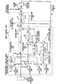
- FIG.1 is a block diagram of a conventional two degrees of freedom type PID control system wherein P operation and D operation are given two degrees of freedom.
- a target value filter 11 that carries out calculation processing that obtains the proportional gain and derivative time in two degrees of freedom type.
- the system receives a target value SV from a target value generating unit 10 and feeds to a deviation calculation unit 13 a control amount PV from a system 12 to be controlled and filter output SVo obtained from target value filter 11.
- Deviation calculation unit 13 performs the calculation (SVo - PV) to find the deviation E, which is then fed to a PI control calculation unit 14.
- This PI control calculation unit 14 receives deviation E and performs PI control calculation to obtain an operating signal MV, which is then fed to an adding unit 15.
- coefficient unit 21 multiplies target value SV by proportional gain revision coefficient ⁇ for realizing two degrees of freedom for proportional control operation, to obtain a output (SV. ⁇ ), which is then fed to an adding unit 22.
- a subtraction unit 23 then subtracts the output (SV. ⁇ ) of coefficient unit 21 from target value SV.
- the subtraction output SV(1 - ⁇ ) which is obtained is then supplied to a subtraction unit 24.
- the output (SV. ⁇ ) of the coefficient unit 21 is also fed to a coefficient unit 25 which multiplies this output (SV. ⁇ ) by derivative time revision coefficient ⁇ for realizing two degrees of freedom of derivative control operation to obtain a multiplied output (SV. ⁇ . ⁇ ), which is then fed to a subtraction unit 26.
- This subtraction unit 26 subtracts control amount PV from multiplied output (SV. ⁇ . ⁇ ), to obtain a subtracted output (SV. ⁇ . ⁇ ) - PV, which is fed to a coefficient unit 27, where this subtraction output (SV. ⁇ . ⁇ ) - PV is multiplied by derivative gain 1/ ⁇ .
- the output of this coefficient unit 27 is branched into two. One of these outputs is input directly to a subtraction unit 28. The other outputs is input to subtraction means 28 through a first order delay element 29.
- subtraction unit 28 the output of first order delay element 29 is subtracted from the output of coefficient means 27, and the result is then supplied to subtraction unit 24.
- This subtraction unit 24 then subtracts the output of subtraction unit 28 from the output of subtraction unit 23.
- the output obtained is given an appropriate delay by passing it through a first order delay element 30 whose time constant is the integral time T I .
- An adding unit 31 then adds the output of this first order delay element 30 and the output of subtraction unit 28.
- Adding unit 22 then adds this to the output of a coefficient unit 21, to obtain the output SVo of target value filter 11.
- the values of the coefficient ⁇ used to give the proportional gain revision coefficient for relaizing two degrees of freedom differ greatly, depending on which of the above combinations is selected. Consequently, in a plant employing several hundred to several thousand PID control loops, it is necessary to change the setting of the value of coefficient ⁇ every time. This takes a considerable amount of time, It is also possible that the value of the coefficient ⁇ that is to be set might be forgotten.
- Another object is to make it possible to automatically set a desirable value of proportional gain revision coefficient realizing two degrees of freedom for proportional control operation in a process control system.
- the foregoing objects are achieved according to the present invention by providing a system for controlling a process system subject to an external disturbance by adjusting the value of a control amount output from the process system to a given target value.
- the system includes target value generating means for generating a given target value, and main control means receiving the target value and the control amount value for performing control operations to surpress fluctuation of the control amount value produced by the external disturbance and to adjust the control amount value to the given target value.
- the main control means includes surpessing means for performing at least proportional and integral control operations from a choice of proportional, integral and derivative control operations based on control constants including at least proportional gain, integral time from a choice of proportional gain, integral time and derivative time adjusted to suppress fluctuations of the control amount value produced by the external disturbance, adjusting means for performing at least proportional and integral control operations from a choice of proportional, integral and derivative control operations according to at least a given proportional gain revision coefficient to adjust a proportional gain of the surpressing means from a choice of the given proportional gain revision coefficient adjusted and a given derivative time revision coefficient to adjust a derivative time of the surpressing means, to adjust the control amount value to the given target value, proportional gain revision coefficient means for setting a plurality of given gain revision coefficients, and coefficient selecting means for selecting the given gain revision coefficient from among the plurality of given gain revision coefficients according to the result of descriminating whether a derivative control operation of the surpressing means is performed and whether a derivative control operation of the adjusting means is performed.
- FIG. 1 is a block diagram of a conventional two degrees of freedom type PID control system.
- FIG. 2 is a block diagram of an embodiment of two degrees of freedom type PID control system according to the invention.
- FIG. 3 is a block diagram of another embodiment of the invention.
- FIG. 4 is a block diagram of a further embodiment of the invention.
- K is the gain of the control system
- T is the time constant
- L is the dead time
- proportional gain revision coefficient ⁇ for realizing two degrees of freedom for porportional control operation can be obtained, as shown in Table 2, depending on the combination of whether or not there is a derivative control action on the target value SV and whether or not there is a derivative control operation on the control amount (which is influenced by external disturbance).
- the value of the proportional gain revision coefficient ⁇ differs greatly, from 0.37 to 0.63, depending on the control mode i.e. on the combination of whether or not a derivative control action is performed on the target value SV and whether or not a derivative control action is performed on the control amount (which is influenced by disturbance).
- FIG. 2 a main control unit 16 having the function of discriminating the combination of derivative time T D and derivative time revision coefficient ⁇ for two degrees of freedom of derivative control operation, is utilized. Items in FIG. 2 which are the same as items in FIG. 1 are given the same reference numerals and a detailed description is omitted.
- this device is constructed by providing, within target value filter 11, proportional gain revision coefficient setting units 17, 18 that set two (or, in other cases,) coefficients ⁇ 1, ⁇ 2, of proportional gain in accordance for example with Table 2. Also provided is a discriminating unit 19 that discriminates the combination of derivative time T D and the coefficient ⁇ of derivative time by inputting the value of the derivative time T D that is set by a first order delay element 29, and the coefficient ⁇ of derivative time that is set by a coefficient unit 25.
- a selecting unit 20 that automatically selects the optimum value from among the proportional gain revision coefficients that are set beforehand by proportional gain revision coefficient setting units 17 and 18 in accordance with the result of descrimination by descriminating unit 19, i.e., in accordance with changes of the combination of derivative time T D and derivative time revision coefficient ⁇ .
- the coefficient ⁇ of proportional gain selected by this selecting unit 20 is set in coefficient unit 21.
- Descriminating unit 19 inputs the value of the derivative time T D that is set by first order delay element 29 and the coefficient ⁇ of derivative time that is set by coefficient unit 25. In accordance with this coefficient ⁇ and derivative time T D , it then sets in coefficient unit 21 the following:
- the very different values of the coefficient ⁇ depending on the combination of whether or not there is a derivative control action on the target value SV and whether or not there is a derivative control action on the control amount (which is influenced by external disturbance) are identified.
- the optimum proportional gain revision coefficients are set beforehand in proportional gain revision coefficient setting units 17 and 18, and descriminating unit 19 fetches one of the optimum proportional gain revision coefficients from proportional gain revision coefficient setting units 17 or 18 after discriminating derivative time T D and the coefficient ⁇ of derivative time and sets this optimum proportional gain revision coefficient automatically in coefficient unit 21.
- FIG. 3 Another embodiment of the invention is shown in FIG. 3.
- a first order delay element 32 is inserted between subtraction unit 23 and subtraction unit 24 of target value filter 11.
- Complete two degrees of freedom PID control is obtained by obtaining the integral time T I equivalently in two degrees of freedom form, by applying a coefficient ⁇ to the time constant of this first order delay element 32, i.e. by using a time constant ⁇ T I .
- the optimum value of the coefficient ⁇ of proportional gain can of course be set in coefficient unit 21 in accordance with the combination of derivative time T D and the coefficient ⁇ of derivative time, in the same way as in FIG. 2, with this target value filter 11 also.
- FIG. 4 showns yet a further embodiment of the invention.
- a first order delay element 33 is provided on the output side of subtraction unit 23 of target value filter 11, and a subtraction 34 that subtracts the output of this first order delay element 32 from the output of subtraction unit 28 is provided.
- Full two degrees of freedom PID control is obtained by equivalently obtaining the integral time T D in two degrees of freedom form, by using the coefficient of ⁇ with this first order delay element 33.
- the optimum value of the coefficient ⁇ of proportional gain can be set in coefficient unit 21, depending on the combination of derivative time T D and the coefficient ⁇ of derivative time, in this case too.
- the optimum coefficient of proportional gain can be automatically selected and set in accordance with the combination of derivative time T D and the coefficient ⁇ of derivative time.
- a two degrees of freedom control device can thus be provided that is easy to adjust, and that offers high controllability and versatility.
Landscapes
- Engineering & Computer Science (AREA)
- Physics & Mathematics (AREA)
- General Physics & Mathematics (AREA)
- Automation & Control Theory (AREA)
- Human Computer Interaction (AREA)
- Manufacturing & Machinery (AREA)
- Feedback Control In General (AREA)
Applications Claiming Priority (2)
| Application Number | Priority Date | Filing Date | Title |
|---|---|---|---|
| JP58438/90 | 1990-03-09 | ||
| JP2058438A JP2839626B2 (ja) | 1990-03-09 | 1990-03-09 | 2自由度調節装置 |
Publications (2)
| Publication Number | Publication Date |
|---|---|
| EP0445940A1 true EP0445940A1 (de) | 1991-09-11 |
| EP0445940B1 EP0445940B1 (de) | 1995-04-26 |
Family
ID=13084405
Family Applications (1)
| Application Number | Title | Priority Date | Filing Date |
|---|---|---|---|
| EP91301454A Expired - Lifetime EP0445940B1 (de) | 1990-03-09 | 1991-02-22 | Prozessregelungsvorrichtung |
Country Status (5)
| Country | Link |
|---|---|
| EP (1) | EP0445940B1 (de) |
| JP (1) | JP2839626B2 (de) |
| KR (1) | KR950003551B1 (de) |
| CN (1) | CN1026922C (de) |
| DE (1) | DE69109159T2 (de) |
Cited By (6)
| Publication number | Priority date | Publication date | Assignee | Title |
|---|---|---|---|---|
| EP0417635B1 (de) * | 1989-09-11 | 1996-04-03 | Kabushiki Kaisha Toshiba | Regler mit zwei Freiheitsgraden |
| WO1997011414A1 (en) * | 1995-09-22 | 1997-03-27 | Rosemount Inc. | Adaptive bias controller |
| US8150784B2 (en) | 2005-08-12 | 2012-04-03 | Sumco Techxiv Corporation | Control system and method for controlled object in time variant system with dead time, such as single crystal production device by czochralski method |
| EP2724918A3 (de) * | 2012-10-24 | 2016-03-23 | Jtekt Corporation | POD-Steuerungssystem |
| EP3349074A1 (de) * | 2017-01-13 | 2018-07-18 | Omron Corporation | Steuerungsvorrichtung, steuerungsverfahren und steuerungsprogramm zur abstimmung einer bedienungsgrösse eines geräts |
| CN119770299A (zh) * | 2025-03-07 | 2025-04-08 | 广东施泰宝医疗科技有限公司 | 一种骨科关节置换手术台及控制方法 |
Families Citing this family (2)
| Publication number | Priority date | Publication date | Assignee | Title |
|---|---|---|---|---|
| JP4955237B2 (ja) * | 2005-08-12 | 2012-06-20 | Sumco Techxiv株式会社 | 無駄時間をもつ時変系制御対象のための制御システム及び方法 |
| JP5763598B2 (ja) * | 2012-07-31 | 2015-08-12 | 株式会社日立製作所 | プラント制御装置、プラント制御方法及びプラント制御プログラム |
Citations (1)
| Publication number | Priority date | Publication date | Assignee | Title |
|---|---|---|---|---|
| EP0333477A2 (de) * | 1988-03-18 | 1989-09-20 | Kabushiki Kaisha Toshiba | Prozessregelungssystem |
Family Cites Families (1)
| Publication number | Priority date | Publication date | Assignee | Title |
|---|---|---|---|---|
| JPS61196302A (ja) * | 1985-02-27 | 1986-08-30 | Toshiba Corp | 調節装置 |
-
1990
- 1990-03-09 JP JP2058438A patent/JP2839626B2/ja not_active Expired - Lifetime
-
1991
- 1991-02-22 DE DE69109159T patent/DE69109159T2/de not_active Expired - Fee Related
- 1991-02-22 EP EP91301454A patent/EP0445940B1/de not_active Expired - Lifetime
- 1991-03-09 KR KR1019910003805A patent/KR950003551B1/ko not_active Expired - Fee Related
- 1991-03-09 CN CN91101529A patent/CN1026922C/zh not_active Expired - Fee Related
Patent Citations (1)
| Publication number | Priority date | Publication date | Assignee | Title |
|---|---|---|---|---|
| EP0333477A2 (de) * | 1988-03-18 | 1989-09-20 | Kabushiki Kaisha Toshiba | Prozessregelungssystem |
Non-Patent Citations (2)
| Title |
|---|
| PATENT ABSTRACTS OF JAPAN vol. 12, no. 259 (P-733)(3106) 21 July 1988, & JP-A-63 46502 (YOKOGAWA ELECTRIC CORP) 27 February 1988, * |
| PATENT ABSTRACTS OF JAPAN vol. 12, no. 259 (P-733)(3106) 21 July 1988, & JP-A-63 46503 (YOKOGAWA ELECTRIC CORP) 27 February 1988, * |
Cited By (7)
| Publication number | Priority date | Publication date | Assignee | Title |
|---|---|---|---|---|
| EP0417635B1 (de) * | 1989-09-11 | 1996-04-03 | Kabushiki Kaisha Toshiba | Regler mit zwei Freiheitsgraden |
| WO1997011414A1 (en) * | 1995-09-22 | 1997-03-27 | Rosemount Inc. | Adaptive bias controller |
| US5812428A (en) * | 1995-09-22 | 1998-09-22 | Rosemount Inc. | Process controller having non-integrating control function and adaptive bias |
| US8150784B2 (en) | 2005-08-12 | 2012-04-03 | Sumco Techxiv Corporation | Control system and method for controlled object in time variant system with dead time, such as single crystal production device by czochralski method |
| EP2724918A3 (de) * | 2012-10-24 | 2016-03-23 | Jtekt Corporation | POD-Steuerungssystem |
| EP3349074A1 (de) * | 2017-01-13 | 2018-07-18 | Omron Corporation | Steuerungsvorrichtung, steuerungsverfahren und steuerungsprogramm zur abstimmung einer bedienungsgrösse eines geräts |
| CN119770299A (zh) * | 2025-03-07 | 2025-04-08 | 广东施泰宝医疗科技有限公司 | 一种骨科关节置换手术台及控制方法 |
Also Published As
| Publication number | Publication date |
|---|---|
| DE69109159T2 (de) | 1995-08-31 |
| EP0445940B1 (de) | 1995-04-26 |
| CN1054676A (zh) | 1991-09-18 |
| JP2839626B2 (ja) | 1998-12-16 |
| JPH03259301A (ja) | 1991-11-19 |
| KR910017257A (ko) | 1991-11-05 |
| AU7269491A (en) | 1991-09-12 |
| AU621254B2 (en) | 1992-03-05 |
| KR950003551B1 (ko) | 1995-04-14 |
| DE69109159D1 (de) | 1995-06-01 |
| CN1026922C (zh) | 1994-12-07 |
Similar Documents
| Publication | Publication Date | Title |
|---|---|---|
| DE3889014T2 (de) | Prozesssteuerung mit einer Kombination von direkter und rückgekoppelter Steuerung. | |
| EP0333477B1 (de) | Prozessregelungssystem | |
| JPH0298701A (ja) | 制御装置 | |
| EP0445940B1 (de) | Prozessregelungsvorrichtung | |
| AU648213B1 (en) | Process control apparatus | |
| US5200681A (en) | Process control system | |
| KR940003149B1 (ko) | 2자유도 제어기 | |
| US4953076A (en) | Versatile time difference comparison compensation method of control system | |
| US5245529A (en) | Two degrees of freedom type control system | |
| JPS6121505A (ja) | プロセス制御装置 | |
| JP3034404B2 (ja) | 2自由度pid調節装置 | |
| JPH0556522B2 (de) | ||
| JP2772059B2 (ja) | 2自由度pid制御装置 | |
| JPS6346503A (ja) | Pid調節装置 | |
| JP2766395B2 (ja) | 制御装置 | |
| JPS61190602A (ja) | 調節装置 | |
| JP3004152B2 (ja) | 2自由度pid調節装置 | |
| JP2845534B2 (ja) | 2自由度調節装置 | |
| JPH07311601A (ja) | 2自由度pid調節装置 | |
| JP2809849B2 (ja) | 2自由度調節装置 | |
| JP3015553B2 (ja) | 補完フィードバック制御装置 | |
| JP3124169B2 (ja) | 2自由度調節装置 | |
| JPS59128603A (ja) | プロセス制御装置 | |
| JP2557819B2 (ja) | Bwr発電プラントのサンプル値pid制御装置 | |
| SU1303994A1 (ru) | Нелинейный адаптивный регул тор |
Legal Events
| Date | Code | Title | Description |
|---|---|---|---|
| PUAI | Public reference made under article 153(3) epc to a published international application that has entered the european phase |
Free format text: ORIGINAL CODE: 0009012 |
|
| 17P | Request for examination filed |
Effective date: 19910308 |
|
| AK | Designated contracting states |
Kind code of ref document: A1 Designated state(s): DE FR GB |
|
| 17Q | First examination report despatched |
Effective date: 19930709 |
|
| GRAA | (expected) grant |
Free format text: ORIGINAL CODE: 0009210 |
|
| AK | Designated contracting states |
Kind code of ref document: B1 Designated state(s): DE FR GB |
|
| REF | Corresponds to: |
Ref document number: 69109159 Country of ref document: DE Date of ref document: 19950601 |
|
| ET | Fr: translation filed | ||
| PLBE | No opposition filed within time limit |
Free format text: ORIGINAL CODE: 0009261 |
|
| STAA | Information on the status of an ep patent application or granted ep patent |
Free format text: STATUS: NO OPPOSITION FILED WITHIN TIME LIMIT |
|
| 26N | No opposition filed | ||
| PGFP | Annual fee paid to national office [announced via postgrant information from national office to epo] |
Ref country code: FR Payment date: 19970211 Year of fee payment: 7 |
|
| PGFP | Annual fee paid to national office [announced via postgrant information from national office to epo] |
Ref country code: GB Payment date: 19970213 Year of fee payment: 7 |
|
| PGFP | Annual fee paid to national office [announced via postgrant information from national office to epo] |
Ref country code: DE Payment date: 19970228 Year of fee payment: 7 |
|
| PG25 | Lapsed in a contracting state [announced via postgrant information from national office to epo] |
Ref country code: GB Free format text: LAPSE BECAUSE OF NON-PAYMENT OF DUE FEES Effective date: 19980222 |
|
| PG25 | Lapsed in a contracting state [announced via postgrant information from national office to epo] |
Ref country code: FR Free format text: THE PATENT HAS BEEN ANNULLED BY A DECISION OF A NATIONAL AUTHORITY Effective date: 19980228 |
|
| GBPC | Gb: european patent ceased through non-payment of renewal fee |
Effective date: 19980222 |
|
| PG25 | Lapsed in a contracting state [announced via postgrant information from national office to epo] |
Ref country code: DE Free format text: LAPSE BECAUSE OF NON-PAYMENT OF DUE FEES Effective date: 19981103 |
|
| REG | Reference to a national code |
Ref country code: FR Ref legal event code: ST |